AMX MST-1001 Configuration Manual
Modero s series tabletop touch panel and landscape wall mount touch panel
Hide thumbs
Also See for MST-1001:
- Quick start manual (2 pages) ,
- Instruction manual (48 pages) ,
- Installation & hardware reference manual (38 pages)
Table of Contents
Advertisement
CO N F IG U RATI O N & P RO G RA M M IN G M A NU A L
M O DE RO S S E R I ES TO U C H PA N E L S
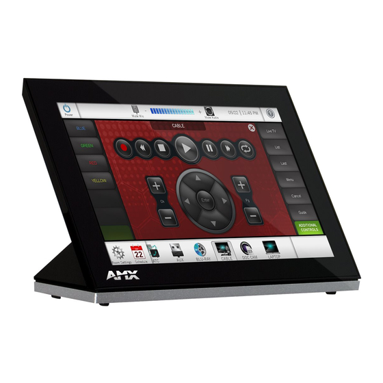
MST-1001 10.1" MODERO S SERIES TABLETOP TOUCH PANEL
MSD-1001-L 10 .1 " MODER O S SERI ES LAN DSCAPE WALL MOUN T TOUCH PANEL
MST-701 7" MODER O S SERI ES TABLETOP TOUCH PAN EL
MSD-701-L 7" MODERO S SERIES LANDSCAPE WALL MOUNT TOUCH PANEL
MST-431 4. 3" MODERO S SERI ES TABLETOP TOUCH P AN EL
MSD-431-L 4.3" MODERO S SERIES LANDSCAPE WALL MOUNT TOUCH PANEL
Advertisement
Table of Contents

Related Manuals for AMX MST-1001


Summary of Contents for AMX MST-1001
- Page 1 M O DE RO S S E R I ES TO U C H PA N E L S MST-1001 10.1" MODERO S SERIES TABLETOP TOUCH PANEL MSD-1001-L 10 .1 " MODER O S SERI ES LAN DSCAPE WALL MOUN T TOUCH PANEL MST-701 7"...
-
Page 2: Copyright Notice
COPYRIGHT NOTICE AMX© 2015, all rights reserved. No part of this publication may be reproduced, stored in a retrieval system, or transmitted, in any form or by any means, electronic, mechanical, photocopying, recording, or otherwise, without the prior written permission of AMX. Copyright protection claimed... -
Page 3: Table Of Contents
Table of Contents Table of Contents Modero S Series ® Programming ..............9 Overview ..........................9 Settings Pages ....................10 Overview ......................... 10 Accessing the Settings Page ..................10 Using the Settings Pages ....................10 Saving Changed Settings........................11 Settings .......................... 11 Status .......................... - Page 4 Table of Contents Admin Configuration..........................29 Admin Passwords ..........................30 Security..............................30 Install Firmware............................ 31 Resetting to Factory-Installed Firmware ..................... 31 Installing Previous Firmware........................ 32 Installing New Firmware From An External USB Stick ................. 33 SIP................................. 34 Changing the SIP Proxy Address......................35 Changing the SIP Port Number ......................
- Page 5 Table of Contents Page Commands ......................45 @APG..................................... 45 @CPG..................................... 45 @DPG ..................................... 45 @PDR ..................................... 45 @PHE ..................................... 45 WAKE ..................................... 45 @PHP ..................................... 46 @PHT ..................................... 46 @PPA ..................................... 46 @PPF...................................... 46 @PPG ..................................... 46 @PPK ..................................... 47 @PPM.....................................
- Page 6 Table of Contents ^CPF ...................................... 60 ^DPF....................................... 60 ^DVS ...................................... 61 ^ENA ...................................... 61 ^FON ...................................... 61 ?FON....................................... 61 ^GDI....................................... 61 ^GIV......................................62 ^GLH ....................................... 62 ^GLL......................................62 ^GRD ....................................... 62 ^GRU....................................... 62 ^GSC ....................................... 62 ^GSN ....................................... 63 ^ICO......................................63 ?ICO ......................................
- Page 7 Table of Contents Intercom Commands i....................74 ^MODEL?....................................74 ^ICS-...................................... 74 ^ICE' ...................................... 74 ^ICM-LISTEN ..................................74 ^ICM-MICLEVEL..................................74 ^ICM-MUTEMIC..................................74 ^ICM-SPEAKERLEVEL ................................75 ^ICM-TALK .................................... 75 ^IIC......................................75 ^IOC....................................... 75 SIP Commands ....................... 76 Panel to Master ............................. 76 ^PHN-AUTOANSWER ................................
- Page 8 ^SHD ....................................... 86 ^SSH ....................................... 86 ^STG ....................................... 86 Custom Events........................ 87 Bluetooth Headsets ..........................87 AMX Bluetooth Handset Custom Event ..........................87 Dynamic Images ........................... 87 Resource Load Notification custom event..........................87 Popups ..............................87 ^PUN...................................... 87 Smart Cards ............................88 Smart Card Insert/Remove ..............................
-
Page 9: Modero S Series ® Programming
Modero S Series experience, please refer to the TPDesign4 Operation Reference Guide and the User Interface Design Guide, both available at www.amx.com. The Modero S-Series touch panels covered in this document are listed in the following table:... -
Page 10: Settings Pages
Settings Pages Settings Pages Overview Modero S Series touch panels do not have separate Setup and Protected Setup pages. All touch panel settings and functionality are now controlled through one Settings page. The Connection & Networks and Conf iguration sections are accessible with the correct password. -
Page 11: Saving Changed Settings
Settings Pages Drag the slidebar to adjust the panel brightness. Press the button to enable or disable the feature. Use the Up/Down arrows to adjust the information listed between them. Press the arrow to move to the next page (in this case, the Calibration page). -
Page 12: Status
Settings Pages Settings Page (Cont.) Display: Select this to go to the Display page (page 14) Sounds: Select this to go to the Sounds page (page 15). Date & Time: Select this to go to the Date & Time page (page 16). Connection &... -
Page 13: File Information
Settings Pages File Information The File Information page (FIG. 7) displays information on the TPDesign4 project file currently loaded on the panel. File Information page FIG. 7 File Information Page Back: Click the left-facing arrow to return to the previous page. Connection Status: A green bar signifies that the panel has an active connection to the Master. -
Page 14: Display
Settings Pages Display The Display page (FIG. 8) controls the basic functions of the touch panel display, including the panel brightness. Display page FIG. 8 Display Page Back: Click the left-facing arrow to return to the previous page. Connection Status: A green bar signifies that the panel has an active connection to the Master. Close: Click the “X”... -
Page 15: Sounds
Settings Pages NOTE: If the screen is not touched at that point, the device will automatically return to the Calibration page within 10 seconds. In certain circumstances, you may wish to test the calibration of a panel without actually recalibrating it. The Calibration Test page (FIG. -
Page 16: Creating A Custom Sound Set
Settings Pages Sounds Page Play Test: Press this button to test the audio output by playing a preselected sound. Button Hit: Press this button to enable the panel to play a default sound whenever a button on a page is selected. Button Hit Sound: Displays the information on the sound file associated with the Button Hit function. -
Page 17: Connection & Networks
Settings Pages Date & Time Page Back: Click the left-facing arrow to return to the previous page. Connection Status: A green bar signifies that the panel has an active connection to the Master. Close: Click the “X” button to shut the Settings page and return to the main display. Year: Use the Up/Down arrows to set the current year. -
Page 18: Master Connection
Settings Pages Master Connection The Master Connection page (FIG. 16) controls the method of connection to a NetLinx Master. Master Connection page FIG. 16 Master Connection Page Back: Click the left-facing arrow to return to the previous page. Connection Status: A green bar signifies that the panel has an active connection to the Master. -
Page 19: Changing The Master Connection Mode
Settings Pages Changing the Master Connection Mode To change the Master Connection mode between URL, Listen, and Auto: From the Master Connection page, press the Mode field to change the mode. Keep pressing to bring up the desired mode. When finished, press Back to return to the Settings page. Changing the Master IP/URL To change the IP address or URL for the chosen Master: From the Master Connection page, press the Master IP/URL field to open the Master IP Address keyboard (FIG. -
Page 20: Network Connection
Settings Pages To change the password: From the Master Connection page, press the Password field to open the Master Password keyboard (FIG. 21). Master Password keyboard FIG. 21 Enter the new password in the keyboard field and press OK. When finished, press Back to return to the Settings page. Network Connection The Network Connection page (FIG. -
Page 21: Setting Static Ip Information
Settings Pages Setting Static IP Information When using DHCP settings for a panel, the DHCP server will automatically populate almost all of the Network Connections page fields, with the exception of Hostname. When setting the panel for Static, however, this information must be entered manually. To enter the network connection information: In DHCP/Static, press the field until the entry reads “Static”. -
Page 22: Bluetooth Device Search
Settings Pages Bluetooth Page (Cont,) Connected: Displays if the device is currently connected to the touch panel. Disconnect: After choosing a Bluetooth paired device, select this button to disconnect the paired device but keep it in the list. Remove: After choosing a Bluetooth paired device, select this button to remove the device from the list. Up/Down: Use the Up/Down arrows to select the Bluetooth device currently connected to the touch panel. - Page 23 Settings Pages When the panel is finished scanning for Bluetooth devices, those devices still need to be paired with the touch panel if they have not done so before. In the search list, select the device to be paired and click Connect (FIG. 28). Selecting a Bluetooth device FIG.
-
Page 24: Smart Card
Smart Card Use of this feature requires the use of an AMX-approved CAC reader, as shown below. The Smart Card page (FIG. 33) controls the touch panel’s ability to receive and process information from Common Access Card (CAC) smart card readers. -
Page 25: Breakout Box
If a Breakout Box is not connected to the panel’s network, all fields but the Breakout Box button will be empty. NOTE: For more information on operation and conf iguration of an MXA-MP or MXA-MPL, please refer to the MXA-MP/MPL Operation Reference Guide, available at www.amx.com. Breakout Box page FIG. 34... -
Page 26: Panel Configuration
Settings Pages Conf iguration Page Back: Click the left-facing arrow to return to the previous page. Connection Status: A green bar signifies that the panel has an active connection to the Master. Close: Click the “X” button to shut the Settings page and return to the main display. Panel: Select this to open the Panel Conf iguration page (page 26). -
Page 27: Changing The Device Name
Settings Pages Device Number keypad FIG. 37 Enter the new device number and press OK. The Device Number field in the Panel Conf iguration page will now display the new device number. Changing the Device Name To change the name associated with the touch panel: From the Panel Conf iguration page, select the Device Name field to open the Device Name keyboard (FIG. -
Page 28: G4 Webcontrol
Settings Pages G4 WebControl An on-board VNC (Virtual Network Computing) server allows any remote PC running a VNC client to connect to the panel. Once connected, the client can view and control the panel remotely. The options on the G4 WebControl page (FIG. 40) allow you to enable or disable G4 WebControl functionality. -
Page 29: Synchronizing Device Names
Settings Pages Synchronizing Device Names For ease of connectivity, it may be desirable or necessary to make sure that all of the names registered with the panel are the same. Enabling the Synchronize Device Names button synchronizes these names, tracking any changes to the current Device Name setting. -
Page 30: Admin Passwords
Settings Pages Admin Passwords The options on the Admin Passwords page allow assignment of passwords required for users to access the secured Settings pages. Admin Passwords page FIG. 44 Passwords Page Back: Click the left-facing arrow to return to the previous page. Connection Status: A green bar signifies that the panel has an active connection to the Master. -
Page 31: Install Firmware
• Minimum password requirement is 8 characters with at least one numeric character. • Remote login uses SSH. • Remote login user name is amx. • Login failure attempt pauses 4 seconds before another login attempt is allowed. • After 3 consecutive unsuccessful SSH login attempts, login lockout is enabled for 15 minutes. -
Page 32: Installing Previous Firmware
Settings Pages Install Factory Firmware system message FIG. 48 Within five seconds, the Yes button will be enabled. At that time, select Yes to install the factory firmware and No to return to the Install Firmware page. If you choose Yes, the touch panel will reboot and restart with the factory default firmware. To reset the touch panel to its original factory firmware from the panel bootup: Immediately after the touch panel boots up, the device’s splash page appears on the screen (FIG. -
Page 33: Installing New Firmware From An External Usb Stick
To install new firmware to the touch panel from an external disk via the Settings pages: Download the latest Modero S Series touch panel firmware from www.amx.com and save it to a USB stick. NOTE: The f irmware must be saved in a folder in the USB stick directory, corresponding with the touch panel model, in order to be recognized by the touch panel. -
Page 34: Sip
Settings Pages Firmware Not Initiated screen FIG. 53 Upgrade In Progress screen FIG. 54 Once the upgrade is complete, the touch panel will automatically reboot with the new firmware. You may remove the USB stick from the USB A port once the dots in the splash page (FIG. 49) start moving. If you do not remove the USB stick, the update initiation screen will appear again. -
Page 35: Changing The Sip Proxy Address
Settings Pages SIP Page (Cont.) SIP: This option enables the SIP Stack on startup. If you disable this option, the panel will not attempt to read the rest of the configuration and will not register with a proxy server. However, point-to-point SIP will still be enabled allowing for existing intercom functionality. -
Page 36: Advanced Config
Settings Pages SIP STUN Address Keyboard FIG. 58 Enter the STUN server address and click OK. Click Save to save your changes to the SIP page and return to the Conf iguration page. Advanced Conf ig The Advanced Conf ig page (FIG. 59) displays options for more advanced configuration options, such as running diagnostics or modifying the options for streaming video. -
Page 37: Diagnostics
Settings Pages The size of RAM cache is automatically configured to take into account available memory versus memory that may be needed by the panel later. As the RAM cache approaches its maximum size, the oldest items in the cache may be discarded to make room for newer items. -
Page 38: Logs
Settings Pages Logs The Logs page (FIG. 62) chronicles all previous connections between the device and the network. Logs page FIG. 62 Logs Page Back: Click the left-facing arrow to return to the previous page. Connection Status: A green bar signifies that the panel has an active connection to the Master. Close: Click the “X”... -
Page 39: Connection Utility
The Streaming Video page (FIG. 66) is used to preview video sources, such as those coming through an MXA-MP or MXA-MPL. For more information on these devices, please refer to the MXA-MP/MPL Operation Reference Guide, available at www.amx.com. Streaming Video page FIG. -
Page 40: Entering A Streaming Video Url
Settings Pages Streaming Video Page Back: Click the left-facing arrow to return to the previous page. Connection Status: A green bar signifies that the panel has an active connection to the Master. Close: Click the “X” button to shut the Settings page and return to the main display. Enter URL: Select this to enter the URL for the video stream to be displayed. -
Page 41: Programming
Programming Programming Overview You can program Modero S Series touch panels, using the commands in this section, to perform a wide variety of operations using Send Commands and variable text commands. These commands are used in NetLinx Programming Language and are case insensitive. -
Page 42: Akp
Programming Panel Commands (Cont.) @AKP Pop up the keypad icon and initialize the text string to that specified. Keypad string is set to null on power up and is stored until power is lost. The Prompt Text is optional. • Syntax: "'@AKP-<initial text>;<prompt text>'"... -
Page 43: Kps
Programming Panel Commands (Cont.) ^KPS Set the keyboard passthru. • Syntax: "'^KPS-<pass data>'" • Variables: pass data: <blank/empty> = Disables the keyboard. 0 = Pass data to G4 application (default). This can be used with VPC or text areas. 1 - 4 = Not used. 5 = Sends out data to the Master. -
Page 44: Shutdown
Programming Panel Commands (Cont.) SHUTDOWN Shut down the batteries providing power to the panel. • Syntax: "'SHUTDOWN'" • Example: SEND COMMAND Panel,"'SHUTDOWN'" Shuts-down the batteries feeding power to the panel. This function saves the battery from discharging. SLEEP Force the panel into screen saver mode. •... -
Page 45: Page Commands
Programming Panel Commands (Cont.) WAKE Force the panel out of screen saver mode. • Syntax: "'WAKE'" • Example: SEND COMMAND Panel,"'WAKE'" Forces the panel out of the screen saver mode. Page Commands Page Commands @APG Add a specific popup page to a specified popup group if it does not already exist. If the new popup is added to a group which has a popup displayed on the current page along with the new pop-up, the displayed popup will be hidden and the new popup will be displayed. -
Page 46: Php
Programming Page Commands (Cont.) @PHP Set the hide effect position - Only 1 coordinate is ever needed for an effect; however, the command will specify both. This command sets the location at which the effect will end at. • Syntax: "'@PHP-<popup page name>;<x coordinate>,<y coordinate>'"... -
Page 47: Ppk
Programming Page Commands (Cont.) @PPK Kill a specific popup page from all pages. Kill refers to the deactivating (Off) of a popup window from all pages. If the pop-up page is part of a group, the whole group is deactivated. This command works in the same way as the 'Clear Group' command in TPDesign 4. -
Page 48: Psp
Programming Page Commands (Cont.) @PSP Set the show effect position. Only 1 coordinate is ever needed for an effect; however, the command will specify both. This command sets the location at which the effect will begin. • Syntax: "'@PSP-<popup page name>;<x coordinate>,<y coordinate>'" •... -
Page 49: Button Commands
Programming Page Commands (Cont.) PPON Activate a specific popup page to launch on either a specified page or the current page.If the page name is empty, the current page is used (see example 2). If the popup page is already On, do not re-draw it. This command works in the same way as the ’Show Popup’... -
Page 50: Ani
Programming Button Commands ^ANI Run a button animation (in 1/10 second). • Syntax: "'^ANI-<vt addr range>,<start state>,<end state>,<time>'" • Variables: variable text address range = 1 - 4000. start state = Beginning of button state (0= current state). end state = End of button state. time = In 1/10 second intervals. -
Page 51: Bcb
Programming Button Commands (Cont.) ?BCB Get the current border color. • Syntax: "'?BCB-<vt addr range>,<button states range>'" • Variables: variable text address range = 1 - 4000. button states range = 1 - 256 for multi-state buttons (0 = All states, for General buttons 1 = Off state and 2 = On state). custom event type 1011: Flag - zero Value1 - Button state number... -
Page 52: Bct
Programming Button Commands (Cont.) ^BCT Set the text color to the specified color. This applies only if the specified text color is not the same as the current color. Note: Color can be assigned by color name (without spaces), number or R,G,B value (RRGGBB or RRGGBBAA). •... -
Page 53: Bim
Programming Button Commands (Cont.) ^BIM Set the input mask for the specified address. • Syntax: "'^BIM-<vt addr range>,<input mask>'" • Variables: variable text address range = 1 - 4000. input mask = Refer to the Text Area Input Masking table on page 110 for character types. •... -
Page 54: Bmf
Programming Button Commands (Cont.) ^BMF Set any/all button parameters by sending embedded codes and data. • Syntax: "'^BMF-<vt addr range>,<button states range>,<data>'" Note: Many subcommands do not use button state information. Refer to the subcommand for details. • Variables: variable text address char array = 1 - 4000. button states range = 1 - 256 for multi-state buttons (0 = All states, for General buttons 1 = Off state and 2 = On state). -
Page 55: Bmi
Programming Button Commands (Cont.) ^BMF ’%OT<feedback type>’ = Set the Feedback (Output) Type to one of the following: None, Channel,Invert, ON (Always (Cont.) ON), Momentary, or Blink. Note: This parameter should be always used in its own BMF command, and should not be combined with other BMF subcommands. -
Page 56: Bmp
Programming Button Commands (Cont.) ?BMP Get the current bitmap name. • Syntax: "'?BMP-<vt addr range>,<button states range>'" • Variables: variable text address range = 1 - 4000. button states range = 1 - 256 for multi-state buttons (0 = All states, for General buttons 1 = Off state and 2 = On state). custom event type 1002: Flag - Zero Value1 - Button state number... -
Page 57: Bop
Set a border to a specific border style associated with a border value for those buttons with a defined address range.Sets the border by name (AMX Elite) to those buttons with the variable text range of 500-504 & 510-515. The border style is available through the TPDesign4 border-style drop-down list. -
Page 58: Bpp
Programming Button Commands (Cont.) ^BPP Set or clear the protected page flip flag of a button. Sets the button to protected page flip flag 1 (sets it to password 1). • Syntax: "'^BPP-<vt addr range>,<protected page flip flag value>'" • Variables: variable text address range = 1 - 4000. -
Page 59: Bso
Programming Button Commands (Cont.) ^BSO Set the sound played when a button is pressed. If the sound name is blank, the sound is then cleared. If the sound name is not matched, the button sound is not changed. • Syntax: "'^BSO-<vt addr range>,<button states range>,<sound name>'"... -
Page 60: Bww
Programming Button Commands (Cont.) ^BWW Set the button word wrap feature to those buttons with a defined address range. By default, word-wrap is Off. • Syntax: "'^BWW-<vt addr range>,<button states range>,<word wrap>'" • Variables: variable text address range = 1 - 4000. button states range = 1 - 256 for multi-state buttons (0 = All states, for General buttons 1 = Off state and 2 = On state). -
Page 61: Dvs
Programming Button Commands (Cont.) ^DVS Delete Video Snapshot. Deletes any stored video snapshot associated with the button(s) with the given address(es) and state(s). When sent, the affected button(s) will display a black screen in the video button until the button becomes active and video starts again. -
Page 62: Giv
Programming Button Commands (Cont.) ^GIV Invert the joystick axis to move the origin to another corner. Parameters 1,2, and 3 will cause a bargraph or slider to be inverted regardless of orientation. Their effect will be as described for joysticks. •... -
Page 63: Gsn
Programming Button Commands (Cont.) ^GSN Change the bargraph slider name or joystick cursor name. Slider names and cursor names can be found in the TPDesign4 slider name and cursor drop-down list. • Syntax: "'^GSN-<vt addr range>,<bargraph slider name>'" • Variables: variable text address range = 1 - 4000. -
Page 64: Irm
Programming Button Commands (Cont.) ^IRM Set the IR channel - Pulse the given IR channel for onTime in tenths of seconds. Delay offTime in tenths of a second before the next IR pulse is allowed. ^IRM allows the command itself to specify the port number. ^IRM is needed because commands programmed on the panel itself can only be sent to a single port number. -
Page 65: Jsi
Programming Button Commands (Cont.) ^JSI Set icon alignment using a numeric keypad layout for those buttons with a defined address range. The alignment of 0 is followed by ',<left>,<top>'. The left and top coordinates are relative to the upper left corner of the button. •... -
Page 66: Jst
Programming Button Commands (Cont.) ?JST Get the current text justification. • Syntax: "'?JST-<vt addr range>,<button states range>'" • Variables: variable text address range = 1 - 4000. button states range = 1 - 256 for multi-state buttons (0 = All states, for General buttons 1 = Off state and 2 = On state). custom event type 1004: Flag - Zero Value1 - Button state number... -
Page 67: Sho
Programming Button Commands (Cont.) ^SHO Show or hide a button with a set variable text range. • Syntax: "'^SHO-<vt addr range>,<command value>'" • Variables: variable text address range = 1 - 4000. command value = (0= hide, 1= show). Example: SEND_COMMAND Panel,"'^SHO-500.504&510.515,0'"... -
Page 68: Tef
Programming Button Commands (Cont.) ^TEF Set the text effect. The Text Effect is specified by name and can be found in TPD4. • Syntax: "'^TEF-<vt addr range>,<button states range>,<text effect name>'" • Variables: variable text address range = 1 - 4000. button states range = 1 - 256 for multi-state buttons (0 = All states, for General buttons 1 = Off state and 2 = On state). -
Page 69: Txt
Programming Button Commands (Cont.) ?TXT Get the current text information. • Syntax: "'?TXT-<vt addr range>,<button states range>,<optional index>'" • Variables: variable text address range = 1 - 4000. button states range = 1 - 256 for multi-state buttons (0 = All states, for General buttons 1 = Off state and 2 = On state). optional index = This is used if a string was too long to get back in one command. -
Page 70: Text Effects Names
Programming Text Effects Names The following is a listing of text effects names associated with the ^TEF command on page 68. Text Effects • Glow -S • Medium Drop Shadow 1 • Hard Drop Shadow 1 • Glow -M • Medium Drop Shadow 2 •... -
Page 71: Dynamic Image Commands
Adds a new resource. The resource name is ’New Image’ %P (protocol) is an HTTP %H (host name) is AMX.COM %A (file path) is Lab/Test_file %F (file name) is test.jpg. Note that the %%5F in the file path is actually encoded as %5F. -
Page 72: Raf, ^Rmf - Embedded Codes
Programming Dynamic Image Commands (Cont.) ^RMF Modifies any and all resource parameters by sending embedded codes and data. Since the embedded codes are preceded by a '%' character, any '%' character contained in the URL must be escaped with a second '%' character (see example). -
Page 73: Escape Sequences
Address code Address port Channel code Channel port Level code Level port X Resolution of Current button Y Resolution of Current button Name of Button For instance, http://www.amx.com/img.asp?device=$DV would become http://www.amx.com/img.asp?device=10001. Modero S Series Touch Panels - Configuration & Programming Manual... -
Page 74: Intercom Commands I
SEND_COMMAND TP1, "^ICS-192.168.0.3,9000,9002,0" SEND_COMMAND TP2, "^ICS-192.168.0.4,9002,9000,1" Note: When integrating the intercom functionality between AMX devices and non-AMX devices, please note that the RX UDP port should be used by the non-AMX device to receive audio. ^ICE' This terminates an intercom call/connection. -
Page 75: Icm-Speakerlevel
Example: SEND_COMMAND TP1,"'^ICM-TALK'" ^IIC Intercom incoming call. Syntax: “’^IIC’ Notifies the panel (specifically the AMX BT Handset accessory) that an intercom call is coming in. This is to enable the accessory to ring. ^IOC Intercom outgoing call. Syntax: “’^IOC’ Notifies the panel that an intercom call is outgoing. This is to enable any headset accessories for the appropriate operation. -
Page 76: Sip Commands
Programming SIP Commands Panel to Master The following table lists and describes SIP commands that are generated from the touch panel. SIP Commands - Panel to Master ^PHN-AUTOANSWER SIP auto answer status - Provides the state of the auto-answer feature. •... -
Page 77: Master To Panel
Programming SIP Commands - Panel to Master ^PHN-PRIVACY SIP call privacy status - Indicates the state of the privacy feature. • Syntax: "'^PHN-PRIVACY,<state>'" • Variables: state = 0 (Disable) or 1 (Enable) new message count = The number of new messages. old message count = The number of old messages. -
Page 78: Phn-Call
Programming SIP Commands - Master to Panel (Cont.) ^PHN-CALL SIP call command - Calls the provided number. • Syntax: "'^PHN-CALL,<number>'" • Variable: number = The provided phone number • Example: SEND_COMMAND Panel,"'^PHN-CALL,2125551000'" Call the number 2125551000. ^PHN-DECLINE Decline (send to voice mail if configured) the incoming call on <CallID> as indicated from the previous PHN-INCOMING message. -
Page 79: Phn-Privacy
Programming SIP Commands - Master to Panel (Cont.) ?PHN-PRIVACY Get SIP privacy state command - Queries the state of the privacy feature. The panel responds with the ^PHN-PRIVACY, <state> message. • Syntax: "'?PHN-PRIVACY'" • Example: SEND_COMMAND Panel,"'?PHN-PRIVACY'" Get the current SIP privacy status. ^PHN-REDIAL SIP call redial command - Redials the last number. -
Page 80: Audio Commands
Programming SIP Commands - Master to Panel (Cont.) ^PHN-SETUP-PORT Setup port for SIP Server connection command - Sets the port number for the proxy server. • Syntax: "'^PHN-SETUP-PORT,<port>'" • Variable: port: The port for the proxy server • Example: SEND_COMMAND Panel,"'^PHN-SETUP-PORT,5060'" Set this extension to connect to the SIP server (SIP proxy address) to port 5060. -
Page 81: Mut
Programming Audio Commands (Cont.) ?MUT Queries the panel mute status (returned in custom event). Syntax: "'?MUT-[device]'" Variables: 0 = Active device (default if none specified) 1 = Built-in Speaker 2 = USB Headset 3 = Bluetooth Headset CUSTOM.TYPE = EVENTID = 1305 CUSTOM.ID = ADDRESS = 0 CUSTOM.FLAG = 0 CUSTOM.VALUE1 = 0 (unmuted)/1 (muted) -
Page 82: Panel-To-Panel Video Communication
Panel-to-Panel Video Communication All camera-enabled Modero S Series panels are AMX Videocom-enabled. Videocom is a new feature that is supported on Modero S Series panels, where the output from the camera can be remotely viewed from any other Modero S Series panel. The camera output from one panel can be sent to one or many Modero S Series panels. -
Page 83: Streaming Video, Mxa-Mp, And Mxa-Mpl Commands
Programming Streaming Video, MXA-MP, and MXA-MPL Commands The following are NetLinx commands that control streaming video output, as well as coordinate video output to a Modero S Series touch panel from an MXA-MP Multi Preview or MXA-MPL Multi Preview Live video breakout box. NOTE: The command pref ix for all MXA-MP/L commands is "^SLT-1"... -
Page 84: Notes On Using The ^Sdm And ^Slt Commands
Programming Streaming Video, MXA-MP/MPL Commands ^SLT ^SLT-1,videoinput=<on|off> (Cont.) Note: It is highly recommended that the ^SDM commands be used to start and stop video from the MXA-MPL rather than the commands below. The SDM command will issue the start/stop to the MXA-MPL, as well as starting/stopping the decoding side on the panel. -
Page 85: Subpages Commands
The range of 32001 to 65535 has been reserved in the panel for user custom event numbers. A different value could be used but might collide with other AMX event numbers. Event configuration is not permanent and all event numbers revert to the default of 0 when the panel restarts. -
Page 86: Led Commands (Mxd-430 Only)
(like ^SSH) will apply to each set. NOTE: For more information on subpages and their use, please refer to the TPDesign 4 online Help and the TPDesign 4 Operation Reference Guide, available at www.amx.com. LED Commands (MXD-430 Only) The MXD-430 touch panel has two LEDs, one on either side of its touch screen. -
Page 87: Custom Events
Bluetooth Headsets The following are custom events for Bluetooth handset functionality: Custom Events for Bluetooth Handsets AMX Bluetooth Sent to indicate pushes/events on the AMX Bluetooth Headset (MXA-HST). Handset Custom CUSTOM.TYPE = EVENTID = 790 Event CUSTOM.ID = ADDRESS = 0 CUSTOM.FLAG = Accept(1), Reject/Hangup(2), Redial(4) -
Page 88: Smart Cards
Programming Custom Events for Popups (Cont.) ?PUL Queries the location of a popup on the current page. Notifications happen via a custom event (1323) sent to the master from port 1 of the device. The same event type (1323) is used for ^PUN notifications. If the popup name is invalid, no custom event is sent to the master. -
Page 89: Nfc Commands
Programming NFC Commands Custom Events for NFC NFC Read tag Reported to the master when the panel reads an NFC Tag. custom event Custom event type - 700 ID - 1 Flag - 0 Value1 - Tag Type Value2 - Data Type Value3 - Length of data in the Text field Text - NFC Data (of type specified by Value2) Where Tag Type is:... -
Page 90: Programming Numbers
Programming Programming Numbers The following information provides the programming numbers for colors, fonts, and borders. Colors can be used to set the colors on buttons, sliders, and pages. The lowest color number represents the lightest color-specific display; the highest number represents the darkest display. For example, 0 represents light red, and 5 is dark red. RGB Triplets and Names For Basic 88 Colors RGB Values for all 88 Basic Colors Index No. -
Page 91: Font Styles And Id Numbers
Arial Courier New Arial Courier New Arial Courier New Arial AMX Bold Arial AMX Bold Arial Bold AMX Bold Arial Bold 32 - Variable Fonts start at 32. NOTE: Fonts must be imported into a TPDesign4 project f ile. The font ID numbers are assigned by TPDesign4. These values are also listed in the Generate Programmer’s Report. -
Page 92: Tpd4 Border Styles By Name
Border styles Border styles Border styles None Diamond 55 Windows Style Popup (Status Bar) Menu Right Rounded 15 AMX Elite -L Diamond 65 Menu Bottom Rounded 15 Menu Right Rounded 25 AMX Elite -M Diamond 75 Menu Bottom Rounded 25... -
Page 93: Appendix A: Text Formatting
Appendix A: Text Formatting Appendix A: Text Formatting Text Formatting Codes for Bargraphs/Joysticks Text formatting codes for bargraphs provide a mechanism to allow a portion of a bargraphs text to be dynamically provided information about the current status of the level (multistate and traditional). These codes are entered into the text field along with any other text. -
Page 94: Input Mask Character Types
Appendix A: Text Formatting With this feature, it is not necessary to: • Limit the user to a choice of selections • Handle complex input tasks such as names, days of the week, or month by name • Perform complex validation such as Subnet Mask validation Input mask character types These character types define what information is allowed to be entered in any specific instance. -
Page 95: Input Mask Literals
(HyperText Transport Protocol) and that the information resides on a host machine named www.amx.com. The image on that host machine is given an assignment (by the program) name of company-info-home.asp (Active Server Page). - Page 96 Appendix A: Text Formatting Escape Sequences Sequence Panel Information Device Number System Number IP Address Host Name Mac Address Neuron ID X Resolution of current panel mode/file Y Resolution of current panel mode/file X Resolution of current button Y Resolution of current button Name of button Current state Address Code...
-
Page 97: Appendix B: Video Streaming Troubleshooting
(Video) depending guidelines regarding window/button placement. Network congestion can on network cause video glitches. AMX recommends the Multi-Preview Live and 1s (Audio + Modero X touch panel be installed behind a smart Ethernet switch to Video filter multicast packets reaching the panel and consuming panel resources. - Page 98 Network congestion can cause video on network glitches. AMX recommends the Modero X touch panel be installed behind a smart Ethernet switch to filter unintended multicast packets reaching the panel and consuming panel resources. Recommend maintaining aspect ratio of source and following usage guidelines regarding window/ button placement.
- Page 99 3rd Party Solutions H.264 Note: Third-party encoders and digital television devices have not been tested with Modero X Series touch panels, and are not supported by AMX. The MXA-UENET video accelerator cable (FG5968-74/75/76) is recommended for this application, especially HD streams.
- Page 100 © 2015 Harman. All rights reserved. Modero X and Modero X Series, AMX, AV FOR AN IT WORLD, and HARMAN, Last Revised: and their respective logos are registered trademarks of HARMAN. Oracle, Java and any other company or brand 7/09/2015 name referenced may be trademarks/registered trademarks of their respective companies.