Table of Contents
Advertisement
Quick Links
TIME LAPSE VIDEO CASSETTE RECORDER
INSTALLATION AND
OPERATION MANUAL
MODEL
HS-7496E(B)
HS-7496EM(B)
HS-7496E(A)
ONLY VIDEO CASSETTE TAPES WITH THE V MARK MAY BE USED WITH THIS MODEL.
THIS INSTRUCTION MANUAL IS IMPORTANT TO YOU.
PLEASE READ IT BEFORE USING YOUR VIDEO CASSETTE RECORDER.
POWER
EJECT
VIDEO
PICTURE
COLOR
B/W
POSITION/
SOFT
SHARP
VERTICAL
TRACKING
ADJUST
JOG/ADJUST
SHUTTLE
REC
CLEAR/
ENTER/
REW
FF
STOP
COUNTER MEMORY/
PLAY
DISPLAY
SKIP/INDEX
REC/PLAY
PAUSE/
COUNTER
MODE
SHUTTLE HOLD
TIMER REC
RESET
Advertisement
Table of Contents

Related Manuals for Mitsubishi HS-7496E


Summary of Contents for Mitsubishi HS-7496E
- Page 1 TIME LAPSE VIDEO CASSETTE RECORDER INSTALLATION AND OPERATION MANUAL MODEL HS-7496E(B) HS-7496EM(B) HS-7496E(A) JOG/ADJUST SHUTTLE POWER CLEAR/ ENTER/ EJECT STOP VIDEO PICTURE COUNTER MEMORY/ PLAY COLOR DISPLAY SKIP/INDEX POSITION/ REC/PLAY PAUSE/ SOFT SHARP VERTICAL TRACKING COUNTER MODE SHUTTLE HOLD TIMER REC...
-
Page 2: Caution And Care
NOT EXPOSE THIS APPARATUS TO RAIN OR MOISTURE. • The wire which is coloured blue must be connected to the For HS-7496E(B) and HS-7496EM(B) 2 MAINS LEAD CONNECTION terminal which is marked with the letter N or coloured black. •... -
Page 3: Table Of Contents
CONTENTS Pages Pages TIMER RECORDING ............18, 19 FEATURES AND FUNCTIONS ALARM RECORDING ..........20, 21, 22 Front view ................3 Alarm recording connection ..........20 Fluorescent display ..............4 External time clock adjustment ..........20 Rear view ................5 Setting for alarm recording .......... -
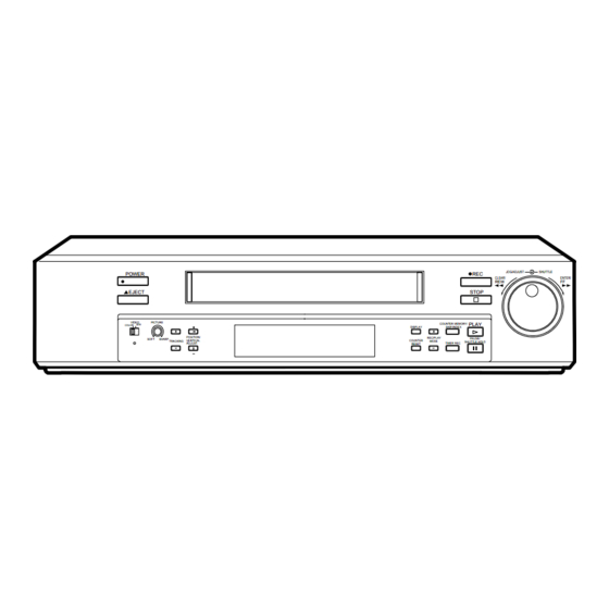
Page 4: Features And Functions
FEATURES AND FUNCTIONS FRONT VIEW JOG/ADJUST SHUTTLE POWER CLEAR/ ENTER/ EJECT STOP VIDEO PICTURE PLAY COUNTER MEMORY/ COLOR DISPLAY SKIP/INDEX POSITION/ REC/PLAY SOFT SHARP PAUSE/ VERTICAL COUNTER TRACKING MODE SHUTTLE HOLD TIMER REC ADJUST RESET Fluorescent display 1 POWER button (Press for on; press again for off) B TIMER REC button The POWER indicator illuminates when the VCR is This button is pressed when a timer recording is to be... -
Page 5: Fluorescent Display
FLUORESCENT DISPLAY M PL ALARM INDEX MODE SP LP SKIP EMGCY PLAY LOCK 1 M (COUNTER MEMORY) indicator 9 Cassette status indicator Illuminates during rewind for counter memory mode. Illuminates when tape is inserted. The light advances, stops or flashes corresponding to the movement of the 2 PL (POWER LOSS) indicator tape. -
Page 6: Rear View
REMOTE AUDIO VIDEO The VCR illustrations appearing in this manual are of the HS-7496E(B). • Ensure the power cord is not plugged into the mains outlet before connecting to any rear terminals. 1 AC power socket 8 CLK (CLOCK) OUT terminal This socket connects to the power cord. -
Page 7: Connecting With Other Equipment
CONNECTING WITH OTHER EQUIPMENT CCTV CAMERA VIDEO SET IN VIDEO SENSOR REC GND ALM MODE CLK CALL RESET ÉMIC REMOTE AUDIO VIDEO MIC IN AUDIO VIDEO VIDEO IN AUDIO IN MONITOR VERTICAL ADJUSTMENT (Correcting picture vibration at the top and bottom) The picture vibration can be reduced or eliminated by the following steps. -
Page 8: Setting The Menus
SETTING THE MENUS The operating parameters of this VCR are set through various on-screen menus. Set the menus as follows: OPERATION 1 Press the DISPLAY button. • The “MAIN MENU” is displayed. 2 Turn the JOG dial to select the desired item. •... - Page 9 1 DISPLAY MAIN MENU Sets the display format of the date and present time on the monitor. 2 TIME DATE SEARCH <MAIN MENU> Sets the date, time and direction to search for the desired part of a tape. DISPLAY TIME DATE SEARCH 3 TIMER PROGRAM TIMER PROGRAM RECORDING SET UP...
- Page 10 SETTING THE MENUS RECORDING SET UP <RECORDING SET UP> ALARM REC MODE 1 SETTING THE ALARM REC MODE (ALARM REC MODE) ALARM REC DURATION EMERGENCY REC Sets the alarm recording time mode. When the JOG dial is turned, the display will be switched in the order of 3H } 6H } L18H } 3H } ..
- Page 11 MAINTENANCE <MAINTENANCE> POWER LOSS LIST 1 DISPLAYING THE POWER LOSS LIST (POWER LOSS LIST) ALARM LIST Turn the JOG dial to select “POWER LOSS LIST”. Turn the SHUTTLE ring to the right to display the ALL MENU INITIALIZE POWER LOSS LIST CLEAR Power Loss List.
-
Page 12: Setting The Present Time
SETTING THE PRESENT TIME ACCURATELY PRESET THE DAY AND PRESENT TIME BEFORE TIMER PROGRAMMING <Display mode 1> 1 Day-Month-Year 2 Hour : Minute : Second 3 Daylight saving time symbol or power failure symbol 4 Alarm recording number 01-01-98 00:00:00 A0001 •... - Page 13 6 Setting the daylight saving time < TIME DATE ADJUST > DAYLIGHT SAVINGS To put the clock forward 1 hour, set DAYLIGHT SAVINGS to ON. MONTH Turn the SHUTTLE ring to the right. The DAYLIGHT SAVINGS display will flash. DATE YEAR Turn the JOG dial to select “OFF”...
-
Page 14: Loading And Unloading The Cassette Tape
LOADING AND UNLOADING THE CASSETTE TAPE Video cassette tapes can be loaded into your new VCR as long as the VCR is plugged into a power source. Even if the VCR power switch is turned off, loading a cassette will automatically cause it to turn on. Use only video cassette tapes marked V Use only standard grade VHS cassette tapes for reliable video recording. -
Page 15: Manual Recording
MANUAL RECORDING JOG/ADJUST SHUTTLE POWER CLEAR/ ENTER/ EJECT STOP VIDEO PICTURE PLAY COUNTER MEMORY/ COLOR DISPLAY SKIP/INDEX POSITION/ REC/PLAY SOFT SHARP PAUSE/ VERTICAL COUNTER TRACKING MODE SHUTTLE HOLD ADJUST TIMER REC RESET LOCK button 1 Load a cassette with the erasure prevention tab intact. 2 Press the REC/PLAY MODE (-) or (+) buttons to select the desired recording mode. -
Page 16: Repeat Recording
MANUAL RECORDING REPEAT RECORDING When the “TAPE END” of the “FIRST TIME SET UP” menu is set to “REPEAT” or “ALARM•PROT” and the repeat recording mode is set (the REPEAT indicator is illuminated), the tape will automatically be rewound to the start when the tape end is reached. Then recording will start again. -
Page 17: Synchronous Recording
SYNCHRONOUS RECORDING A number of camera images can be mixed together through a camera switcher and then recorded separately onto several VCRs. A camera is assigned to each VCR with the VCR recording only the camera image it has been assigned. This allows recording without gaps. -
Page 18: Additional Features
ADDITIONAL FEATURES COUNTER MEMORY Press the COUNTER MEMORY/ SKIP/ INDEX button repeatedly until the “M” indicator appears on the fluorescent display. Turn the SHUTTLE ring to the right and the tape will rewind to the “00000” position of the counter and stop. (The rewind to “00000” is slightly inaccurate.) The counter display is stored in the memory when the power is turned off, so the same numbers will be displayed when the power is turned back on. -
Page 19: Timer Recording
TIMER RECORDING • “DAY” (in “Day of the week”) is used for the same time recording everyday. • “SPL” (special) (in “Day of the week”) indicates <TIMER PROGRAM> that the recording period set in “TIMER START PROGRAM” display becomes available. 1 - - - - - : - - - - : - -... -
Page 20: Timer Recording
TIMER RECORDING SPECIAL DW SETTINGS Set the recording period by specifying the start and end day of the week for timer recording. 1. Display the “TIMER PROGRAM” setting display. 2. Turn the JOG dial to select “SPECIAL DW” and turn the SHUTTLE ring to the right. 3. -
Page 21: Alarm Recording
ALARM RECORDING It is possible to switch from all recording modes to the 3H - L18H recording mode by applying an alarm signal to the SET IN terminal on the rear panel. ALARM SET INPUT • It is possible to switch to the alarm recording by applying the set signal from the alarm sensor 3H or 6H 3H - 96H... -
Page 22: Setting For Alarm Recording
ALARM RECORDING SETTING FOR ALARM RECORDING Alarm recording is used to activate more rapid recording when the VCR is recording in one of the Time Lapse modes. Alarm recording provides for more pictures during the alarm duration. Emergency recording enables alarm recording even if the VCR is off, stopped or in timer recording/stand-by. -
Page 23: Alarm Recording 20
ALARM RECORD TIME DISPLAY When alarm recordings begin, the start times are stored in the memory so it is possible to < ALARM LIST > confirm when they have occurred. Select the “ALARM LIST” in the “MAINTENANCE” menu and 0001 05 - 01 - 98 01 : 00 0002 07 - 01 - 98 21 : 10... -
Page 24: Playback
PLAYBACK JOG/ADJUST SHUTTLE POWER CLEAR/ ENTER/ EJECT STOP VIDEO PICTURE COUNTER MEMORY/ PLAY COLOR DISPLAY SKIP/INDEX POSITION/ REC/PLAY PAUAE SOFT SHARP VERTICAL TRACKING COUNTER MODE SHUTTLE HOLD TIMER REC ADJUST RESET 1 Load a prerecorded tape. AUTO PLAY: If a cassette with the erasure prevention tab removed is loaded, the unit automatically begins playback mode. 2 Press the REC/PLAY MODE (+) or (-) button to select the desired playback mode. -
Page 25: Special Effects Playback
SPECIAL EFFECTS PLAYBACK The following convenient functions are available. Audio output is muted during special effects playback. SHUTTLE RING You can adjust the speed by using the SHUTTLE ring. 1/30 1/30 1 Press the PLAY button to begin playback. 1/15 1/15 2 Press the PAUSE/SHUTTLE HOLD button to obtain a still picture. -
Page 26: Adjustment During Playback
ADJUSTMENT DURING PLAYBACK TRACKING ADJUSTMENT If noise appears in the picture during playback, fast playback, reverse playback or forward/reverse slow playback, adjust the TRACKING buttons to achieve the best picture. If noise appears. POSITION/ POSITION/ TRACKING TRACKING VERTICAL VERTICAL ADJUST ADJUST For tracking adjustment at fast playback, reverse playback or forward/reverse slow playback mode, press the PAUSE/ SHUTTLE HOLD button while turning and holding the SHUTTLE ring. -
Page 27: Warning Display
WARNING DISPLAY SELF DIAGNOSTIC FUNCTION The VCR uses a self diagnostic function to detect internal malfunctions during recording. Should a malfunction occur during record- ing, a corresponding indication appears on the monitor screen and the fluorescent display. The type of malfunction corresponding to the indication, and countermeasures, are given below. Fluorescent CAUSE Monitor... -
Page 28: Before Calling For Service
BEFORE CALLING FOR SERVICE Symptom Remedy • Is the LOCK indicator illuminated? VCR does not operate. • Has the power cord been disconnected from the AC outlet? • Is the TIMER REC indicator illuminated? The VCR POWER is ON but unit does •... -
Page 29: Control Input/Output Signals And Circuits
CONTROL INPUT/OUTPUT SIGNALS AND CIRCUITS 2 SET/ RST/ REC IN terminals (screw) Active: When input terminals are short-circuited to GND or “L” level voltage (0 - +1.6V) applied. Time for active: 0.1 sec or over. Non active: Open the input. DC5V SET/RST/REC IN 0.047 F... - Page 30 CONTROL INPUT/OUTPUT SIGNALS AND CIRCUITS 2 REMOTE jack Circuit Shielded cable 2 ···································· 31 1) Resistor R: Metal film resistor 1/4W 33kohms ±1%, temperature factor ±100ppm/°C. 2) Button switch: Momentary, ON resistor 200ohms or under. 3) Connector MJ: Miniature jack, 2.5mm in diameter, comply with JISC6560. Operational conditions 1) Isolation resistor: 200Mohms or over (in connector MJ)
-
Page 31: Specifications
SPECIFICATIONS Tape Format: VHS 1/2" width high-density video cassette tape. Power Source: AC100-230V (HS-7496E(B), HS-7496EM(B)), AC100-240V (HS-7496E(A)), 50/60Hz Power Consumption: Approx. 20 watts. Television System: 625 lines, 50 field PAL-type colour system. Video Recording System: 2 rotary heads, azimuth helical scanning system. - Page 32 872C190D8 PRINTED IN JAPAN...