Table of Contents
Advertisement
Quick Links
Advertisement
Table of Contents
Troubleshooting

Related Manuals for Sharp AR-3551


Summary of Contents for Sharp AR-3551
-
Page 2: Trademark Acknowledgments
All information included herein is subject to change without notice. SHARP is not responsible for any loss or damages, direct or indirect, arising from or related to the use of this operation manual. -
Page 3: Installation Requirements
INSTALLATION REQUIREMENTS Improper installation may damage this product. Please note the following during initial installation and whenever the machine is moved. 1. The machine should be installed near an accessible power outlet for easy connection. 2. Be sure to connect the power cord only to a power outlet that meets the specified voltage and current requirements. -
Page 4: Cautions
INSTALLATION REQUIREMENTS Moving this machine Lift this machine at the positions shown in the illustration below and carry it horizontally. CAUTION Two people are required to lift and carry this machine. The center of gravity of the machine is slightly to the left of the center of the machine when viewed from the front. If a duplex module is installed the center of gravity will be even further shifted to the left. - Page 5 CAUTIONS 1. Do not touch the photoconductive drum. Scratches or smudges on the drum will cause dirty prints. 2. The fusing unit is extremely hot. Exercise care in this area. 3. Do not look directly at the light source of the scanner module.
-
Page 6: Cautions On Laser
CAUTIONS Cautions on laser Wave length +10 nm 785 nm −15 nm Pulse times North America: 35 cpm model: (4.1 µs ± 4.1 ns)/7 mm 45 cpm model: (5.7 µs ± 5.7 ns)/7 mm Europe: 31 cpm model: (3.8 µs ± 3.8 ns)/7 mm 35 cpm model: (3.8 µs ±... - Page 7 CAUTIONS For Europe: CAUTION VAROITUS! INVISIBLE LASER RADIATION LAITTEEN KÄYTTÄMINEN WHEN OPEN INTERLOCKS MUULLA KUIN TÄSSÄ CLASS 1 LASER PRODUCT DEFEATED. AVOID EXPOSURE KÄYTTÖOHJEESSA TO BEAM. MAINITULLA TAVALLA SAATTAA ALTISTAA KÄYTTÄJÄN VORSICHT LASER KLASSE 1 TURVALLISUUSLUOKAN 1 UNSICHTBARE YLITTÄVÄLLE LASERSTRAHLUNG WENN NÄKYMÄTTÖMÄLLE ABDECKUNG GEÖFFNET UND LUOKAN 1 LASERLAITE...
-
Page 8: Facsimile Feature
FACSIMILE FEATURE To extend the capabilities of this product to include facsimile functions, an optional facsimile expansion kit must be installed. Refer to the facsimile operation manual for details on using the facsimile features. Line connector ■ ■ ■ ■ ■ Line connection Use the telephone cable supplied with the facsimile expansion kit to TE L connect the machine to a telephone line. -
Page 9: Table Of Contents
CONTENTS Page INSTALLATION REQUIREMENTS ... . 0-1 CHAPTER 2 ● Carrying this machine ....0-2 PRINTING FROM A COMPUTER CAUTIONS . -
Page 10: Contents
CONTENTS SADDLE STITCH FINISHER ....5-17 CHAPTER 4 ● Part names ......5-17 TROUBLESHOOTING AND ●... -
Page 11: Before Using The Product
CHAPTER 1 BEFORE USING THE PRODUCT This chapter describes basic information that should be read before using this product. Page INTRODUCTION ..................1-2 MAIN FEATURES ..................1-3 PART NAMES AND FUNCTIONS ............1-4 ● Exterior ....................1-4 ● Interior ....................1-5 ●... -
Page 12: Introduction
INTRODUCTION To gain the maximum benefits in using this product, it is recommended that the user read this manual to become familiar with all the features and functions of the basic product and the precautionary information contained in the manual. NOTE In this manual, American spellings are used. -
Page 13: Main Features
NERGY ® The preheat mode is the first level of power reduction. The power is reduced Partner, SHARP has to the fuser unit a preset time after the machine has completed a job and no determined that this further machine operations have been made. The machine can recover to... -
Page 14: Part Names And Functions
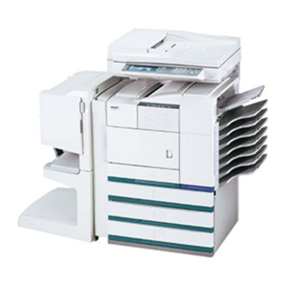
PART NAMES AND FUNCTIONS Exterior Bypass tray paper guide Front cover Open to add toner . Exit tray* Main switch Press to turn power on and off. Duplex module/bypass tray* Module for two-sided printing Paper tray 1 Upper paper output area Stand/3 x 500 sheet paper drawer* (See page 1-23.) Finished sheets are deposited here. -
Page 15: Interior
PART NAMES AND FUNCTIONS Interior Duplex module side cover Toner cartridge (drum/toner cartridge)* Open when a misfeed has occurred in the duplex The toner cartridge must be replaced when indicated module. on the operation panel. Side cover latch Photoconductive drum Push up to open the side cover when a misfeed has Images are formed on the photoconductive drum. -
Page 16: Part Names And Functions Of Peripheral Devices
PART NAMES AND FUNCTIONS Part names and functions of peripheral devices... - Page 17 PART NAMES AND FUNCTIONS B/W scanner module/DSPF (AR-EF1) Multi purpose drawer (AR-MU1) Up to 500 sheets of 20 lbs. (80 g/m The B/W scanner module/DSPF is a monochrome ) paper can be scanner that uses two scanning modes. In one mode, loaded.
- Page 18 PART NAMES AND FUNCTIONS ■ ■ ■ ■ ■ Other optional equipment ● Scanner rack (AR-RK1) ● Hard disk drive (AR-HD3) This rack is required to support the scanner module Extends the image storing capacity for the printer above the printer. and copier features.
-
Page 19: Operation Panel Of The Main Unit
PART NAMES AND FUNCTIONS Operation panel of the main unit The display and indicators show the current status of the printer. All printer settings are made by using the keys and display panel. Message display [ / ] keys Displays the current status of the printer. Press to select menu or function items or to set [ i ] displayed in any message indicates that the numerical values for those items. - Page 20 PART NAMES AND FUNCTIONS Menu group and explanation of the use of the keys on the main unit operation panel The menu groups are classified into five groups and are selected consecutively by pressing the [MENU] key. If the [OK] key is pressed when the desired menu screen is displayed, a message will appear to indicate the next required operation.
- Page 21 PART NAMES AND FUNCTIONS Canceling a print job and deleting print data ● ● ● ● ● To cancel a print job in progress and delete the print data: Press the [BACK/C] key during printing. Printing will stop and a message asking for confirmation to delete the job will appear.
-
Page 22: Operation Panel Of The Scanner Module
PART NAMES AND FUNCTIONS Operation panel of the scanner module When the printer is equipped with a scanner module, the operation panel on the main unit will become inoperative and the panel on the scanner module must be used. Touch panel The machine status, messages and touch keys are [JOB STATUS] key displayed on the panel. -
Page 23: Touch Panel (On The Scanner Module)
This screen is displayed when the print mode is selected. (The display varies with the mode. For the display in other modes, see their respective operation manuals.) SELECT JOB. PRINT HOLD JOB LIST Sharp 005 Microsoft Word - Test001 Sharp 006 EXCEL1... -
Page 24: Contents
PART NAMES AND FUNCTIONS Job status screen (common to print, copy, network scan, and fax modes) This screen is displayed when the [JOB STATUS] key on the operation panel is pressed. A job list showing the current job at the top of the job queue or a list showing completed jobs can be displayed. The contents of the jobs can be viewed, moved up to the highest priority in the job queue or deleted from the queue. - Page 25 PART NAMES AND FUNCTIONS Using the touch panel ■ ■ ■ ■ ■ How to use the touch panel ■ ■ ■ ■ ■ Selection of function [Example 1] [Example 1] Items on the touch panel JOB QUEUE SETS / PR are easily selectable by 010 / 000 WAITING...
-
Page 26: Loading Paper
Do not use curled or folded paper. Doing so may cause a misfeed. ● For best results use paper supplied by SHARP. (See page 1-18.) ● When you change the paper type and size in paper tray 1, set the paper type and size referring to “Setting the paper size and type”... -
Page 27: Specifications Of Paper Trays
LOADING PAPER Specifications of paper trays The specifications for types and sizes of paper for loading paper trays are shown below. Paper Tray No. Applicable paper types Applicable paper sizes Tray (tray name) weight 16 to 28 lbs. Plain paper (Refer to the next Paper tray 1 Tray 1 ●... - Page 28 For 5-1/2 x 8-1/2 or A5 paper, the orientation must be landscape. ● Transparency film, labels, Use SHARP recommended paper. Do not use labels other and tracing paper than SHARP recommended labels. Doing so may leave adhesive residue in the printer, causing paper misfeeds, smudges on prints or other machine trouble.
-
Page 29: Setting The Paper Size And Type
LOADING PAPER Setting the paper size and type For the specifications for types and sizes of paper for loading paper trays, see page 1-17. Setting the paper size and type from the operation panel on the main printer When the paper size or type is changed in a paper tray, set them referring to the following procedure. Press the [MENU] key repeatedly until Press the [OK] key. - Page 30 LOADING PAPER Setting the paper type and size from the touch panel Press the [CUSTOM SETTINGS] key. “AUTO-INCH”: Select when you have set inch system paper. When the paper system is changed from the inch The custom setting menu system to the AB system or vise versa, the paper screen will appear.
-
Page 31: Loading Paper In The Multi Purpose Drawer
LOADING PAPER Loading paper in the multi purpose drawer The method of loading paper into the multipurpose drawer is the same as for paper tray 1 described on page 1-16. For specifications of paper, see page 1-17. When loading envelopes, postcards or transparency film, follow the descriptions below. - Page 32 LOADING PAPER Printing onto envelopes ● Do not use envelopes that have metal clasps, plastic snaps, string closures, windows, linings, self-adhesive patches or synthetic materials. Attempting to print on these may cause misfeeds, inadequate toner adherence or other trouble. ● Envelopes of which the surface is not flat because of embossing may cause the prints to become smudges.
-
Page 33: Specifications (Multi Purpose Drawer)
Middle and lower paper trays: Up to 500 sheets of SHARP recommended plain paper can be loaded in these trays. The method of loading paper is the same as for paper tray 1 in the main unit. See the description (page 1-16). -
Page 34: Loading Paper In The Stand/Mpd & 2000 Sheet Paper Drawer
LOADING PAPER Loading paper in the stand/MPD & 2000 sheet paper drawer Upper paper tray: The upper paper tray is equivalent to the multi purpose drawer. The method of loading paper and the paper that can be used are the same as for the multi purpose drawer. Refer to the description of the multi purpose drawer (see page 1-21). Lower paper tray: The lower paper tray is a large capacity tray that holds 2,000 sheets of 8-1/2"... -
Page 35: Adding Toner
* For some models, developer cartridges are not replaced by users. For best copying results, be sure to use only Sharp Genuine Supplies which are designed, engineered, and tested to maximize the life and performance of Sharp products. Look for the Genuine Supplies label on the toner package. - Page 36 1-26...
-
Page 37: Printing From A Computer
CHAPTER 2 PRINTING FROM A COMPUTER This chapter describes how to install and how to use the printer drivers and printer utilities on a computer. This chapter also describes the job retention function that allows a print start operation from the operation panel of the printer. -
Page 38: Connecting To A Computer
CONNECTING TO A COMPUTER 1. Using this machine as a local printer When using this machine as a local printer, connect your computer to the parallel interface connector as shown in the illustration. The cable is not supplied with the printer. A shielded cable which conforms to both the printer specifications and your computer specifications must be obtained. -
Page 39: Installing Printer Drivers And Printer Utilities
INSTALLING PRINTER DRIVERS AND PRINTER UTILITIES Windows software The following software can be installed from the installer PCL printer drivers supplied in the CD-ROM : PCL display font Windows client PCL printer drivers (PCL5e and PCL6) ● Network administrator Printer Status Network Administration Utility ●... -
Page 40: Installing Printer Drivers Using Plug & Play Or The "Add Printer Wizard
INSTALLING PRINTER DRIVERS USING PLUG & PLAY OR THE “ADD PRINTER WIZARD” Before installation Before installing the printer drivers, check the following items. Ensure that your computer system meets the following requirements. ● Computer type: Operating system: IBM PC/AT or compatible computer Windows 95 Hardware requirements of the operating system must Windows 98... -
Page 41: Setting The Printer Driver
SETTING THE PRINTER DRIVER This section describes the method of changing the printer driver settings from your computer. If no printer driver has been installed, use the supplied CD-ROM to install it referring to “INSTALLING PRINTER DRIVERS AND PRINTER UTILITIES” on page 2-3. Printer driver settings under Windows (selecting and setting print conditions) Change the settings using the printer properties. -
Page 42: Printer Configuration Through The Network
PRINTER CONFIGURATION THROUGH THE NETWORK If you access the Web pages of this product from your computer using a Web browser such as Netscape Navigator and Internet Explorer, various settings can be adjusted through the network. Environment required for accessing Web pages The following products and computer system requirements are needed for accessing the Web pages of this product. -
Page 43: Printer Configuration Through The Network
PRINTER CONFIGURATION THROUGH THE NETWORK Items and outline of menu frame of Web pages Destination Management The basic screen on which you can add, modify, or delete the destinations for image data scanned by the network scanner. The recipient information for facsimile and Internet facsimile features (destination address, facsimile number, etc.) is described below. - Page 44 PRINTER CONFIGURATION THROUGH THE NETWORK Access setup The restriction on access to the Web pages and basic settings for using the network scanner and the status/alert E- mail function are described below. ■ ■ ■ ■ ■ Network Card Setup A link to the network card Web page for configuring the print server card (network interface card) is provided.
-
Page 45: Job Control
JOB CONTROL This section describes the operation procedure required for “JOB CONTROL”. To use job control in your print job, select “Properties” on the printer driver screen, open the “Main” tab, and click “Job control.” The job hold function can be used only if your printer is equipped with the hard disk drive option. -
Page 46: Hold Job List
JOB CONTROL Hold job list If “Print after hold”, “Print before hold” or “Proof print” operation is performed on the computer, print data will be held as a hold job. (Up to 100 jobs can be held. If the main switch is turned off, the stored data of all jobs in hold will be cleared.) If the number of jobs exceeds 100, the job is processed as follows. - Page 47 JOB CONTROL Verify that the desired number of copies is set. The number of copies can COPIES be changed by using the 10SET key on the operation panel. Press the [OK] key. ● Printing will start. If printing of another job is being executed, however, your job will be registered as a print job.
-
Page 48: Printer Account Control
JOB CONTROL Printer account control If the key operator program “Auditing mode” is set, the number of printed pages can be accumulated for each account. The accounts for auditing are the accounts that have been set for counting the number of pages for the printer with a key operator program. -
Page 49: Using The Machine As A Postscript Printer
USING THE MACHINE AS A POST- SCRIPT PRINTER If an optional PS3 expansion kit (AR-PK1) is installed, this machine can be used as a PostScript compatible printer. The machine can be used in the Macintosh environment as well as in the Windows environment when used as a PostScript printer. - Page 50 USING THE MACHINE AS A POSTSCRIPT PRINTER ■ PS display font The PRINTER UTILITIES CD-ROM of a PS3 expansion kit contains PS display fonts. Install the PS display fonts as needed when the PostScript printer driver is installed. To install the PS display fonts, select it when installing the PostScript printer driver using the installer.
-
Page 51: Using The Printer In The Macintosh Environment
■ SHARP PPD Utility The SHARP PPD Utility is used to register account numbers and passwords when the auditing mode (page 6-7) or the job retention function with password (page 2-9) is used. This utility is also used to change the registered account numbers and passwords. - Page 52 Turn on the computer and start the Click the [Install] button of step 4. operating system. The SHARP Installer dialog box will appear. Ensure that “Easy Install” is selected, select the drive, and click the [Install] button. Insert the supplied SHARP PS3 Expansion...
- Page 53 USING THE MACHINE AS A POSTSCRIPT PRINTER ■ Selecting the printer Follow the procedure below to select the printer. Click ‘Create’, ‘Setup’ or ‘Setup...’. Ensure that the printer is connected to the network to which your computer is (Phrase depends on the version of MAC OS installed) ●...
- Page 54 USING THE MACHINE AS A POSTSCRIPT PRINTER ■ Paper setting Select “Page Setup” from the [File] menu Adjust each setting. of application software. ● Paper size, reduction/enlargement, and orientation can be set. The following display will appear. (The display varies with the operating system versions, printer driver Click the [OK] button.
- Page 55 Before using the printer auditing mode or the job retention function with password from a Macintosh computer, you must use the PPD Utility to register account numbers and passwords. The PPD Utility is installed together with the PPD files using the installer for Macintosh contained in the SHARP PS3 Expansion Kit AR-PK1 PRINTER UTILITIES CD-ROM.
-
Page 57: Printer Basic Settings
CHAPTER 3 PRINTER BASIC SETTINGS This chapter describes the following items. 1. Printer configuration settings 2. Custom settings based on the customer’s operating conditions. Page MAKING CONFIGURATION SETTING ........... 3-2 ● Operation procedure common to all printer configuration settings (items that can be set from the operation panel) ......3-2 ●... -
Page 58: Making Configuration Setting
MAKING CONFIGURATION SETTING The printer configuration setting allows basic printer settings to be made. The items set with the printer configuration settings are shown below. ● Default settings ........ Basic settings used in printing (See page 3-4.) ● PCL settings ........Sets a PCL symbol set. (See page 3-5.) ●... -
Page 59: Pcl Settings
MAKING CONFIGURATION SETTING When the machine is being operated from the touch panel on a scanner module: Touch the [CONDITION SETTINGS] key on Touch the desired setting on the setting the printer screen to display the screen of the desired item and touch the configuration setting menu screen. -
Page 60: Default Settings
MAKING CONFIGURATION SETTING Default settings The default settings allow detailed print conditions to be set for printing without any printer driver (for example, printing from MS-DOS and printing from a computer without any printer driver installed). The setting items are shown below. NOTE When some items can be set both in the printer driver and on the operation panel, the values set in the printer driver override those set on the operation panel. -
Page 61: Pcl Settings
MAKING CONFIGURATION SETTING ■ ■ ■ ■ ■ Line thickness This setting is used to adjust the line width of vector graphics. For example, if you desire a finer line, select a value from 0 to 4. If you desire a thicker line, select a value from 6 to 9. To return to the standard line thickness, select 5. Use this setting for special applications such as CAD when lines do not appear with sufficient clarity. -
Page 62: Custom Settings
CUSTOM SETTINGS Custom settings are used for various settings based on the customer operating conditions. The items that can be set with the custom settings are shown below. ● Total count ........The number of printed pages and the like are displayed. (See page 3-8.) ●... -
Page 63: Setting Items
CUSTOM SETTINGS When setting is complete, press the Press the [OK] key. [MENU] key to return to the basic screen. “ ” will be displayed to the right of selected item, and the setting will be reg- NOTE istered. Depending on the If the [BACK/C] key is pressed after each setting setting item, additional is complete, the display that has called the setting... -
Page 64: Setting Items
CUSTOM SETTINGS Setting items ■ ■ ■ ■ ■ Total count ■ ■ ■ ■ ■ Tray settings The number of total printed pages in this product Paper type, paper size, operation mode, and use of can be displayed and printed. automatic tray switching are set for each tray. -
Page 65: Troubleshooting And Maintenance
CHAPTER 4 TROUBLESHOOTING AND MAINTENANCE This chapter describes misfeed removal, user maintenance, etc. Page MISFEED REMOVAL ......... 4-2 ●... -
Page 66: Misfeed Removal
MISFEED REMOVAL When the machine is being operated from the operation panel on the main unit: ● If the machine is not equipped with a scanner, all messages will appear on the display panel of the main unit. For machines equipped with a scanner, messages will appear on the touch panel display on the scanner module. When a misfeed has occurred, printing will stop and the message shown below will appear. -
Page 67: Misfeed Removal Guidance
MISFEED REMOVAL When the machine is being operated from the touch panel on a scanner module: When a misfeed has occurred during printing, the message “A MISFEED HAS OCCURRED.” will appear in the touch panel display of the operation panel and printing including copying and facsimile output will stop. The approximate misfeed locations are indicated with “... -
Page 68: Misfeed In The Paper Feed Area
MISFEED REMOVAL Misfeed in the paper feed area NOTE Be sure to follow the misfeed removal sequence. Do not pull the paper tray out first as paper may be located between the paper tray and the paper feed section. If the tray is pulled first, the misfed paper may be torn and difficult to remove. - Page 69 MISFEED REMOVAL ■ Misfeed in the stand/3 x 500 sheet paper ■ ■ ■ ■ ■ Misfeed in the multi purpose drawer drawer Unlatch the duplex module and slide it to For misfeed removal in the upper tray, follow the the left.
-
Page 70: Misfeed In The Transport Area, Fusing Area, And Exit Area
MISFEED REMOVAL Misfeed in the transport area, fusing area, and exit area CAUTION If paper is misfed in the The fusing unit is hot. Take care in removing paper. fusing area, turn roller (Do not touch the metal parts.) rotating knob B in the direction of the arrow to remove the misfed paper. -
Page 71: Misfeed In The Duplex Module
MISFEED REMOVAL Misfeed in the duplex module Unlatch the duplex module and slide it to Gently close the duplex module. the left. After closing the duplex module, confirm that the Unlatch the unit and misfeed message has gently move the module been cleared and the away from the machine. -
Page 72: Troubleshooting
TROUBLESHOOTING Whenever the printer stops or operation is not possible, check the operation panel display for messages. In most cases these messages will give sufficient information to return the machine to an operating condition. In cases where this information is not enough, check the list below for more information. This section describes problems concerning printer features. - Page 73 TROUBLESHOOTING Problem Check Solution or cause Black pages ● Is a color on color image being Some color on color images may be printed? printed as all black. ● Negative image printing? Check print driver setting. Black and white areas are reversed.
- Page 74 TROUBLESHOOTING Problem Check Solution or cause Smudges on printed ● See the Operation Manual (Read this Is a message indicating a need of sheets document before installing the product.). maintenance or replacement of developer cartridge displayed ([ERROR] indicator on the main unit operation panel lit)? ●...
-
Page 75: User Maintenance
USER MAINTENANCE To ensure good service from this product over a long period of time, it is recommended that the following maintenance be performed on a regular basis. NOTE When cleaning, do not use thinner, benzene, or similar volatile cleaning agents. Cleaning the scanner module If the document glass, DSPF scanning section glass or document cover have dirty spots, these spots will become part of scanned images. -
Page 77: Peripheral Devices
CHAPTER 5 PERIPHERAL DEVICES This chapter describes operating instructions for the Mail-Bin Stacker, the Finisher, the Saddle Stitch Finisher, and the Duplex Module. Page DUPLEX MODULE ................... 5-2 ● Part names ..................5-2 ● Specifications ..................5-2 ● Loading paper in the bypass tray ............5-3 ●... -
Page 78: Duplex Module
DUPLEX MODULE If a duplex module is installed, printing onto both sides of paper can be performed. Two types of duplex modules are available: duplex module/bypass tray and duplex module. The descriptions in this manual are for the duplex module/bypass tray. For misfeed removal for these modules, see page 4-7. Part names Exit tray Duplex module... -
Page 79: Loading Paper In The Bypass Tray
When printing onto transparency film, remove ● the output sheets as soon as possible. ● For transparency film, use SHARP recom- mended film. Set the type and size of the loaded paper. When the paper system is changed from the inch... -
Page 80: Setting The Printer Driver For Duplex Module, Bypass Tray And Exit Tray
DUPLEX MODULE Setting the printer driver for duplex Copying in the duplex mode module, bypass tray and exit tray For copying in the duplex mode, press the COPY key on the operation panel and make all selections on the When using the duplex module (including the bypass copy mode basic screen. -
Page 81: Troubleshooting (Concerning The Duplex Module)
DUPLEX MODULE Troubleshooting (concerning the duplex module) Check the list below before calling for service. Problem Check Solution or cause Message indicating the paper type cannot Special paper cannot be used for two-sided The printer will not be used for two-sided printing displayed? printing. -
Page 82: Mail-Bin Stacker
MAIL-BIN STACKER The mail-bin stacker has 7 mail bins which can each be designated to receive printed output from a user or a group of users . Output paper in the copy mode and the fax mode will be delivered to the top tray of the stacker separated from printed output. -
Page 83: Specifying Mail Bins To Receive Printed Output
MAIL-BIN STACKER Specifying mail bins to receive printed output Printed output can be specified in the printer driver to be delivered to an assigned mail bin or to the top tray. Assigning mail bins to individual users or groups of users reduces the mixing of print jobs simplifying the retrieval of printed output. -
Page 84: Misfeed In The Mail-Bin Stacker
MAIL-BIN STACKER Misfeed in the mail-bin stacker If a misfeed has occurred in the mail-bin stacker during printing, remove the misfed paper following the procedure below. Open the top cover. Remove the misfed paper. Move the release lever in Be careful not to tear the Top cover the direction of the arrow misfed paper during... -
Page 85: Finisher
FINISHER The finisher can deliver collated sets either stapled or unstapled. Unstapled sets can be offset stacked from the previous set for easy separation of the sets. Part names Top tray Latch Printer, copier and fax Release the latch to open the output finisher for misfeed removal. -
Page 86: Finisher Functions
FINISHER Finisher functions ■ ■ ■ ■ ■ Sort mode ■ ■ ■ ■ ■ Group mode Sorted sets will be delivered. Groups of prints or copies of the same page will be delivered. Original Printouts Original Printouts ■ ■ ■ ■ ■ Offset mode Offset mode Non-offset mode Sets will move from side to side so that each set or... -
Page 87: Using The Finisher Functions
FINISHER Using the finisher functions ■ ■ ■ ■ ■ Selecting the stapling function from a printer driver. Select “Properties” on the printer driver setting screen The illustration below shows the screen for a PCL printer and open the “Main” tab. Select “Left”, “Right” or “Top” driver in the Windows 98 environment as an example. -
Page 88: Staple Cartridge Replacement
FINISHER Staple cartridge replacement When the staple cartridge becomes empty, the message “Add staples.” will appear in the message display of the operation panel. Follow the procedure below to replace the staple cartridge. Open the front cover. NOTES ● Do not remove the tape from the cartridge before inserting the staple cartridge into the box. - Page 89 FINISHER ■ ■ ■ ■ ■ Checking the staple unit If the message “CHECK THE STAPLER UNIT” or “CHECK STAPLER POSITION OR STAPLE JAM” appears, follow the procedure below. Open the finisher compiler. Raise the lever at the end of the staple box. Release the latch to open Remove the top staple if the finisher compiler.
-
Page 90: Misfeed In The Finisher
FINISHER Misfeed in the finisher When a misfeed occurs in the finisher, remove the misfed paper following the procedure below. Remove the misfed paper from the output Raise the paper guide and remove the area. misfed paper. Do not remove paper from Be careful not to tear the Paper the stapler compiler. -
Page 91: Troubleshooting Finisher Problems
FINISHER Troubleshooting finisher problems Check the list below before calling for service. Problem Check Solution or cause Stapling position not set correctly? Stapling position is Check the stapling position setting. (See page not correct. 5-16.) The finisher does Are any finisher covers open? Close all covers. -
Page 92: Stapling Position Quick Reference Guide For Duplex Output
FINISHER Stapling position quick reference guide for duplex output The orientation of the copy paper, original, scanned original data, and binding position selection are all interrelated. The table below shows these relationships. Orientation of original or original data Output result Page 1 &... -
Page 93: Saddle Stitch Finisher
SADDLE STITCH FINISHER The saddle stitch finisher can automatically place two staples for centerline binding of prints or copies and fold them along the centerline. An optional hole punching unit is available for installation into the finisher. Part names Stapler compiler Paper to be stapled is stacked Top cover temporarily. -
Page 94: Saddle Stitch Finisher Functions
SADDLE STITCH FINISHER 8-1/2" x 11" or A4 or smaller size: 50 sheets*(20 lbs. or 80 g/m Stapling capacity 8-1/2" x 14" or B4 or larger size: 25 sheets*(20 lbs. or 80 g/m *Up to two sheets of 34 lbs. or 128 g/m paper can be included as covers. -
Page 95: Staple Sort Mode
SADDLE STITCH FINISHER ■ Staple sort mode Collated sets of prints or copies will be stapled and delivered to the offset tray. When saddle stitching is selected, the prints or copies will be stapled at the center and delivered to the saddle stitch tray. The stapling positions, orientation, paper size for stapling, and stapling capacity are shown below. -
Page 96: Using The Saddle Stitch Finisher
SADDLE STITCH FINISHER Using the saddle stitch finisher ■ Selecting staple or saddle stitch from the printer driver. Select “Properties” on the printer driver setting The illustration below shows the screen for a PCL printer screen and open the “Main” tab shown in the driver in the Windows 98 environment as an example. -
Page 97: Staple Cartridge Replacement And Staple Jam Removal
SADDLE STITCH FINISHER [OK] key [SADDLE STITCH] key (See page 5-19.) When saddle stitching is selected, the copies will be Press to close the [OUTPUT] screen and to return stapled at the center and delivered to the saddle stitch to the basic screen. tray. - Page 98 SADDLE STITCH FINISHER Close the front cover. Insert the staple box. Push the staple box in until it clicks into place. NOTE Make a test print or copy in the staple sort mode to ensure that stapling is performed properly. Push the stapler section back into the finisher.
- Page 99 SADDLE STITCH FINISHER Turn roller rotating knob A in the direction Return the lever to its original position. of the arrow to move the staple unit to the front. Turn the roller rotating Roller rotating knob A knob until the triangle mark is aligned with the index.
-
Page 100: Misfeed In The Saddle Stitch Finisher
SADDLE STITCH FINISHER Misfeed in the saddle stitch finisher When a misfeed occurs in the saddle stitch finisher, remove the misfed paper following the procedure below. Unlatch the saddle stitch finisher and slide Close the top cover. it away from the printer. If saddle stitch was selected, open the front Remove the misfed paper from the main cover. - Page 101 SADDLE STITCH FINISHER Turn roller rotating knob in the direction of the arrow. Remove any misted paper from the saddle stitch tray. Be careful not to tear the misfed paper during removal. Close the saddle stitch section cover. Close the front cover. Push the saddle stitch finisher back against the printer.
-
Page 102: Troubleshooting (Concerning The Saddle Stitch Finisher)
SADDLE STITCH FINISHER Troubleshooting (concerning the saddle stitch finisher) Check the list below before calling for service. Problem Check Solution or cause Stapling position Stapling position not set properly? Check the stapling position setting. (See pages 5-27 and 5-28.) is not correct (including saddle stitch). -
Page 103: Stapling Position Quick Reference Guide For Duplex Output
SADDLE STITCH FINISHER Stapling position quick reference guide for duplex output The orientation of the copy paper, original, scanned original data, and binding position selection are all interrelated. The table below shows these relationships. Orientation of original or original data Output result Page 1 &... -
Page 104: Relation Between Print Image And Saddle Stitch
SADDLE STITCH FINISHER Relation between print image and saddle stitch The orientation of the copy paper, original, scanned original data, and binding position selection are all interrelated. The table below shows these relationships. Orientation of original or original data Output result Page 1 &... -
Page 105: Using The Key Operator Programs
CHAPTER 6 KEY OPERATOR PROGRAMS This chapter describes programs for use by the key operator. The key operator should read this chapter thoroughly to gain the maximum value these programs provide. Page KEY OPERATOR PROGRAMS ............... 6-2 ● Key operator program list ..............6-2 ●... -
Page 106: Key Operator Programs
KEY OPERATOR PROGRAMS KEY OPERATOR PROGRAMS This chapter describes the key operator programs concerning printer features and other programs common to printer, copier and facsimile features. These programs are provided for use by the key operator. For key operator programs specific to copier, facsimile or network scanner features, see the separate operation manuals for these features. -
Page 107: Using The Key Operator Programs
KEY OPERATOR PROGRAMS Using the key operator programs NOTE When using the key operator programs for the first time, register a key operator code number. (See steps 3 to 5 below or see steps 3 to 5 on page 6-6.) ●... -
Page 108: Structure Of The Setting Method For Key Operator Programs
KEY OPERATOR PROGRAMS Structure of the setting method for key operator programs The sequence for selection and setting of key operator programs are shown below. The [OK] and [BACK/C] keys allow navigation in either direction through the setting steps along a program setting path. Program steps start from the major categories shown at the left side of the chart and progress to the right. - Page 109 KEY OPERATOR PROGRAMS [OK] AUDITING MODE (OFF PRINT PER ACCOUNT DISPLAY [BACK/C] PRINT PER ACCOUNT PRINT PER ACCOUNT PRINT RESET ACCOUNT ACCOUNT NUMBER CONTROL ENTER NEW ACCOUNT NUMBER (5 digits) NO PRINT IF ACC'T # INVALID (NO [OK] DELETE ACCOUNT NUMBER CHANGE ACCOUNT NUMBER [BACK/C] PRINT ACCOUNT NUMBER...
- Page 110 KEY OPERATOR PROGRAMS When the machine is being operated from the touch panel on a scanner module: Press the [CUSTOM SETTINGS] key. Touch the key to select the desired major category of the key operator programs. <Example> ACCOUNT ENERGY SAVE CONTROL For registration of the key operator code number,...
-
Page 111: Description Of Setting Programs
KEY OPERATOR PROGRAMS Description of setting programs Account number control • Account numbers must be five digits long and The intention of this section is to describe the key can be registered successively. operator programs which can be set by either using the •... -
Page 112: Energy Save
KEY OPERATOR PROGRAMS ■ Energy save Preheat mode For saving energy, two programs are provided for The printer will enter the preheat mode after a reducing the user’s electricity bill, reducing waste of programmed length of time has elapsed without any natural resources and cutting down on environmental operation after printing is complete. -
Page 113: Operation Settings
KEY OPERATOR PROGRAMS ■ Operation panel settings Language setting {Operation settings} This program is used to switch the language of messages displayed on the operation panel. The These programs are used to adjust the display on following languages can be selected. the operation panel. - Page 114 KEY OPERATOR PROGRAMS Disable finisher Rotated output This program is used to disable use of the saddle When Rotated output is turned on, you can have stitch finisher or finisher when it malfunctions. the paper output orientation (A4-size paper only) of each set of copies alternate between horizontal and {Disabling of finisher} vertical.
-
Page 115: Key Operator Code Change
KEY OPERATOR PROGRAMS ■ Key operator code change Disable test page printing This program is used to disable test page printing. This program is used to change the key operator If this program is set, printer test page printing in code. -
Page 116: Interface Settings
KEY OPERATOR PROGRAMS ■ Interface settings PDL for network port These programs are used to control data transmitted This program is used to specify a printer language to the parallel port or network port of this printer. to emulate when the printer is connected to a computer through the network port. -
Page 117: Network Settings
KEY OPERATOR PROGRAMS ■ Network settings Enable NetBEUI These programs are set when this product is used When using this product in a network that uses the as a network printer. NetBEUI protocol, set this program. After each program is set, exit the key operator {Enable NetBEUI} program, turn off the main switch, and then turn on the main switch again after a while. -
Page 118: Product Key
KEY OPERATOR PROGRAMS ■ Initialize/store settings {Restore configuration} Same as for the main unit. {Initialize and/or store settings} The configuration settings (page 3-2) and the system NOTE settings of the key operator programs (page 6-11) If the settings of “Enable TCP/IP”, “Enable NetWare”, can be stored in memory and can be recalled from “Enable EtherTalk”... -
Page 119: Appendix
CHAPTER 7 APPENDIX Page PRINTER SPECIFICATIONS ....... . 7-2 ● List of principal printer driver functions ..... . 7-3 LIST OF COMBINATION OF PERIPHERAL DEVICES . -
Page 120: Printer Specifications
PRINTER SPECIFICATIONS Type Desktop (can be upgraded to console type if an optional stand is installed.) Print system Electrophotographic system Exposure system Semiconductor laser diode system Developer system Magnetic brush development Paper feed system Paper trays Fusing system Heat roller 64 bit RISC, 200 MHz Memory capacity (standard) 32 MB/(64 MB for models with a multi-function controller board) -
Page 121: List Of Principal Printer Driver Functions
PRINTER SPECIFICATIONS List of principal printer driver functions When an optional PS3 expansion kit is installed PCL5e/PCL6 PPD (Windows) PPD (Macintosh) Driver selections Copies 1 - 999 1 - 999 1 - 999 1 - 999 Orientation Duplex print Saddle stitch Binding edge Left/top/right Long/short... -
Page 122: List Of Combination Of Peripheral Devices
LIST OF COMBINATION OF PERIPHERAL DEVICES The table below shows the possible system configurations. Some devices require the installation of others ( ) to be functional and some cannot be installed together ( Related to scanner feature B/W scanner module/DSPF Scanner rack Related to paper feed unit Multi purpose drawer... -
Page 123: Notice Page Printing
NOTICE PAGE PRINTING A notice page will be printed when the current print job cannot be done due to a system limitation and an explanation of the limitation is too lengthy to be shown in the message display. A notice page will describe the limitation and other possibilities to run the job. -
Page 124: Print Area
PRINT AREA The print area of this product is shown below. Dimension in mm Paper size Japanese postcard Ledger Legal Foolscap Letter Executive Invoice Com-10 (envelope) C5 (envelope) Monarch (envelope) DL (envelope) ISO B5 (envelope) Paper size Printable area If a printer driver for Windows or Macintosh is used for printing, the printable area will be smaller. -
Page 125: Index
INDEX Operation manual Printer operation and general Copier Facsimile information (this manual) 1-sided copy 9, 11, 12, 14 1-sided original Adding toner 1-25 Amount of originals 6, 24 Auto image Auto power shut-off mode 1-3, 6-8 Automatic copy image rotation 8, 30, 33 Automatic two-sided copying 11, 14... - Page 126 INDEX Operation manual Printer operation and general Copier Facsimile information (this manual) Hole punching 5-18, 5-19 Information 1-9, 4-2 Installation requirements Installing printer drivers and printer utilities Interior Interrupting a print or copy run Job build Job control Job program memory Key operator programs Loading paper 1-16...
- Page 127 INDEX Operation manual Printer operation and general Copier Facsimile information (this manual) Notice page printing 6-11, 7-5 Offset 5-10, 5-18 Operation panel 1-9, 6-9 3, 4 Originals (Acceptable originals) 6, 31 Output modes 10, 13 Pamphlet copy Paper drawer 1-4, 1-7, 6-9 Paper tray 1 1-16, 1-17 Paper types...
- Page 128 INDEX Operation manual Printer operation and general Copier Facsimile information (this manual) Toner cartridge 1-25 Touch panel 1-12 4, 5 1-3, 1-4 Troubleshooting 4-8, 5-5, 5-15, 5-26 Two-sided originals 11, 14, 23 Windows 2-2, 2-5, 2-13 Zoom 16, 17 7-10...
-
Page 129: Key Operator Code Number
KEY OPERATOR CODE NUMBER: FACTORY SETTING The following is the factory setting of the Key Operator Code Number, which must be used to access the Key Operator Program. Factory setting = 00000 This number must be entered when accessing the Key Operator Program for the first time. - Page 132 TINSE2401GHZZ...