Advertisement
Quick Links
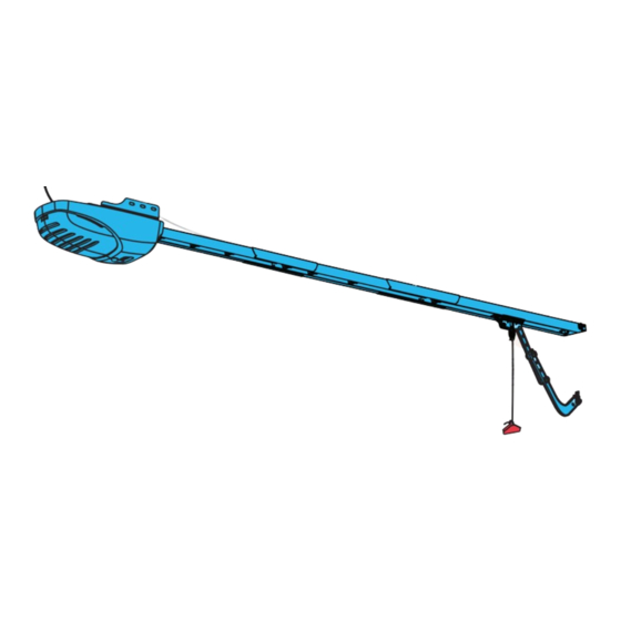
Screw Drive Models
A
B
Potential Hazards
Overhead doors are large, heavy objects that move with the help of springs under high tension and electric motors. Since
moving objects, springs under tension, and electric motors can cause injuries, your safety and the safety of others depends
on you reading the information in this installation poster. If you have questions or do not understand the information
presented, call The Genie Company or your local Genie Factory Authorized Dealer. In this section, and those that follow,
the words Danger, Warning and Caution are used to emphasize important safety information.
Danger: indicates an imminently hazardous situation which, if not avoided, will result in death or serious injury.
Warning: indicates a potentially hazardous situation which, if not avoided, could result in death or serious injury.
Caution: indicates a potentially hazardous situation which, if not avoided, may result in injury or property damage.
Note is used to indicate important steps to be followed or important considerations.
Pre-Installation Considerations
This opener includes parts and supplies needed for installation in MOST garages and on MOST garage doors. There are
many variations of garages and garage doors. A few additional parts and supplies may be needed for installation in YOUR
garage and to YOUR garage door. While going over these instructions, please note the additional items you may need.
For help finding a local Genie® Professional Dealer, call 1-800-OK-GENIE or Customer Service at 1-800-35-GEN E.
There are a few specific areas of interest which might require extra materials. They are: 1) The header above the garage
door where torsion springs are used–does it extend far enough above the spring(s) to allow mounting of the header
bracket. If not, or if you can't tell–you will probably need a piece of 2" x 6" lumber to span across wall studs. 2) The area
overhead where the powerhead will be mounted–if you have a finished ceiling, you will need a piece of angle iron which
can span across beams of trusses. 3) Is there wood along the door tracks near the floor where the Safe-T-Beam® can be
most easily mounted, or will you need fasteners for mounting to the track itself or some other material? 4) Measure the
height of your door. If it is taller than 7', you will need a Rail Extension Kit.
Will you need extension brackets or wooden blocks to extend the Safe-T-Beam far enough off the wall to see past any door
hardware?
Is there an electrical outlet within approximately 3' of the point where the powerhead will be? If not, you need to contact a
licensed electrician.
Check condition of the door and all its associated hardware: Tracks, springs, hinges, rollers. Is anything loose or appear
worn? If so, call a trained professional for an evaluation and repairs, if needed. DO NOT ATTEMPT TO ADJUST SPR NGS OR
THE R ATTACHED PARTS!
Operate the door manually. Does it move freely and smoothly? Check the balance of the door by lifting it by hand
approximately halfway open and let go. It should stay put or move very slowly. If not, call a trained professional for repairs.
Remove all ropes and remove or disable all locks connected to the garage door. It is also recommended that T-handles be
removed. Closed loop lifting handles with no protruding parts can remain.
ASSEMBLY/INSTALLATION
POSTER
C
IMPORTANT INSTALLATION INSTRUCTIONS
TO REDUCE THE RISK OF SEVERE INJURY OR DEATH
READ AND FOLLOW ALL SAFETY, INSTALLATION AND OPERATION INSTRUCTIONS. If you have
any questions or do not understand an instruction, call The Genie® Company or your local
Genie® Factory Authorized Dealer.
• DO NOT install operator on an improperly balanced door. An improperly balanced door
could cause severe injury. Repairs and adjustments to cables, spring assembly, and other
hardware must be made by a trained service person using proper tools and instructions.
• Remove all ropes, and disable all locks connected to the door before installing operator.
• Install door oper
a
accidental release.
• DO NOT connect the operator to the source of power until instructed to do so.
•
L
c o
t a
t e
e h
w
a
c l l
n o
o s
e l
b
t u
o t
so small children cannot reach it. C) Away from all moving parts of the door.
• Install the entrapment WARNING label next to the wall button or console, in a prominent
location. Install the emergency release tag on, or next to, the emergency release handle.
• The opera
at the center of the doorway.
A moving door could result in serious injury or death.
• Keep people clear of opening while door is moving.
• DO NOT
allow children to play with the door operator.
• DO NOT
operate a door that jams or one that has a broken spring.
An Electrical Shock could result in serious injury or death.
• Turn off power before removing operator cover.
• When replacing cover, make sure wires are not pinched or near moving parts.
• Operator must be properly grounded.
WARNING–HIGH SPRING TENSION
• DO NOT try to remove, repair or adjust springs or anything to which door
spring parts are fastened, such as wood block, steel brackets, cables or other
like items.
• Repairs and adjustments must be made by a trained door system technician
using proper tools and instructions
Need help or have questions? DO NOT RETURN to the store.
800-354-3643
Call us:
1
W A R N I N G
. r
M
o
n u
t t
e h
e
m
e
g r
: n
) A
W
h t i
n i
s
g i
t h
f o
o d
r o
B .
A )
a t
m
n i
m i
W A R N I N G
W A R N I N G
W A R N I N G
.
n e
y c
l e r
a e
e s
w
h t i
n i
u
m
h
i e
h g
o t
5 f
e f
t e
at.
Advertisement

Related Manuals for Genie POSTER


Summary of Contents for Genie POSTER
- Page 1 Screw Drive Models READ AND FOLLOW ALL SAFETY, INSTALLATION AND OPERATION INSTRUCTIONS. If you have any questions or do not understand an instruction, call The Genie® Company or your local Genie® Factory Authorized Dealer. • DO NOT install operator on an improperly balanced door. An improperly balanced door could cause severe injury.
- Page 2 Recommended Tools Parts Included 1/16" 1/8" 9/16" 6' or 7' 1/2" 7/16" 3/8" 1/4" Hardware Bags BLUE BAG Cotter pin (x2) Clevis pin (x2) 3/8"-16 x 7/8" Bolt (x2) Header bracket 1/4"-14 x 3/4" 3/8" Lock nut (x2) Tapered flange screw (x6) Shaft coupler ORANGE BAG Wire clips...
-
Page 3: Rail Assembly
1. Check door height, 8' doors require a Rail Extension Kit (available at leading retail stores) Rail Assembly 2. Fully read instructions and warnings before proceeding (CLEAR BAG hardware) 1a. Slide one rail connector (K) over Powehead end rail section (A) until it locks. 1d. Slide door end rail section (C) into the rail connector until it locks. 1b. Slide middle rail section (B) into the rail connector (K) until it locks. 1f. Secure screw drives of each section with (2) collars and (2) clips. 1c. Slide second rail connector (K) onto other end of middle rail section (B) until it locks. Disengaged Shuttle Engaged Carriage Grooves Door Orientation Toward door Grooves along shuttle fit into rail. Door rail end Clip Collar Slide collar over Slide collar Snap clip Powerhead long hook... - Page 4 Attaching Rail to Powerhead Mount ing R ail Bracket on Header (BLUE BAG hardware) (ORANGE BAG hardware) 2a. Place shaft coupler large hole over 3a. Center header bracket above door, mark holes. Shaft coupler screw drive. 3b. Drill two–5/32" pilot holes in header board or 2" x 6" board connected to wall studs. 2b.
-
Page 5: Mounting Powerhead To Ceiling
Attaching Rail to Bracket Mounting Powerhead to Ceiling (ORANGE BAG hardware) (GREEN BAG hardware) 4a. Elevate opener assembly and position 5a. Find and mark ceiling at center line of door. F door end rail section (C) inside bracket. (not supplied) to joists. Header bracket Cross piece location Door centerline Protective... -
Page 6: Attaching Door Bracket To Door
3/8"-16 x 7/8" braced before mounting door opener. Contact door manufacturer or distributor for any Door bracket Bolt & questions or concerns. The Genie® Company is not responsible for any damage caused 3/8" Lock nut due to an improperly braced door. - Page 7 Installing Safe- T- Beam Installing Wall Console ® (YELLOW BAG hardware) (CLEAR BAG hardware) 8a. P osition Safe- T m a s o r n 9a. Route wire from powerhead to Wall mount To powerhead Sensor each side gar a desired location for wall console 8b. M ark bracket mounting holes and secure with (4) Some homes are pre-wired and ...
-
Page 8: Connecting Power
Light Assembly Connecting Power 10a. Install light bulbs into powehead (F). For Grounded Outlet connection: 11a. Plug in the power cord. Coil excess cord and tape or twist tie it to top of powerhead. (DO NOT PLACE ABOVE LIGHT BULBS.) Each light bulb must be 100 W or less* W A R N I N G Opener is equipped with grounded electrical plug for your protection, and only fits DO NOT alter plug in any way! If you have no grounded ...