Toro TimeCutter Z4220 Operator's Manual
Hide thumbs
Also See for TimeCutter Z4220:
- Operator's manual (44 pages) ,
- Operator's manual (48 pages)
Table of Contents
Advertisement
Advertisement
Table of Contents

Related Manuals for Toro TimeCutter Z4220


Summary of Contents for Toro TimeCutter Z4220
- Page 1 _o_nt on _t. TimeCutte_ Z4200, Z4220, and Z5000 Ridin Mowers Model No. 74360uSerial No. 290000001 and Up Model No. 74363---Serial No. 290000001 and Up Model No. 74370--Serial No. 290000001 and Up G007083 Register at www Toro com, Oriainal instructions I'EN)
- Page 2 You are responsible for operating the product properly and safely. This manual uses two other words to highlight You may contact Toro direcdy at wwwToro.com information, Important calls attention to special product and accessory information, help finding a...
-
Page 3: Table Of Contents
Safety ................Controls Operation......................Think Safety First ............This machine meets or exceeds B71.1-2003 Recommended Gasoline ............specifications of the American National Standards Checldng the Engine Oil Level ......... 16 Institute, in effect at the time of' production. Starting the Engine ..........However, improper or maintenance... - Page 4 A hitch kit is available for this machine and can be ° Remove or mark obstacles such as rocks, tree limbs, obtained by contacting an Authorized Toro Dealer. etc. from the mowing area Tall grass can hide obstacles. Do not tow without first installing this manufacn.n:er...
- Page 5 Toro Riding Mower Safety Never fill containers inside a vehicle or on a truck or trailer with a plastic finer.._dways place containers...
- Page 6 Use only Toro approved attachments., Warranty may be voided if used with unapproved attachments, If loading the machine onto a trailer or truck, use a single, flail-width ramp only, The ramp angle should not exceed 15 degrees Note: Determine the left and right sides of the...
- Page 7 Example: Compare slope with folded ed,...
-
Page 8: Removing The Mower
Safety and Bnstructional Decals Safer T decals and insrxuctions are easily visible to the operator and are located near any area of potential danger, Replace any decal that is damaged or lost. I14-1606 Entanglement hazard, belt--keep all guards in place 93-7009 Warning--don't operate the mower with the deflector up or... - Page 9 112-9750 110.6691 Neutral Parking position Reverse Thrown object hazard--keep bystanders a safe distance Fast from the machine Slow Thrown object hazard, mower--do not operate the without deflector, discharge cover or grass collection system in place Cuttingtdismemberment of hand or foot--stay away from moving parts 112-9751 Neutral...
- Page 10 A@ @A 114-8532 Battery Symbols Bypass lever position for 2,, Bypass lever position for operating the machine pushing the machine are on your battery Some or all of these symbols Explosion hazard Keep bystanders a safe distance from the battery 2,, No fire, open flame, or Wear eye protection;...
- Page 11 115-2450 Half Empty Full '1. Fuelgauge 115-2489 Hatf Empty Full 1,, Fuelgauge 115-2451 Full Half Empty Fuelgauge...
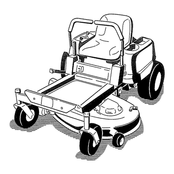
- Page 12 Product Overview GOD7291 Figure 3 Rear drive wheel Anti-scalp roller 1, Footrest Contm! panel Front caster wheel Motion control levers Washout fitting Height of cut lever Mower deck Operator seat Fuel gauge Figure 4 5o Deflector t., Motion control levers Gas tank cap Engine guard (Model 74370 only) Engine...
- Page 13 Controls reverse; wheel speed is proportional to the amount the lever is moved, Move the control levers outward from Become familiar with all of the controls in Figure 3, the center to the park position and exit the machine Figure 4, and Figure 5 before you start the engine and (Figure i5) Always position the motion...
-
Page 14: Controls
Operation Note: Detern_ne the left and fight sides of _he machine from d_enormal operating position.. Think Safety First Please carefi_y read a_ of the safety instructions decals in dae safety section,, Knowing this information could help you, your family, pets or bystanders avoid injinx, GOQDS_3... - Page 15 In certain conditions during fueling, static In certain conditions, gasoline is extremely electricity be released causing a spark flammable and highly explosive. A fire or which ignite the gasoline vapors. A fire explosion from gasoline can burn you and others and can damage property.
-
Page 16: Checldng The Engine Oil Level
Add thecorrect a mountof gasstabilizer/conditioner allows gasoline to expand Do not fi!! the fuel tank completely flail. to the gas Install the fuel tank cap securely Wipe up any Note: A furl stabilizer/conditioner is most effective gasoline that may have spilled.. when mixed with fresh gasoline. - Page 17 Move the throtde lever to Choke before starting a cold eng_e (Figure 11) Note: A warm or hot engine may not require choking_ G005058 Figure Control panel Ignition key--run position ignition key--start position Start After the engine starts, move the throttle lever to Fast _igure 11)..
-
Page 18: Stopping The Engine
The Safety interlock System If safety interlock switches are disconnected or damaged the machine could operate unexpectedly causing personal injury. • Do not tamper with the interlock switches. Check the operation of the interlock switches daily and replace any damaged switches before operating... - Page 19 Driving Forward or Backward The throrde control regulates the engine speed as measured in rpm (revolutions per minute),. Place the throttle control in the Fast position for best performance° Always operate in the frill throttle position, machine can spin very rapidl3: operator may lose control of the machine...
-
Page 20: Stopping The Machine
Positioning the Seat To turn, release the pressure on the motion control lever towed the direction you want to turn, The seat can move forward and back-ward Position To stop, push the motion control levers to neutral, seat where you have the best control of the machine and are most comfortable. -
Page 21: Pushing The Machine
Move file bypass levers rearward and tllen down to lock them in place as shown in Figure 21 to disengage the wheel motors Repeat this on each side of the machine 5, Move the motion control levers inward to tile neutral position The machine is now able to be pushed by hand.. -
Page 22: Grass Deflector
Grass Deflector Mowing Direction Alternate mowing direction to keep the grass standing The mower has a hinged grass deflector that disperses straight. This also helps disperse c_ppings which clippings to the side and down toward the au-f. enhances decomposition and fer_ation.. Mow at Correct Intervals Without the grass... - Page 23 Check the cutter blades da_ilyfor sharpness, and for any wear or damage,, File down any nicks and sharpen the blades as necessary, a blade is damaged or worn, replace it immediately with a genuine Toro replacement blade_...
-
Page 24: Maintenance
Maintenance Note: Determine the left and right sides of the machine from the normal operating position, Recommended Maintenance Schedule(s) Maintenance Service Maintenance Procedure Interval . Check the safety interlock system. • Check the air cleaner for dirty, loose or damaged parts., •... -
Page 25: Premaintenance Procedures
Lubrication Premaintenance Procedures Greasing the Bearings Raising the Seat Service Interval: E.very 25 hours--Grease lubrication points Make sure the motion control levers are locked in the Grease Type: 2 General Purpose Lithium Base park position. Lift the seat fore,yard. Grease The following components can be accessed by raising I.. -
Page 26: Engine Maintenance
Engine Maintenance Connect a grease gun to eac!_ fitting (Figure 2.3 and Figure 24).. Pump grease into the fittings until grease begins to ooze out of the bearings Servicing the Air CJeaner 5. Wipe up any excess grease. Service Interval: Before each use or daily---Check air cleaner for dirty, loose or damaged parts. -
Page 27: Servicing The Engine Oil
Replace a dirty., bent, or damaged dement.. Handle new elements carefully; do not use if the rubber seal is damaged.. Clean all air cleaner components of any accumulated dirt or foreign material.. Prevent any dirt from entering the carburetor.. 5.. Install the ak cleaner dement with the pleated side "out"... - Page 28 2. Park the machine so that the &ain side is slightly lower than the opposite side to assure the oil drains completely. Disengage the blade control switch _Lndmove the motion controls outward to the park position 4. Stop the engine, remove the key, and wait for all moving parts to stop before leaving the operating position.
-
Page 29: Servicing The Spark Plug
G005D70 GD05177 Figure 30 Figure 31 Oil filter Adapter 1,, Spark plug and wire location Gasket 15. Slowly pour appro>imately 80% of the specified Checking the Spark Plug into the filler robe (Figure 27)_ 1.. Look at the center of the spark plug (Figure 32),. 16. -
Page 30: Fuel System Maintenance
Fuel System Annually or every 100 hours of operation (more often under extremely dust-}; dirt 3, conditions), remove the Maintenance blower housing and any other cooling shrouds: Clean the cooling fins and external surfaces as necessary Make sure the cooling shrouds are reinstalled. -
Page 31: Charging The Battery
Electrical System Maintenance CALIFORNIA Proposition 65 Warning Battery posts, terminals, related accessories contain lead lead compounds, chemicals known to the State of California to cause cancer reproductive harm. G00507_ Wash hands after handling. Charging the Battery Figure Fuel line from tank Fuel line to engine Removing the Battery... -
Page 32: Servicing The Fuses
Incorrect battery cable routing could damage the machine cables causing sparks. Sparks cause the battery gasses to explode, resulting in personal injury. ° Always disconnect the negative (black) battery cable before disconnecting positive (red) cable. GD00538 Figure 35 Always connect the positive (red) battery... -
Page 33: Drive System Maintenance
Drive System Maintenance Checking the Tire Pressure Service Interval: Every 25 hours--Check tire pressure., GDt35073 Maintain the air pressure in the front and rear tires as specified, Uneven tire pressm'e can cause uneven cut,, Check the pressure at the valve stem (Figure 37), Check the tires when they are cold to get the most accurate pressure reading,... -
Page 34: Mower Maintenance
Mower Maintenance Servicing the Cutting BRades Maintain sharp blades throughout the cutting season because sharp blades cut cleanly without tearing or shredding the grass blades. Tearing and shredding turns G005530 grass brown at the edges, which slows growth Figure 38 increases the chance of disease. - Page 35 1/8 inch (3rm-n), the blade spindle could be bent. Contact an Audaorized Toro Dealer for service. Measure from the tip of the blade to the flat surface If the variance is within constraints, move to the here, The variance should be no more than 1/8 inch...
- Page 36 LeveBing the Mower Deck Check to ensure the mower deck is level any time you instal1 the mower or when you see an uneven cut on your lawn, The mower deck must be ched_ed for bent blades prior to leveling; any bent blades must be removed and replaced, Refer to the Cheddng for Bent Blades...
- Page 37 4QF v Figure 47 Mower Decks with 3 Blades Blades side to side Outside cutting edges Sail area of blade Measure from the tip of the blade to the flat surface here Measure between the outside cutting edges and the flat surface (Figure 46 and Figure 47)4 If both Figure measurements axe not within 3/16 inch (5 mm), an...
- Page 38 Figure 49 Mower Decks with 2 Blades 1, Blades front to rear Measure from the tip of the blade to the flat surface here G005075 Figure 51 Locknut 1o Adjusting rod 2,, Adjusting block 7. To rise the front of the mower, tighten the adjustment nut.
-
Page 39: Mower Belt Maintenance
Mower BeR Maintenance Inspecting the Belts Service Interval: Every 25 hours---Check the belts for wear/cracks Check the belts for cracks, frayed edges, burn marks, or •"myother damage Replace damaged belts Replacing the Mower Belt Squealing when the belt is rotating, blades slipping when cutting grass, frayed belt edges, burn marks, and crad_s ,xre signs of a worn mower belt Replace the mower belt... -
Page 40: Installing The Mower
wait for all moxdng parts to stop before leaving the operating position Slide the mower under the machine Lower the height-of-cut lever to the lowest position., Lift the rear of the mower de& and guide the hanger brackets over the rear lift rod (Figure 53) Attach the front support rod to the mower deck with the clevis pin and hairpin... -
Page 41: Of The Mower
Cleaning Washing the Underside of the Mower Service Interval: Before each use or daily--Clean mower housing _Tash the underside of the mower after each use to prevent grass buildup for Janproved mulch action and clipping dispersal, 1,. Park the machine on a level surface and disengage the blade control switch... -
Page 42: Cleanlng And Storage
Storage Note: If the mower is not clean after one washing, soak it and let it stand for .30 minutes Then repeat the process.. Cleaning and Storage Run the mower again for one to three minutes Disengage the blade control switch, move the remove excess water. - Page 43 Important: Do not store stabilizer/conditioned gasoline over 30 days. 1 I. Remaove the spark plug(s) and ched_ its condition; refer to Servidng the Spark Plug in the Engine Maintenance secdon With the spark plug(s) removed from the engine, pour two tablespoons engine oil into the spark plug hole..
- Page 44 Troubmeshooting Corrective Action Problem Possible Cause Reduce ground speed The engine overheats. The engine toad is excessive, Add oil to the crankcase The oil level in the crankcase is low Remove the obstruction from the The cooling fins and air passages cooling fins and air passages.
- Page 45 Corrective Action Problem Possible Cause 1. The engine mounting bolts are loose There is abnormal vibration., Tighten the engine mounting bolts 2, The engine pulley, idler pulley, or blade 2. Tighten the appropriate pulley pulley isloose, Contact an Authodzed Service Dealer. The engine pulley is damaged, The cutting blade(s) is/are bent or install a new cutting blade(s)
- Page 47 Notes:...