Table of Contents
Advertisement
Form No. 3363-768 Rev A
TimeCutter™ Z4235 and Z5035
Riding Mower
Model No. 74365—Serial No. 310000001 and Up
Model No. 74366—Serial No. 310000001 and Up
Model No. 74376—Serial No. 310000001 and Up
To register your product or download an Operator's Manual or Parts Catalog at no charge, go to www.Toro.com.
Original Instructions (EN)
Advertisement
Table of Contents

Related Manuals for Toro TimeCutter Z4235


Summary of Contents for Toro TimeCutter Z4235
- Page 1 Model No. 74365—Serial No. 310000001 and Up Model No. 74366—Serial No. 310000001 and Up Model No. 74376—Serial No. 310000001 and Up To register your product or download an Operator's Manual or Parts Catalog at no charge, go to www.Toro.com. Original Instructions (EN)
-
Page 2: Introduction
Authorized Service applications. It is primarily designed for cutting grass Dealer or Toro Customer Service and have the model on well-maintained lawns. It is not designed for cutting and serial numbers of your product ready. Figure 1... -
Page 3: Table Of Contents
Safety ................4 Schematics ..............45 Safe Operating Practices ........4 Conditions and Products Covered under The Toro Riding Mower Safety ........6 Toro Total Coverage Guarantee ...... 48 Slope Indicator............. 7 Limited Warranty for Commercial Use ....48 Safety and Instructional Decals ......8 Owner Responsibilities........ -
Page 4: Safety
Safety • Never leave a running machine unattended. Always turn off blades, set parking brake, stop engine, and remove key before dismounting. This machine meets or exceeds the B71.1-2003 specifications of the American National Standards • Turn off blades when not mowing. Stop the engine Institute, in effect at the time of production. - Page 5 Tall grass can hide A hitch kit is available for this machine and can be obstacles. obtained by contacting an Authorized Toro Dealer. • Avoid sudden starts when mowing uphill because Do not tow without first installing this manufacturer the mower may tip backwards.
-
Page 6: Toro Riding Mower Safety
• Maintain or replace safety and instruction decals as necessary. • Use only genuine Toro replacement parts to ensure that original standards are maintained. Toro Riding Mower Safety The following list contains safety information specific to Toro products or other safety information that you must know that is not included in the ANSI standards. -
Page 7: Slope Indicator
Slope Indicator G011841 Figure 3 This page may be copied for personal use. 1. The maximum slope you can safely operate the machine on is 15 degrees. Use the slope chart to determine the degree of slope of hills before operating. Do not operate this machine on a slope greater than 15 degrees. Fold along the appropriate line to match the recommended slope. -
Page 8: Safety And Instructional Decals
Safety and Instructional Decals Safety decals and instructions are easily visible to the operator and are located near any area of potential danger. Replace any decal that is damaged or lost. 114-1606 1. Entanglement hazard, belt—keep all guards in place. 93-7009 1. - Page 9 112-9750 110-6691 1. Parking position 4. Neutral 1. Thrown object hazard—keep bystanders a safe distance 2. Fast 5. Reverse from the machine. 3. Slow 2. Thrown object hazard, mower—do not operate the without deflector, discharge cover or grass collection system in place.
- Page 10 114-8532 1. Bypass lever position for 2. Bypass lever position for Battery Symbols operating the machine pushing the machine Some or all of these symbols are on your battery 1. Explosion hazard 6. Keep bystanders a safe distance from the battery. 2.
- Page 11 117-7221 1. Fuel 2. Full 3. Half 4. Empty 117-7222 1. Fuel 2. Full 3. Half 4. Empty...
-
Page 12: Product Overview
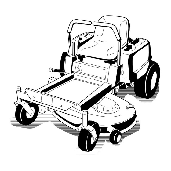
Product Overview Figure 4 1. Footrest 4. Control panel 7. Rear drive wheel 10. Anti-scalp roller 2. Height of cut lever 5. Motion control levers 8. Washout fitting 11. Front caster wheel 3. Fuel gauge 6. Operator seat 9. Mower deck G005180 Figure 5 1. -
Page 13: Controls
Controls Blade Control Switch (Power Take-Off) The blade control switch, represented by a power Become familiar with all of the controls in Figure 4, take-off (PTO) symbol, engages and disengages power Figure 5, and Figure 6 before you start the engine and to the mower blades (Figure 6). -
Page 14: Operation
Operation Note: Determine the left and right sides of the machine from the normal operating position. Think Safety First Please carefully read all of the safety instructions and decals in the safety section. Knowing this information could help you, your family, pets or bystanders avoid injury. -
Page 15: Fuel Gauge
DANGER WARNING In certain conditions, gasoline is extremely Gasoline is harmful or fatal if swallowed. flammable and highly explosive. A fire or explosion Long-term exposure to vapors can cause serious from gasoline can burn you and others and can injury and illness. damage property. -
Page 16: Checking The Engine Oil Level
Checking the Engine Oil Level Before you start the engine and use the machine, check the oil level in the engine crankcase; refer to Checking the Oil Level in the Engine Maintenance section. Starting and Stopping the Engine Starting the Engine 1. -
Page 17: Operating The Blades
G005183 G005184 Figure 13 1. Control panel 5. Run 2. Ignition key—run position 6. Start 3. Ignition key—start position 7. Choke control 4. Off Figure 12 1. Control panel 4. Continuous variable 5. After the engine starts, push down on the Choke setting control (Figure 13). -
Page 18: Stopping The Engine
The Safety Interlock System WARNING If safety interlock switches are disconnected or damaged the machine could operate unexpectedly causing personal injury. • Do not tamper with the interlock switches. • Check the operation of the interlock switches G005185 daily and replace any damaged switches before operating the machine. -
Page 19: Driving Forward Or Backward
Driving Forward or Backward The throttle control regulates the engine speed as measured in rpm (revolutions per minute). Place the throttle control in the Fast position for best performance. Always operate in the full throttle position. WARNING The machine can spin very rapidly. The operator may lose control of the machine and cause personal injury or damage to the machine. -
Page 20: Stopping The Machine
To turn, release the pressure on the motion control 1. Raise the seat and loosen the adjustment knob just lever toward the direction you want to turn. enough that seat can move (Figure 20). To stop, push the motion control levers to neutral. Stopping the Machine To stop the machine, move the motion control levers to neutral and outward to the park position, disengage the... -
Page 21: Pushing The Machine By Hand
4. Move the bypass levers rearward and then down to lock them in place as shown in Figure 22 to disengage the wheel motors. Repeat this on each side of the machine. 5. Move the motion control levers inward to the neutral position. -
Page 22: Grass Deflector
Grass Deflector Mowing Direction Alternate mowing direction to keep the grass standing The mower has a hinged grass deflector that disperses straight. This also helps disperse clippings which clippings to the side and down toward the turf. enhances decomposition and fertilization. DANGER Mow at Correct Intervals Without the grass deflector, discharge cover, or... - Page 23 File down any nicks and sharpen the blades as necessary. If a blade is damaged or worn, replace it immediately with a genuine Toro replacement blade.
-
Page 24: Maintenance
Maintenance Note: Determine the left and right sides of the machine from the normal operating position. Recommended Maintenance Schedule(s) Maintenance Service Maintenance Procedure Interval • Change the engine oil. After the first 8 hours • Check the safety interlock system. •... -
Page 25: Premaintenance Procedures
Premaintenance Lubrication Procedures Greasing the Bearings Raising the Seat Service Interval: Every 25 hours—Grease all lubrication points. Make sure the motion control levers are locked in the Grease Type: No. 2 General Purpose Lithium Base park position. Lift the seat forward. Grease The following components can be accessed by raising 1. -
Page 26: Engine Maintenance
Engine Maintenance 4. Connect a grease gun to each fitting (Figure 24 and Figure 25). Pump grease into the fittings until grease begins to ooze out of the bearings. Servicing the Air Cleaner 5. Wipe up any excess grease. Note: Service the air cleaner more frequently (every few hours) if operating conditions are extremely dusty or sandy. -
Page 27: Servicing The Engine Oil
Checking the Engine Oil Level Every 100 hours—Service the paper element. (more often in dusty, dirty Service Interval: Before each use or daily conditions) Note: Check the oil when the engine is cold. Every 200 hours/Yearly (whichever comes first)—Replace the paper WARNING element. -
Page 28: Changing The Engine Oil
3. Disengage the PTO, move the motion control levers to the neutral locked position and set the parking brake. 4. Stop the engine, remove the key, and wait for all G012157 moving parts to stop before leaving the operating position (Figure 29). G012157 G012153 Figure 29... -
Page 29: Servicing The Spark Plug
5. Slowly pour approximately 80% of the specified oil into the filler tube and slowly add the additional oil to bring it to the Full mark (Figure 30). G012157 G008796 Figure 30 Changing the Engine Oil Filter Service Interval: Every 200 hours—Change the oil G008748 filter. -
Page 30: Cleaning The Cooling System
Removing the Spark Plug Installing the Spark Plug 1. Disengage the PTO, move the motion control levers Tighten the spark plug(s) to 16 ft-lb (22 N-m). to the neutral locked position and set the parking brake. 2. Stop the engine, remove the key, and wait for all moving parts to stop before leaving the operating position. -
Page 31: Fuel System Maintenance
Fuel System Maintenance DANGER In certain conditions, gasoline is extremely flammable and highly explosive. A fire or explosion from gasoline can burn you and others and can damage property. • Perform any fuel related maintenance when the engine is cold. Do this outdoors in an open area. Wipe up any gasoline that spills. -
Page 32: Electrical System Maintenance
Electrical System WARNING Maintenance Incorrect battery cable routing could damage the machine and cables causing sparks. Sparks can cause the battery gasses to explode, WARNING resulting in personal injury. • Always disconnect the negative (black) CALIFORNIA battery cable before disconnecting the Proposition 65 Warning positive (red) cable. -
Page 33: Servicing The Fuses
Figure 37 1. Positive battery post 3. Red (+) charger lead g012173 2. Negative battery post 4. Black (-) charger lead Figure 38 1. Main-30 amp 2. Charge circuit-25 amp Note: Do not run the machine with the battery disconnected, electrical damage may occur. 4. -
Page 34: Drive System Maintenance
File down any nicks and sharpen the pressure reading. blades as necessary. If a blade is damaged or worn, replace it immediately with a genuine Toro replacement Tire Pressures blade. For convenient sharpening and replacement, you may want to keep extra blades on hand. - Page 35 3. Measure from the tip of the blade to the flat surface here. Figure 40 1. Cutting edge 3. Wear/slot forming G009680 2. Curved area 4. Damage Figure 42 Checking for Bent Blades 1. Blade, in position for measuring 2. Level surface Note: The machine must be on a level surface for the 3.
-
Page 36: Removing The Blades
Installing the Blades To ensure optimum performance and continued 1. Install the blade onto the spindle shaft (Figure 45). safety conformance of the machine, use genuine Toro replacement blades. Replacement blades made by other Important: The curved part of the blade must... -
Page 37: Leveling The Mower Deck
Leveling the Mower Deck G005278 Check to ensure the mower deck is level any time you install the mower or when you see an uneven cut on your lawn. The mower deck must be checked for bent blades prior to leveling; any bent blades must be removed and replaced. - Page 38 Figure 51 Mower Decks with 2 Blades 1. Blades front to rear 2. Measure from the tip of the blade to the flat surface here G009659 Figure 52 G005074 Mower Decks with 3 Blades 1. Blades front to rear 3. Measure from the tip of the blade to the flat surface here 2.
-
Page 39: Removing The Mower
7. To raise the front of the mower, tighten the adjustment nut. To lower the front of the mower, loosen the adjustment nut. 8. After adjustment, check the front-to-rear slope again. Continue adjusting the nut until the front blade tip is 1/16-5/16 inch (1.6-7.9 mm) lower than the rear blade tip (Figure 51 and Figure 52). -
Page 40: Replacing The Grass Deflector
3. Slide the mower under the machine. 4. Replace the grass deflector (Figure 56). 4. Lower the height-of-cut lever to the lowest position. 5. Slide rod, straight end, through the rear grass deflector bracket. 5. Lift the rear of the mower deck and guide the hanger brackets over the rear lift rod (Figure 55). -
Page 41: Cleaning
Cleaning Note: If the mower is not clean after one washing, soak it and let it stand for 30 minutes. Then repeat the process. Washing the Underside of the 8. Run the mower again for one to three minutes to Mower remove excess water. -
Page 42: Storage
Storage Important: Do not store stabilizer/conditioned gasoline over 30 days. Cleaning and Storage 11. Remove the spark plug(s) and check its condition; refer to Servicing the Spark Plug in the Engine 1. Disengage the blade control switch, move the Maintenance section. With the spark plug(s) motion controls outward to the park position, stop removed from the engine, pour two tablespoons of the engine, and remove the key. -
Page 43: Troubleshooting
Troubleshooting Problem Possible Cause Corrective Action The engine overheats. 1. The engine load is excessive. 1. Reduce ground speed. 2. The oil level in the crankcase is low. 2. Add oil to the crankcase. 3. The cooling fins and air passages 3. - Page 44 Problem Possible Cause Corrective Action There is abnormal vibration. 1. The engine mounting bolts are loose. 1. Tighten the engine mounting bolts. 2. The engine pulley, idler pulley, or blade 2. Tighten the appropriate pulley. pulley is loose. 3. The engine pulley is damaged. 3.
-
Page 45: Schematics
Schematics G009744 Electrical Diagram (Rev. A) - Page 46 Notes:...
- Page 47 Notes:...
-
Page 48: Conditions And Products Covered Under The Toro Total Coverage Guarantee
Countries Other than the United States or Canada Customers who have purchased Toro products exported from the United States or Canada should contact their Toro Distributor (Dealer) to obtain guarantee policies for your country, province, or state. If for any reason you are dissatisfied with your Distributor’s service or have difficulty obtaining guarantee information, contact the Toro importer.