Toro TimeCutter Z5000 Operator's Manual
Hide thumbs
Also See for TimeCutter Z5000:
- Operator's manual (44 pages) ,
- Operator's manual (47 pages) ,
- Operator's manual (48 pages)

Related Manuals for Toro TimeCutter Z5000


Summary of Contents for Toro TimeCutter Z5000
- Page 1 Form No. 3358-922 Rev A Count on it. mmmm TimeCutter_ Z5000 Riding Mower Model No. 74370--Serial No. 280000001 and Up G007290 Register at w_v.Toro.com. Original Instructions (EN)
- Page 2 Whenever you need service, genuine Toro parts, or additional information, contact an Authorized Service Contents Dealer or Toro Customer Service and have the model and serial numbers of your product read> Figure 1 Introduction ..............identifies the location of the model and serial numbers Safe_ _................
- Page 3 Controls ............. Safety Operation ..............Think Safety First ..........This machine meets or exceeds the B71.1-2003 Recommended Gasoline ........specifications of the American National Standards Chec_ng the Engine Oil Level ......Institute, in effect at the time of production. Starting the Engine ..........However, improper use or maintenance...
- Page 4 A hitch _t is available for this machine and can be • Remove or mark obstacles such as rocks, tree limbs, etc. from the mowing area. Tall grass can hide obtained by contacting an Authorized Toro Dealer. obstacles. Do not tow without first installing this manufacturer...
-
Page 5: Toro Riding Mower Safety
ARvays place containers on The following list contains safety information specific to the ground away from your vehicle before filling. Toro products or other safety information that you must M_ow that is not included in the ANSI standards. Remove gas-powered... - Page 6 Use only Toro approved attachments. Warranff be voided if used with unapproved attachments. If loading the machine onto a trailer or truck, use a single, fL_-width ramp only. The ramp angle should not exceed 15 degrees. Note: Determine the left and right sides of the...
- Page 7 This is a 5° slope No Slope Example: Compare slope with folded ©...
- Page 8 Safety and Instructional Decals Safeb7 decals and instructions are easily visible to the operator and are located near any area of potential danger. Replace any decal that is damaged or lost. 114-1606 Entanglement hazard, belt--keep all guards in place. 106-8717 Read the instructions before servicing or performing maintenance.
- Page 9 N(¢) 112-9751 Neutral Parking position Fast Reverse Stow 112-9802 Height-of-cut 112-9840 Read the Operator's Remove the ignition key Manual. and read the instructions before servicing or performing maintenance. Height of cut 115-2500 Choke Power take-off (PTO), Blade control switch on some models Fast Blade control switch--Off...
- Page 10 Battery Symbols Some or all of these symbols are on your battery Explosion hazard Keep bystanders a safe distance from the battery. No fire, open flame, or Wear eye protection; smoking. explosive gases can cause blindness and other injuries Caustic liquid/chemical Battery acid can cause burn hazard blindness or severe burns.
-
Page 11: Product Overview
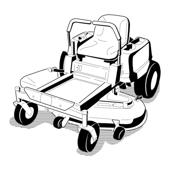
Product Overview G007291 Figure Footrest Rear drive wheel Control panel Anti-scalp roller Motion control levers Front caster wheel Height of cut lever Washout fitting Mower deck Fuel gauge Operator seat .3005180 Figure Motion control levers Deflector Gas tank cap Height of cut lever Engine Engine guard... -
Page 12: Controls
Controls reverse; wheel speed is proportional to the amount the lever is moved. Move the control levers outward from Become familiar vdth all of the controls in Figure 3, the center to the park position and exit the machine Figure 4, and Figure 5 before you start the engine and (Figure 15). -
Page 13: Operation
Operation Note: Determine the left and right sides of the machine from the normal operating position. Think Safety First Please carefully read all of the safe b- instructions decals in the safe b- section. Knowing this information could help you, your famil3; pets or bystanders avoid injur3= G0005t3... - Page 14 In certain conditions, gasoline is extremely In certain conditions during fueling, static flammable and highly explosive. A fire or electricity be released causing a spark explosion from gasoline can burn which can ignite the gasoline vapors. A fire others and can damage property.
-
Page 15: Starting The Engine
Add the correct amount of gas stabilizer/conditioner tank (Figure 9). This space in the neck of the tank to the gas. allows gasoline to expand. Do not fill the fuel tank completely full. Note: A fuel stabilizer/conditioner is most effective Install the fuel tank cap securel>... -
Page 16: Operating The Blades
between attempts. Failure to follow these instructions can damage the starter motor. G005056 Figure 10 Blade control switch--Off Control panel position G005058 Move the throttle lever to Choke before starting a cold engine (Figure 11). Figure Control panel Note: A warm or hot engine may not require Ignition key--run position choMng. -
Page 17: Stopping The Engine
The Safety Interlock System If safety interlock switches are disconnected or damaged the machine could operate unexpectedly causing personal injury. • Do not tamper with the interlock switches. G005059 • Check the operation of the interlock switches daily and replace any damaged switches before... -
Page 18: Driving Forward Or Backward
Driving Forward or Backward To turn, release pressure on the motion control lever toward the direction you want to turn (Figure 15). The throttle control regulates the engine speed The farther you move the motion control levers in measured in rpm (revolutions per minute). -
Page 19: Positioning The Seat
Adjusting the Motion Control Levers 4.5 in (115 mm) Adjusting the Height 4 in (102 mm) The motion control levers can be adjusted higher or 3.5 in (89 mm) lower for maximum operator comfort. 3 in (76 mm) 1. Remove the 2 bolts holding the control lever to the... -
Page 20: Side Discharge
To Push the Machine 1. Park the machine on a level surface and disengage the blade control svdtch. Without the grass deflector, discharge cover, or complete grass catcher assembly mounted Move the motion control levers outward to park in place, you and others are exposed to blade... - Page 21 If enhances decomposition and fertilization. a blade is damaged or worn, replace it immediately with a genuine Toro replacement blade. Mow at Correct Intervals Normal13, mow every four days. But remember, grass grows at different rates at different times.
-
Page 22: Maintenance
Maintenance Note: Determine the left and right sides of the m;_chine from the norm;_l operating position. Recommended Maintenance Schedule(s) Maintenance Service Maintenance Procedure Interval • Check the safety interlock system. • Check the air cleaner for dirty, loose or damaged parts. •... -
Page 23: Premaintenance Procedures
Lubrication Premaintenance Procedures Greasing the Bearings Raising the Seat Service Interval: Every 25 hours--Grease lubrication points. Make sure the motion control levers are locked in the Grease Type: No. 2 General Purpose Lithium Base park position. Lift the seat forward and lower it to the Grease floor board. -
Page 24: Engine Maintenance
Engine Maintenance Connect a grease gun to each fitting (Figure 21 and Figure 22). Pump grease into the fittings until grease begins to ooze out of the bearings. Servicing the Air Cleaner 5. Wipe up any excess grease. Service Interval: Before each use or dail3_Check air cleaner for dirb, loose or damaged parts. -
Page 25: Servicing The Engine Oil
Replace a dirt), bent, or damaged element. Handle new elements carefully; do not use if the rubber seal is damaged. Clean all air cleaner components of any accumulated dirt or foreign material. Prevent any dirt from entering the carburetor. Install the air cleaner element with the pleated... - Page 26 Park the machine so that the drain side is slightly lower than the opposite side to assure the oil drains completel> Disengage the blade control switch and move the motion controls outward to the park position. Stop the engine, remove the ke), and wait for all moving parts to stop before leaving the operating position.
-
Page 27: Servicing The Spark Plug
G005177 G005070 Figure 28 Figure 29 Oil filter 3. Adapter 1. Spark plug and wire location Gasket 15. Slowly pour approximately 80% of the specified Checking the Spark Plug into the filler tube (Figure 25). 1. Look at the center of the spark plug (Figure 30). 16. -
Page 28: Fuel System Maintenance
Annuallyor every100hoursof operation{moreoften Fuel System underextremely dus_% dirty conditions), r emove the Maintenance blowerhousingandanyothercoolingshrouds. C lean the coolingfins andexternal s urfaces a snecessar): Make surethe coolingshrouds arereinstalled. T orquethe blowerhousingscrews to 5.5ft-lb (7.5N-m). In certain conditions, gasoline is extremely Important: Operating the engine with... -
Page 29: Charging The Battery
Electrical System Maintenance CALIFORNIA Proposition 65 Warning Battery posts, terminals, and related accessories contain lead and lead compounds, chemicals known to the State of California to cause cancer reproductive harm. G005071 Wash hands after handling. Charging the Battery Figure Fuel line from tank Fuel line to engine Removing the Battery... -
Page 30: Servicing The Fuses
Incorrect battery cable routing could damage the machine and cables causing sparks. Sparks cause the battery gasses to explode, resulting in personal injury. • Always disconnect the negative (black) battery cable before disconnecting positive (red) cable. G000538 Figure 33 • Always connect the positive... -
Page 31: Checking Tire Pressure
Drive System Maintenance Checking the Tire Pressure Service Interval: Every 25 hours--Check tire pressure. G005073 Maintain the air pressure in the front and rear tires as specified. Uneven tire pressure can cause uneven cut. Check the pressure at the wflve stem (Figure 35). Check the tires when they are cold to get the most accurate pressure reading. -
Page 32: Mower Maintenance
File down any nicks and sharpen the Checking for Bent Blades blades as necessar 7 If a blade is damaged or worn, replace it immediately vdth a genuine Toro replacement 1. Raise the height-of-cut lever to the transport blade. -
Page 33: Leveling The Mower From Side-To-Side
To ensure optimum performance and continued safety conformance of the machine, use genuine Toro G000553 replacement blades. Replacement blades made by other Figure 40 manufacturers may result in non-conformance... -
Page 34: Chec_Ng The Tire Pressure
G005278 Figure 41 Blades side to side Measure here Outside cutting edges Measure between the outside cutting edges G005074 the flat surface (Figure 41). If both measurements are not within 3/16 inch (5 mm), an adjustment required; continue with this procedure. Move the left side of the machine. -
Page 35: Removing The Mower
is 1/16-5/16 inch (1.6-7.9 ram) lower than the rear Measure from the tip of the front blade to the flat blade tip (Figure 43). surface and the tip of the rear blade to the flat surface (Figure 43). If the front blade tip is not 10. -
Page 36: Mower Belt Maintenance
The spring is under tension when installed can cause personal injury. Be careful when removing the belt. G005077 Figure Mower deck Rear lift rod Hanger bracket 'G005191 6. Slide the mower deck rearward to remove the mower Figure 47 belt from the engine puEe> Idler pulley Spring 7. -
Page 37: Replacing The Grass Deflector
Replacing the Grass Deflector Place the spring on the rod, with end wires down, and between the grass deflector brackets. Slide rod Service Interval: Before each use or daily--Inspect through second grass deflector bracket (Figure 48). grass deflector for damage Insert rod at front of grass deflector into short stand-off on deck. -
Page 38: Cleaning
Cleaning Note: If the mower is not clean after one washing, soak it and let it stand for 30 minutes. Then repeat the process. Washing the Underside of the Run the mower again for one three minutes Mower remove excess water. Service Interval: Before each use or daily--Clean mower housing. -
Page 39: Electrical System Maintenance
Storage Important: Do not store stabilizer/conditioned gasoline over 30 days. Cleaning and Storage Remove the spark plug(s) and check condition; refer to Servicing the Spark Plug in Engine 1• Disengage the blade control switch, move the Maintenance , page 24. With the spark plug(s) motion controls outward to the park position, stop removed from the engine, pour two tablespoons the engine, and remove the ke7... -
Page 40: Troubleshooting
Troubleshooting Problem Possible Cause Corrective Action The engine overheats. 1. The engine load is excessive. 1. Reduce ground speed. 2. The oil level in the crankcase is low. 2. Add oil to the crankcase. 3. Remove the obstruction from the 3. - Page 41 Problem Possible Cause Corrective Action There is abnormal vibration. 1. The engine mounting bolts are loose. 1. Tighten the engine mounting bolts. 2. The engine pulley, idler pulley, or blade 2. Tighten the appropriate pulley. pulley is loose. 3. Contact an Authorized Service Dealer. 3.
-
Page 42: Schematics
IGNITION SWITCH IGNITION SW WIRE COLOR CODES ll!ll NO CONNECTION BLACK PINK B I A AND START B I S BROWN BLUE GREEN VIOLET VIEW FROM GREY WHITE BACK OF SW ORANGE YELLOW ENGINE CONNECTIONS SEAT SW I'll PTO SW SHOWN WITH ½... - Page 43 Notes:...
- Page 44 To locate a dealer damages in connection with the use of the Toro Products convenient to you, refer to the Yellow Pages of your covered by this warranty, including any cost or expense telephone directory (look under "Lawn Mowers") or access...
- Page 45 Form No. 3356-530 Rev A Count on it. Cortac_sped con conductor TimeCutter_ Z5000 N° de modelo 74370--N ° de serie 270000001 y superiores G005178 Registre su producto en www.Toro.com. TraducciSn del original (ES)
-
Page 46: Lyndale Avenue South Bloomington, Mn
Servicio T&aico Autorizado o con Asistencia al Cliente Toro, y tenga a mano los nfimeros de modelo y serie de su producto. Figura 1 identifica la ubicacidn de los © 2007--The Toro® Company P6ngase en contacto con nosotros en www.Toro.com. -
Page 47: Table Of Contents
C6mo instalar el cortac&ped ......Seguridad ..............Cambio del deflector de hierba ......PrScticas de operaci6n segura ........ Limpieza ..............Seguridad para cortac&pedes Toro con C6mo lavar los bajos del cortac&ped ....conductor ............Almacenamiento ............Diagrama de pendientes ........ - Page 48 Seguridad EstO alerta, vaya mils despacio y extreme las precauciones en los giros. Mire detrfis y al lado antes de cambiar de direccidn. Esta mfiquina cumple o supera las especificaciones de la norma ANSI B71.1-2003 vigentes en el • No deje nunca desatendida la mfiqulna si estfi...
- Page 49 Antes de ir hacia atrfis o cambiar de sentido, y hacer que la mfiquina patine y clue usted pier& control. mientras lo hace, mire hacia atrfis, hacia abajo y hacia los lados por si hubiera nifios pequefios. Mantenga siempre los motores de rueda engranados al bajar por una pendiente.
- Page 50 Los componentes de1 recogehierbas estfin sujetos a Utilice solamente accesorios homologados desgaste, dafios y deterioro, lo cual podr_a dejar al Toro. La garant_a puede quedar anulada si se utilizan descubierto piezas en movimiento o permitir que accesorios no autorizados. se arrojen objetos. Compruebe...
- Page 51 This is a 5° slope No Slope Example: Compare slope with folded edge...
-
Page 52: Pegatinas De Seguridad E Instrucciones
Pegatinas de seguridad e instrucciones Las pegatinas de seguridad e instrucciones estfin a la vista del operador y estfin ubicadas cerca de cualquier zona de peligro potencial. Sustituya cualquier pegatina que est8 dafiada o que falte. 114-1606 PeIigro de enredamiento, correa - mantenga coIocados 106-8717 todos los protectores. - Page 53 N(¢) 112-9751 Freno de estacionamiento Punto muerto Marcha atras Rapido Lento 112-9802 1. Attura de corte 112-9840 Lea el Manual del Retire Ia Ilave de contacto operador. y lea Ias instrucciones antes de reaIizar cualquier operaci6n de mantenimiento o ajuste a Ia maquina.
- Page 54 Simbolos de la bateria Algunos de estos simbolos, o todos ellos, estan en su bateria Riesgo de exptosi6n Mantenga a otras personas a una distancia prudenciaI de Ia bateria. No fume, mantenga Lleve protecci6n ocular; alejado deI fuego y de Ias los gases exptosivos llamas desnudas.
- Page 55 El producto G005179 Figura 3 Conector de Iavado 1. Asiento deI operador PaIanca de ajuste de altura Rueda giratoria delantera de corte PaIancas de control de Rueda motriz trasera Reposapies movimiento Panel de control PIataforma de corte RodilIo protector deI cesped 3005180 Figura Palancas de control de movimiento...
-
Page 56: Controles
Controles Palancas de control de movimiento freno de estacionamiento Antes de poner en marcha el motor y trabajar con la mJquina, familiar_cese con todos los controles: Figura 3, Las palancas de control de movimiento son controles sensibles a la velocidad que controlan motores de rueda Figura 4 y Figura 5. -
Page 57: Operaci6N
Gasolina recomendada Operacibn Utilice Gasolina normal SIN PLOMO adecuada para Nota: Los lados derecho e izquierdo de la mfiquina automdviles (de 87 octanos como mh_imo). Se puede determinan desde la posici6n normal del operador. ufilizar gasolina normal con plomo si la gasolina normal sin plomo no estuviera disponible. - Page 58 Mantiene la gasolina fresca durante un perlodo de almacenamiento de 30 d_as o menos. Para un almacenamiento m_s largo, se recomienda drenar el En determinadas condiciones durante dep6sito de combustible. repostaje, puede tener lugar una descarga electricidad est_tica, produciendo una chispa Limpia el motor durante el funcionamiento.
-
Page 59: Verificacidn Del M\_El De Aceite Del Motor
Mueva la palanca del acelerador a la posici6n EstSrter antes de arrancar el motor si _ste est5 fdo (Figura 10). Nota: Si el motor estfi caliente, puede no set necesario usar el estfirter. G005057 G005302 Figura 7 Cuerpo deI dep6sito de Llene hasta aqui, combustible aproximadamente... -
Page 60: Operacidn De Las Cuchillas
G005059 Figura 11 Panel de control Mando de control de Ias G005058 cuchilIas - Engranado Figura 10 Panel de control Desconectado Llave de contacto - Marcha Como desengranar las cuchillas posici6n de marcha Llave de contacto - Arranque Para desengranar las cuchillas, mueva el mando de posici6n de arranque control de las cuchillas a Desengranado... -
Page 61: E1 Sistema De Interruptores De Seguridad
El sistema de interruptores de SiSntese en el asiento, mueva el mando de control de las cuchillas a desengranado y bloquee las seguridad palancas de control de movimiento en la posici6n de aparcar. Arranque el motor. Con el motor en marcha, engrane el mando de control de 1as cuchillas y levfintese un poco del asiento;... -
Page 62: Parada De La M Quina
Parada de la m quina Para detener la mfiquina, mueva las palancas de control de movimiento a punto muerto y luego hacia fuera, a la posici6n de aparcar, desengrane el mando de control de las cuchillas, asegflrese de que el acelerador estfi en la posici6n Rfipido y gire la llave de contacto... -
Page 63: Colocacidn Del Asiento
Colocacibn del asiento El asiento puede moverse hacia adelante y hacia atrfis. Coloque el asiento en la posicitn que le permita controlar mejor la mfiquina yen la que est8 mils cdmodo. 1. Levante el asiento y aiqoje el pomo de ajuste lo suficiente para poder desplazar el asiento (Figura 15). -
Page 64: Descarga Lateral
3. Localice las palancas de desvfo en la parte trasera de la mSquina, en los lados izquierdo y derecho del bastidor. Sin el deflector de hierba, la tapa de descarga o el recogedor completo adecuadamente Mueva las palancas de desvfo hacia atr_s y luego montado, usted y otras... - Page 65 Si una cuchilla estfi desgastada o deteriorada, sustitfiyala que avanza el verano, la velocidad de crecimiento de inmediatamente por una cuchilla nueva genuina Toro. la hierba decrece, por e11odebe cortarse con menor frecuencia. Si no puede cortar la hierba durante un...
-
Page 66: Mantenimiento
Mantenimiento Nota: Los lados derecho e izquierdo de la mfiquina se determinan desde la posici6n normal del operador. Calendario recomendado de mantenimiento Intervalo de manteni- Procedimiento de mantenimiento miento y servicio • Compruebe el sistema de interruptores de seguridad. • Compruebe que el limpiador de aire no tiene piezas sucios, sueltos o da_ados. •... -
Page 67: Procedimientos Previos Al Mantenimiento
Lubricacidn Procedimientos previos al mantenimiento Engrasado de los cojinetes Cbmo levantar el asiento Tipo de grasa: Grasa de litio de propdsito general N ° 2. Engrase las ruedas giratorias delanteras y sus pivotes Asegdrese de que las palancas de control de movimiento (Figura 19). -
Page 68: Mantenimiento Del Motor
Mantenimiento del motor No lave el elemento de papel ni utLlice aire a presi6n, porque esto dafiarfi el elemento. Si el elemento estfi sucio, doblado o dafiado, cfimbielo. Maneje con Mantenimiento del limpiador cuidado los elementos nuevos; no los utilice si la de aire junta de goma estfi dafiada. - Page 69 4. Retire el tapdn de llenado/varilla de aceite y llmpielo. Cambie el aceite y el filtro de aceite segtln se indica a continuacidn: Vuelva a colocar la varilla y empuje firmemente para asentarla en su lugar (Figura 23)• 1. Arranque el motor y d_jelo funcionar hasta que est_ caliente.
-
Page 70: Mantenimiento De La Buj_A
los electrodos o coloque una bujfa nueva, segfin Cuando se haya drenado completamente el aceite, sea necesario. La bujfa cumple la normativa sobre coloque el tap6n de vaciado. Apriete el tap6n interferencias de radiofrecuencia (RFI). Tambi_n 14 Nm (125 pulgadas-libra). Limpie cualquier exceso... -
Page 71: Limpieza De La Carcasa Del Soplador
Mantenimiento sistema de combustible Cbmo cambiar el filtro de 0.030 inch (0.76 mm) combustible G000533 Figura 27 1. Aislante deI electrodo Hueco entre electrodos En ciertas condiciones la gasolina central (no a escala) extremadamente inflamable y altamente EIectrodo lateral explosiva. Un incendio o una explosi6n... -
Page 72: Mantenimiento Del Sistema El&Trico
Mantenimiento sistema eMctrico CALIFORNIA Advertencia de la Propuesta bornes, terminales y otros accesorios de la bater/a contienen plomo y compuestos de plomo, productos quimicos reconocidos por el Estado de California como causantes G005071 de c_ncer y dafios reproductivos. L_vese manos despu4s de manejar el material. -
Page 73: Mantenimiento De Los Fusibles
Cargue la bateda a un ritmo de 6 a 10 amperios durante 1 hora como m_nimo. No sobrecargue la bateda. Un enrutado incorrecto de los cablesde la bateria podria dafiar la mfiquina y los cables, Cuando la bateda estO completamente cargada, causandochispas. -
Page 74: Mantenimiento De1 Sistema De Transmisi6N
Mantenimiento Levante el asiento para tenet acceso al portafusibles (Figura 31). sistema de transmisi6n Para cambiar un fusible, tire del fusible para retirarlo (Figura 31). Comprobacibn de la presibn de los neum&ticos Mantenga la presi6n especificada de los neumSticos delanteros y traseros. Una presi6n desigual en los neum,'iticos puede hacer que el corte sea desigual. -
Page 75: Mantenimiento Del Cortac&Ped
Gire las cuchillas hasta que los extremos est_n genuina Toro. Para que el afilado y la sustitucidn sean orientados hacia adelante y hacia atrfis (Figura 34). mils c6modos, puede desear tener un stock de cuchillas Mida desde una superficie m\_elada hasta el filo de de repuesto. -
Page 76: Nivelaci6N Lateral Del Cortac&Ped
> cumplimiento de las normas de seguridad de la m_quina, utilice cuchillas de repuesto genuinas Toro. Las cuchillas G000553 de repuesto de otros fabricantes pueden hacer clue se Figura 37 incumplan las normas de seguridad. -
Page 77: Ajuste De La Inclinaci6N Longitudinal De Las Cuchillas
los neumfiticos, en h Mantenimiento de1 sistema transmisi6n, pfigina 30. Mueva la pahnca de nltura de a la ajuste corte posici6n 3 [76 (3 pulg.)]. Gire cui&dosamente la(s) cuchilla(s) colocfindola(s) perpendicularmente al sentido de avance de la mfiquina (Figura 38). G005278 0005074 Figura 38... - Page 78 Ponga la altura de corte en 3 [3 pulg. (76 ram)] y gire Para elevar la parte delantera del cortac_sped, apriete • con cuidado las cuchillas hasta que est&_ alineadas la tuerca de ajuste. Para bajar la parte delantera hacia adelante y hacia atrfis (Figura 40).
-
Page 79: Cortac&Ped
Eleve el cortac&ped 37desenganche la varilla la llave y espere a que se detengan todas las piezas de elevacidn trasera de los soportes, y baje el en movimiento antes de abandonar el puesto cortac&ped con cuidado al suelo (Figura 43). operador. - Page 80 Baje la palanca de ajuste de la altura de corte a la posici6n mSs baja. Eleve la parte trasera de la plataforma del cortac&ped y coloque los soportes sobre la varilla de elevacidn trasera (Figura 43). Conecte la varilla de soporte delantera a la plataforma del cortac&ped con el pasador y la...
- Page 81 Limpieza Nota: Si el cortac&ped no queda limpio despu& de un lavado, m6jelo bien y espere unos 30 minutos. Luego repita el proceso. Cbmo lavar los bajos del Haga funcionar el cortac&ped de nuevo durante uno cortac4sped atres minutos para eliminar el exceso de agua. Despu&...
- Page 82 Almacenamiento Haga funcionar el motor para distribuir el combustible con acondicionador por todo el sistema de combustible (5 minutos). Limpieza y almacenamiento Pare el motor, deje que se enfrfe, y drene el depdsito Desengrane el mando de control de las cuchillas, de combustible;...
- Page 83 Solucibn de problemas Problema Posible causa Accion correctora El motor se sobrecalienta. Reduzca Ia veIocidad sobre el terreno. La carga deI motor es excesiva. Afiada aceite aI carter. El niveI de aceite deI carter esta bajo. Elimine Ia obstruccidn de Ias aletas Las aletas de refrigeraci6n y los conductos de aire situados debajo deI...
- Page 84 Problema Posible causa Accion correctora 9. Hay combustible incorrecto en el 9. Drene el dep6sito y relIene con dep6sito de combustible, combustible deI tipo correcto. No es posibte conducir Ia maquina. 1. Las correas de tracci6n estan 1. P6ngase en contacto con el Servicio desgastadas, sueItas o rotas.
- Page 85 Esquemas (IGNITION) KEY SWITCH PN 88-9830 WIRE COLOR CODES NO CONNECTh START _GND_ BLACK _pK 4 PINK _BN _ BROWN _R 4 _BU 4 BLUE _T 4 _GN 4 GREEN _VtQ_ VIOLET _Gy_ GREY WHITE BACK OF SWITCH TERMtNAL VIEW FROM E'OR4 ORANGE...
- Page 86 Notas:...
- Page 87 Notas:...
- Page 88 Los clientes que compraron productos Toro exportados de los Estados Unidos o Canada deben ponerse en contacto con su Distribuidor Toro para obtener p61izas de garantia para su pais, provincia o estado. Si por cualquier raz6n usted no esta satisfecho con el servicio ofrecido por su Distribuidor,...