Table of Contents
Advertisement
Your miter saw has been engineered and manufactured to our high standard for dependability, ease of operation, and op-
erator safety. When properly cared for, it will give you years of rugged, trouble-free performance.
WARNING:
To reduce the risk of injury, the user must read and understand the operator's manual before using
this product.
Thank you for your purchase.
SAVE THIS MANUAL FOR FUTURE REFERENCE
OPERATOR'S MANUAL
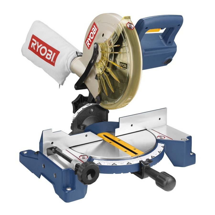
10 in. Compound Miter Saw
TS1342 - Double Insulated
Advertisement
Table of Contents

Related Manuals for Ryobi TS1342


Summary of Contents for Ryobi TS1342
- Page 1 OPERATOR’S MANUAL 10 in. Compound Miter Saw TS1342 - Double Insulated Your miter saw has been engineered and manufactured to our high standard for dependability, ease of operation, and op- erator safety. When properly cared for, it will give you years of rugged, trouble-free performance.
-
Page 2: Table Of Contents
The replacement power tool will be covered by the limited warranty for the balance of the two year period from the date of the original purchase. WHAT THIS WARRANTY COVERS: This warranty covers all defects in workmanship or materials in your RYOBI power ®... -
Page 3: General Safety Rules
GENERAL SAFETY RULES SECURE WORK. Use clamps or a vise to hold work WARNING: when practical, it is safer than using your hand and frees both hands to operate the tool. Read and understand all instructions. Failure to follow ... -
Page 4: Specific Safety Rules
GENERAL SAFETY RULES INSPECT TOOL CORDS PERIODICALLY. If USE ONLY CORRECT BLADES. Do not use blades with incorrect size holes. Never use blade washers or blade damaged, have repaired by a qualified service technician at an authorized service facility. The conductor with insulation bolts that are defective or incorrect. - Page 5 SPECIFIC SAFETY RULES NEVER reach behind, under, or within three inches of the MAKE SURE THE WORK AREA HAS AMPLE LIGHTING blade and its cutting path with hands and fingers for any to see the work and that no obstructions will interfere with reason.
-
Page 6: Symbols
SYMBOLS Some of the following symbols may be used on this tool. Please study them and learn their meaning. Proper interpretation of these symbols will allow you to operate the tool better and safer. SYMBOL NAME DESIGNATION/EXPLANATION Volts Voltage Amperes Current Hertz Frequency (cycles per second) - Page 7 If you do not understand ing, use only identical replacement parts. the warnings and instructions in the operator’s manual, do not use this product. Call Ryobi customer service for assistance. WARNING: The operation of any power tool can result in foreign objects being thrown into your eyes, which can result in severe eye damage.
-
Page 8: Electrical
ELECTRICAL DOUBLE INSULATION EXTENSION CORDS Double insulation is a concept in safety in electric power When using a power tool at a considerable distance from tools, which eliminates the need for the usual three- a power source, be sure to use an extension cord that has wire grounded power cord. -
Page 9: Glossary Of Terms
GLOSSARY OF TERMS Non-Through Cuts Anti-Kickback Pawls (radial arm and table saws) Any cutting operation where the blade does not extend A device which, when properly installed and maintained, completely through the thickness of the workpiece. is designed to stop the workpiece from being kicked back toward the front of the saw during a ripping operation. -
Page 10: Features
FEATURES PRODUCT SPECIFICATIONS Blade Arbor .............. 5/8 in. Cutting Capacity with Miter at 0°/Bevel 0°: Maximum nominal lumber sizes: ....2 x 6, 4 x 4 Blade Diameter ............10 in. Cutting Capacity with Miter at 45°/Bevel 0°: No Load Speed ........5,500 r/min. (RPM) Maximum nominal lumber sizes: ......2 x 4 Input ........120 V, 60 Hz, AC only, 15 Amps Cutting Capacity with Miter at 0°/Bevel 45°:... -
Page 11: Know Your Compound Miter Saw
FEATURES KNOW YOUR COMPOUND MITER SAW See Figure 1. The safe use of this product requires an understanding of the information on the tool and in this operator’s manual as CARRYING well as a knowledge of the project you are attempting. Before HANDLE use of this product, familiarize yourself with all operating features and safety rules. -
Page 12: Tools Needed
FEATURES POSITIVE STOPS ON MITER TABLE MITER FENCE Positive stops have been provided at 0 , 15 , 22-1/2 , 30 , and The miter fence on the compound miter saw has been ° ° ° ° . The 22-1/2 and 45 positive stops have been provided provided to hold the workpiece securely against when... -
Page 13: Loose Parts
LOOSE PARTS The following items are included with the tool: Miter Lock Handle Blade Wrench Dust Bag Operator’s Manual Work Clamp DUST BAG MITER LOCK HANDLE WORK CLAMP BLADE WRENCH Fig. 6 WARNING: The use of attachments or accessories not listed might be hazardous and could cause serious personal injury. -
Page 14: Assembly
ASSEMBLY UNPACKING WARNING: This product requires assembly. Carefully lift saw from the carton by the carrying handle and Do not start the compound miter saw without checking for the saw base, and place it on a level work surface. interference between the blade and the miter fence. -
Page 15: Work Clamp
ASSEMBLY MITER LOCK HANDLE MITER See Figure 8. LOCK HANDLE To install the miter lock handle, place the threaded stud on the end of the miter lock handle into the threaded hole in TIGHTEN the control arm. Turn clockwise to tighten. DUST BAG See Figure 9. - Page 16 ASSEMBLY TO INSTALL / REPLACE THE BLADE See Figures 11 - 12. WARNING: SPINDLE A 10 in. blade is the maximum blade capacity of the saw. LOCK BUTTON Never use a blade that is too thick to allow outer blade washer to engage with the flats on the spindle.
- Page 17 ASSEMBLY FRAMING WARNING: MITER SQUARE FENCE MITER TABLE Make sure the spindle lock button is not engaged before reconnecting saw into power source. Never engage spindle lock button when blade is rotating. NOTE: Many of the illustrations in this manual show only portions of the compound miter saw.
-
Page 18: Squaring The Saw Blade To The Fence
ASSEMBLY SQUARING THE SAW BLADE TO THE FENCE See Figures 16 - 20 BLADE MITER FENCE Unplug the saw. Pull the saw arm all the way down and engage the lock MITER pin to hold the saw arm in transport position. LOCK ... - Page 19 ASSEMBLY SQUARING THE BLADE TO THE MITER TABLE BEVEL See Figures 21 - 23. LOCK KNOB Unplug the saw. BLADE MITER Pull the saw arm all the way down and engage the lock FENCE pin to hold the saw arm in transport position. ...
-
Page 20: Operation
Ryobi dealer. Press the miter lock plate down with thumb and hold. WARNING:... - Page 21 OPERATION Rotate the control arm until the pointer aligns with the Loosen the bevel lock knob and move the saw arm to the left to the desired bevel angle. desired angle on the miter scale. Release the miter lock plate. ...
- Page 22 OPERATION Grasp the stock firmly with one hand and secure it against COMPOUND MITER CUT the fence. Use the optional work clamp or a C-clamp to secure the workpiece when possible. See Figure 26. Before turning on the saw, perform a dry run of the cutting operation just to make sure that no problems will occur when the cut is made.
- Page 23 OPERATION Grasp the stock firmly with one hand and secure it against the fence. Use the optional work clamp or a C-clamp to secure the workpiece when possible. Before turning on the saw, perform a dry run of the cutting operation just to make sure that no problems will occur when the cut is made.
-
Page 24: Cutting Compound Miters
OPERATION CUTTING COMPOUND MITERS To aid in making the correct settings, the compound angle setting chart below has been provided. Since compound cuts are the most difficult to accurately obtain, trial cuts should be made in scrap material, and much thought and planning made, prior to making the required cut. -
Page 25: Cutting Crown Molding
OPERATION CUTTING CROWN MOLDING When setting the bevel and miter angles for compound miters, remember that the settings are interdependent; changing The compound miter saw does an excellent job of cutting one angle changes the other angle as well. crown molding. In general, compound miter saws do a better Keep in mind that the angles for crown moldings are very job of cutting crown molding than any other tool made. -
Page 26: Operation
OPERATION Bevel Angle Type of Cut Setting Left side, inside corner 1. Top edge of molding against fence 33.85 ° 2. Miter table set right 31.62 ° 3. Save left end of cut Right side, inside corner 1. Bottom edge of molding against fence 33.85 °... -
Page 27: Adjustments
SCREW by itself. If the saw arm does not raise by itself or if there is play in the pivot joints, have saw repaired at your nearest RYOBI AUTHORIZED SERVICE CENTER. BEVEL PIVOT ADJUSTMENT The compound miter saw should bevel easily by loosening the bevel lock knob and tilting the saw arm to the left. -
Page 28: Maintenance
MAINTENANCE BRUSH WARNING: When servicing, use only identical Ryobi replacement parts. Use of any other parts may create a hazard or BRUSH cause product damage. ASSEMBLY WARNING:... - Page 29 NOTES...
-
Page 30: Parts Ordering / Service
When ordering repair parts, always give the following information: TS1342 • MODEL NUMBER • SERIAL NUMBER Ryobi is a registered trademark of Ryobi Limited used under license. ® ® ONE WORLD TECHNOLOGIES, INC. 1428 Pearman Dairy Road, Anderson, SC 29625 Phone 1-800-525-2579 www.ryobitools.com...