Table of Contents
Advertisement
Quick Links
Your miter saw has been engineered and manufactured to our high standard for dependability, ease of operation, and
operator safety. When properly cared for, it will give you years of rugged, trouble-free performance.
WARNING:
To reduce the risk of injury, the user must read and understand the operator's manual before using
this product.
Thank you for your purchase.
SAVE THIS MANUAL FOR FUTURE REFERENCE
OPERATOR'S MANUAL
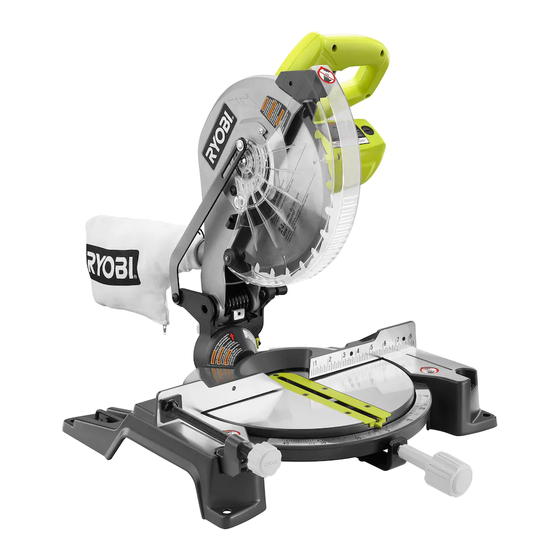
10 in. Compound Miter Saw
TS1345L - Double Insulated
Advertisement
Table of Contents

Related Manuals for Ryobi TS1345L


Summary of Contents for Ryobi TS1345L
- Page 1 OPERATOR’S MANUAL 10 in. Compound Miter Saw TS1345L - Double Insulated Your miter saw has been engineered and manufactured to our high standard for dependability, ease of operation, and operator safety. When properly cared for, it will give you years of rugged, trouble-free performance.
-
Page 2: Table Of Contents
The replacement power tool will be covered by the limited warranty for the balance of the three year period from the date of the original purchase. WHAT THIS WARRANTY COVERS: This warranty covers all defects in workmanship or materials in your RYOBI power ®... -
Page 3: General Safety Rules
GENERAL SAFETY RULES SECURE WORK. Use clamps or a vise to hold work WARNING: when practical, it is safer than using your hand and frees both hands to operate the tool. Read and understand all instructions. Failure to follow ... -
Page 4: Specific Safety Rules
GENERAL SAFETY RULES INSPECT TOOL CORDS PERIODICALLY. If bolts that are defective or incorrect. The maximum blade damaged, have repaired by a qualified service technician at capacity of your saw is 10 in. an authorized service facility. Repair or replace a damaged ... - Page 5 SPECIFIC SAFETY RULES NEVER reach behind, under, or within three inches of the MAKE SURE THE WORK AREA HAS AMPLE LIGHTING blade and its cutting path with hands and fingers for any to see the work and that no obstructions will interfere with safe operation BEFORE performing any work using the reason.
-
Page 6: Symbols
SYMBOLS The following signal words and meanings are intended to explain the levels of risk associated with this product. SYMBOL SIGNAL MEANING Indicates an imminently hazardous situation, which, if not avoided, will result DANGER: in death or serious injury. Indicates a potentially hazardous situation, which, if not avoided, could result WARNING: in death or serious injury. -
Page 7: Electrical
ELECTRICAL DOUBLE INSULATION EXTENSION CORDS Double insulation is a concept in safety in electric power When using a power tool at a considerable distance from tools, which eliminates the need for the usual three- a power source, be sure to use an extension cord that has wire grounded power cord. -
Page 8: Glossary Of Terms
GLOSSARY OF TERMS Anti-Kickback Pawls (radial arm and table saws) Push Blocks (for jointer planers) A device which, when properly installed and maintained, Device used to feed the workpiece over the jointer planer is designed to stop the workpiece from being kicked back cutterhead during any operation. -
Page 9: Features
FEATURES PRODUCT SPECIFICATIONS Blade Arbor ............... 5/8 in. Cutting Capacity with Miter at 0°/Bevel 0°: Maximum nominal lumber sizes: ....2 x 6, 4 x 4 Blade Diameter ............10 in. Cutting Capacity with Miter at 45°/Bevel 0°: No Load Speed ........5,500 r/min. (RPM) Maximum nominal lumber sizes: ......2 x 4 Input .......... - Page 10 FEATURES KNOW YOUR COMPOUND MITER SAW See Figure 1. The safe use of this product requires an understanding of the information on the tool and in this operator’s manual as well as a knowledge of the project you are attempting. Before use of this product, familiarize yourself with all operating LOCK features and safety rules.
-
Page 11: Tools Needed
FEATURES MITER LOCK HANDLE SPINDLE LOCK BUTTON See Figure 2. See Figure 3. The miter lock handle securely locks the saw at desired The spindle lock button locks the spindle stopping the blade miter angles. from rotating. Depress and hold the lock button while install- ing, changing, or removing blade. -
Page 12: Loose Parts
LOOSE PARTS The following items are included with the tool: Miter Lock Handle Blade Wrench Dust Bag AAA Batteries Work Clamp Operator’s Manual BATTERIES DUST BAG BLADE WRENCH MITER LOCK HANDLE WORK CLAMP Fig. 6 WARNING: The use of attachments or accessories not listed might be hazardous and could cause serious personal injury. -
Page 13: Assembly
ASSEMBLY UNPACKING WARNING: This product requires assembly. Do not connect to power supply until assembly is Carefully lift saw from the carton by the carrying handle and complete. Failure to comply could result in accidental start- the saw base, and place it on a level work surface. ing and possible serious personal injury. - Page 14 ASSEMBLY MITER LOCK HANDLE See Figure 8. To install the miter lock handle, place the threaded stud on the end of the miter lock handle into the threaded hole in the control arm. Turn clockwise to tighten. TIGHTEN DUST BAG See Figure 9.
- Page 15 ASSEMBLY INSTALLING BATTERIES FOR LASER LASER GUIDE See Figure 11. SWITCH BATTERIES Remove screw from battery compartment cover using the Phillips end of the supplied blade wrench. Remove COMPARTMENT cover and set aside. COVER Install two AAA batteries according to polarity indicators inside the battery compartment.
- Page 16 ASSEMBLY TO INSTALL / REPLACE THE BLADE See Figures 13 - 14. WARNING: A 10 in. blade is the maximum blade capacity of the saw. Larger blades will come in contact with the blade guards, SPINDLE while thicker blades will prevent the blade bolt from se- LOCK BUTTON curing the blade on the spindle.
- Page 17 ASSEMBLY SOCKET HEAD WARNING: SCREW(S) Make sure the spindle lock button is not engaged before reconnecting saw into power source. Never engage spindle lock button when blade is rotating. NOTE: Many of the illustrations in this manual show only portions of the compound miter saw. This is intentional so that we can clearly show points being made in the illustra- tions.
- Page 18 ASSEMBLY INDICATOR SCREW BLADE MITER FENCE MITER SCALE SCALE INDICATOR INDICATOR SCREW BEVEL SCALE MITER FRAMING SQUARE TABLE MITER LOCK HANDLE VIEW OF BLADE NOT SQUARE WITH FENCE, ADJUSTMENTS ARE REQUIRED Fig. 17 SCALE INDICATOR Fig. 19 BLADE MITER FENCE BLADE COMBINATION SQUARE...
- Page 19 ASSEMBLY SQUARING THE BLADE TO THE MITER TABLE See Figures 19 - 22. Unplug the saw. Pull the saw arm all the way down and engage the lock pin to hold the saw arm in transport position. Loosen the miter lock handle approximately one-half turn. BLADE ...
-
Page 20: Operation
OPERATION CUTTING WITH YOUR COMPOUND WARNING: MITER SAW Do not allow familiarity with tools to make you care- less. Remember that a careless fraction of a second is WARNING: sufficient to inflict serious injury. When using a work clamp or C-clamp to secure the workpiece, clamp workpiece on one side of the blade WARNING: only. - Page 21 OPERATION Once the saw arm has been set at the desired angle, Rotate the control arm until the pointer aligns with the desired angle on the miter scale. securely tighten the bevel lock knob. Tighten the miter lock handle securely. ...
- Page 22 OPERATION Grasp the stock firmly with one hand and secure it against COMPOUND MITER CUT the fence. Use the optional work clamp or a C-clamp to secure the workpiece when possible. See Figure 27. Before turning on the saw, perform a dry run of the cutting operation just to make sure that no problems will occur when the cut is made.
- Page 23 OPERATION Grasp the stock firmly with one hand and secure it against the fence. Use the optional work clamp or a C-clamp to secure the workpiece when possible. Before turning on the saw, perform a dry run of the cutting operation just to make sure that no problems will occur when the cut is made.
- Page 24 OPERATION CUTTING COMPOUND MITERS To aid in making the correct settings, the compound angle setting chart below has been provided. Since compound cuts are the most difficult to accurately obtain, trial cuts should be made in scrap material, and much thought and planning made, prior to making the required cut.
- Page 25 OPERATION CUTTING CROWN MOLDING When setting the bevel and miter angles for compound miters, remember that the settings are interdependent; changing The compound miter saw does an excellent job of cutting one angle changes the other angle as well. crown molding. In general, compound miter saws do a bet- Keep in mind that the angles for crown moldings are very ter job of cutting crown molding than any other tool made.
- Page 26 OPERATION Bevel Angle Type of Cut Setting Left side, inside corner 1. Top edge of molding against fence 33.9 ° 2. Miter table set right 31.6 ° 3. Save left end of cut Right side, inside corner 1. Bottom edge of molding against fence 33.9 °...
-
Page 27: Adjustments
The saw arm should rise completely to the up position by itself. If the saw arm does not raise by itself or if there is play in the pivot joints, have saw repaired at your nearest RYOBI AUTHORIZED SERVICE CENTER. BEVEL PIVOT ADJUSTMENT ... - Page 28 ADJUSTMENTS DANGER: Laser radiation. Avoid direct eye contact with light source. WARNING: LASER ADJUSTMENT Use of controls or adjustments or performance of pro- SCREW cedures other than those specified herein can result in hazardous radiation exposure. TO ADJUST THE LASER GUIDE LASER See Figure 34.
-
Page 29: Maintenance
MAINTENANCE BRUSH CAP WARNING: When servicing, use only identical replacement parts. Use of any other parts can create a hazard or cause product damage. BRUSH ASSEMBLY WARNING: Always wear eye protection with side shields marked to BRUSH CAP comply with ANSI Z87.1. Failure to do so could result in objects being thrown into your eyes, resulting in possible serious injury. - Page 30 When ordering repair parts, always give the following information: • MODEL NUMBER • SERIAL NUMBER RYOBI is a registered trademark of Ryobi Limited and is used pursuant to a license granted by Ryobi Limited. ONE WORLD TECHNOLOGIES, INC. 1428 Pearman Dairy Road, Anderson, SC 29625 Phone 1-800-525-2579 www.ryobitools.com...