Table of Contents
Advertisement
Your miter saw has been engineered and manufactured to Ryobi's high standard for dependability, ease of operation, and
operator safety. When properly cared for, it will give you years of rugged, trouble-free performance.
WARNING:
To reduce the risk of injury, the user must read and understand the operator's manual before using
this product.
Thank you for buying a Ryobi product.
SAVE THIS MANUAL FOR FUTURE REFERENCE
OPERATOR'S MANUAL
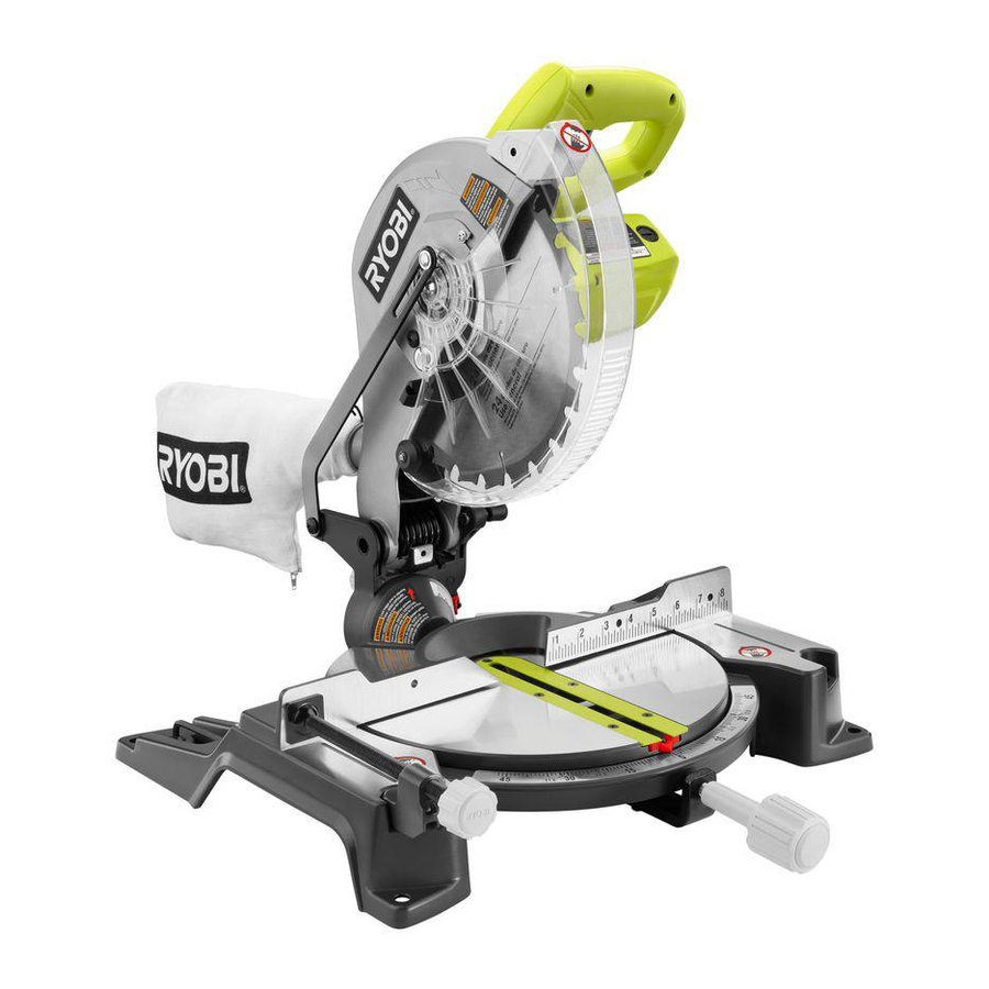
10 in. Compound Miter Saw
TS1341 - Double Insulated
Advertisement
Table of Contents

Related Manuals for Ryobi ts1341


Summary of Contents for Ryobi ts1341
- Page 1 Your miter saw has been engineered and manufactured to Ryobi’s high standard for dependability, ease of operation, and operator safety. When properly cared for, it will give you years of rugged, trouble-free performance. WARNING: To reduce the risk of injury, the user must read and understand the operator’s manual before using this product.
-
Page 2: Table Of Contents
n Introduction ... 2 n General Safety Rules ... 3-4 n Specific Safety Rules... 4-5 n Symbols... 6-7 n Electrical ... 8 n Glossary of Terms... 9 n Features... 10-12 n Tools Needed... 12 n Loose Parts ... 13 n Assembly ... 14-19 n Operation... -
Page 3: General Safety Rules
WARNING: Read and understand all instructions. Failure to follow all instructions listed below, may result in electric shock, fire and/or serious personal injury. READ ALL INSTRUCTIONS n KNOW YOUR POWER TOOL. Read the operator’s manual carefully. Learn the applications and limitations as well as the specific potential hazards related to this tool. -
Page 4: Specific Safety Rules
If a work clamp and length stop are used together, they must both be installed on the same side of the saw table to prevent the saw from catching the loose end and kicking up. - Page 5 NEVER leave the saw unattended while connected to a power source. n TURN OFF TOOL and wait for saw blade to come to a complete stop before moving workpiece or changing settings.
-
Page 6: Symbols
Some of the following symbols may be used on this tool. Please study them and learn their meaning. Proper interpreta- tion of these symbols will allow you to operate the tool better and safer. SYMBOL NAME Volts Amperes Hertz Watt Minutes Alternating Current Direct Current... -
Page 7: Save These Instructions
The following signal words and meanings are intended to explain the levels of risk associated with this product. SYMBOL SIGNAL DANGER: WARNING: CAUTION: CAUTION: SERVICE Servicing requires extreme care and knowledge and should be performed only by a qualified service technician. For service we suggest you return the product to your nearest AUTHORIZED SERVICE CENTER for repair. -
Page 8: Electrical
DOUBLE INSULATION Double insulation is a concept in safety in electric power tools, which eliminates the need for the usual three- wire grounded power cord. All exposed metal parts are isolated from the internal metal motor components with protecting insulation. Double insulated tools do not need to be grounded. -
Page 9: Glossary Of Terms
The area over, under, behind, or in front of the blade. As it applies to the workpiece, that area which will be or has been cut by the blade. The distance that the tip of the saw blade tooth is bent (or set) outward from the face of the blade. Snipe (planers) Depression made at either end of a workpiece by cutter blades when the workpiece is not properly supported. -
Page 10: Features
Cutting Capacity with Miter at 0°/Bevel 45°: Maximum nominal lumber sizes: ...2 x 6 Cutting Capacity with Miter at 45°/Bevel 45°: Maximum nominal lumber sizes: ...2 x 4 BASE POSITIVE STOP(S) SAW ARM SWITCH TRIGGER LOWER BLADE GUARD THROAT PLATE “NO HANDS ZONE”... -
Page 11: Know Your Compound Miter Saw
To transport, turn off and unplug the saw, then lower the saw arm and lock it in the down position. Lock saw arm by depressing the lock pin. -
Page 12: Tools Needed
SELF-RETRACTING LOWER BLADE GUARD The lower blade guard is made of shock-resistant, see- through plastic that provides protection from each side of the blade. It retracts over the upper blade guard as the saw is lowered into the workpiece. SUPPORT FOOT A swingout support foot has been added to provide additional stability for the miter saw. -
Page 13: Loose Parts
The following items are included with the tool: n Miter Lock Handle n Dust Bag n Work Clamp DUST BAG WARNING: The use of attachments or accessories not listed might be hazardous and could cause serious personal injury. LOOSE PARTS n Blade Wrench n Operator’s Manual n Warranty Registration Card... -
Page 14: Assembly
This saw has been shipped with the saw arm secured in the down position. To release the saw arm, push down on the top of the saw arm, cut the tie-wrap, and pull out on the lock pin. n Lift the saw arm by the handle. Hand pressure should remain on the saw arm to prevent sudden rise upon release of the tie wrap. -
Page 15: Work Clamp
Turn clockwise to tighten. DUST BAG See Figure 9. A dust bag is provided for use on the miter saw. It fits over the exhaust port on the upper blade guard. To install it, remove dust guide from exhaust port. Then, squeeze the two metal clips to open the mouth of the bag and slide it on the exhaust port. - Page 16 See Figures 11 - 12. WARNING: A 10 in. blade is the maximum blade capacity of the saw. Never use a blade that is too thick to allow outer blade washer to engage with the flats on the spindle. Larger...
- Page 17 FENCE See Figures 13 - 16. n Unplug the saw. n Push down on the saw arm and pull out the lock pin to release the saw arm. n Raise saw arm to its full raised position. n Loosen the miter lock handle approximately one-half turn.
-
Page 18: Squaring The Saw Blade To The Fence
SQUARING THE SAW BLADE TO THE FENCE See Figures 16 - 20 n Unplug the saw. n Pull the saw arm all the way down and engage the lock pin to hold the saw arm in transport position. n Loosen the miter lock handle approximately one-half turn. - Page 19 SQUARING THE BLADE TO THE MITER TABLE See Figures 21 - 23. n Unplug the saw. n Pull the saw arm all the way down and engage the lock pin to hold the saw arm in transport position. n Loosen the miter lock handle approximately one-half turn.
-
Page 20: Operation
NOTE: The blade provided is fine for most wood cutting operations, but for fine joinery cuts or cutting plastic, use one of the accessory blades available from the Ryobi dealer. WARNING: Before starting any cutting operation, clamp or bolt the compound miter saw to a workbench. - Page 21 0° and 45°. n Pull out the lock pin and lift saw arm to its full height. n Loosen the miter lock handle. Rotate the miter lock handle approximately one-half turn to the left to loosen.
- Page 22 Pull out the lock pin and lift saw arm to its full height. n Loosen the miter lock handle. Rotate the miter lock handle approximately one-half turn to the left to loosen.
- Page 23 Use the optional work clamp or a C-clamp to secure the workpiece when possible. n Before turning on the saw, perform a dry run of the cutting operation just to make sure that no problems will occur when the cut is made.
-
Page 24: Cutting Compound Miters
CUTTING COMPOUND MITERS To aid in making the correct settings, the compound angle setting chart below has been provided. Since compound cuts are the most difficult to accurately obtain, trial cuts should be made in scrap material, and much thought and planning made, prior to making the required cut. -
Page 25: Cutting Crown Molding
CUTTING CROWN MOLDING The compound miter saw does an excellent job of cutting crown molding. In general, compound miter saws do a better job of cutting crown molding than any other tool made. In order to fit properly, crown molding must be compound mitered with extreme accuracy. -
Page 26: Cutting Warped Material
Bevel Angle Type of Cut Setting Left side, inside corner 1. Top edge of molding against fence 33.85 ° 2. Miter table set right 31.62 3. Save left end of cut Right side, inside corner 1. Bottom edge of molding against fence 33.85 °... -
Page 27: Adjustments
The saw arm should rise completely to the up position by itself. n If the saw arm does not raise by itself or if there is play in the pivot joints, have saw repaired by at your nearest RYOBI AUTHORIZED SERVICE CENTER. -
Page 28: Maintenance
Loosen the bevel lock knob by turning the knob counterclockwise. WARNING: When servicing, use only identical Ryobi replacement parts. Use of any other parts may create a hazard or cause product damage. WARNING:... - Page 29 NOTES...
-
Page 30: Parts Ordering / Service
Ryobi Authorized Service Center. Be sure to provide all pertinent facts when you call or visit. Please call 1-800-525-2579 for your nearest Ryobi Authorized Service Center. You can also check our web site at www.ryobitools.com for a complete list of Authorized Service Centers.