Table of Contents
Advertisement
White
Rodgers
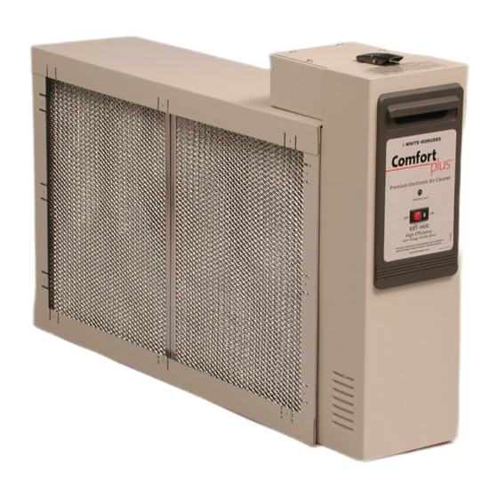
plus
Electronic
Air Cleaner
Model Number
SS !
SST1000
SST1400
SST1600
SST2000
LISTED
OWNER'S
MANUAL
• Installation
• Operation
• Basic SST
Service
Guide
• Technical
Repair
Guide
• Repair
Parts
Please read and familiarize
yourself with the contents of this manual before
installing, operating or performing
maintenance
on the unit.
)
J
EMERSON
Climate
Tech_o_o_ie_
White-Rodgers is a division
of Emerson Etect_icCo.
www.white-rodgers.com
PART
NO. 37-6373F
Replaces 37-6373E
0631
Advertisement
Table of Contents

Related Manuals for White Rodgers SST1600

Summary of Contents for White Rodgers SST1600
- Page 1 White Rodgers plus Electronic Air Cleaner Model Number SS ! SST1000 SST1400 SST1600 SST2000 LISTED OWNER'S MANUAL • Installation • Operation • Basic SST Service Guide • Technical Repair Guide • Repair Parts Please read and familiarize yourself with the contents of this manual before installing, operating or performing maintenance on the unit.
- Page 2 RULES FOR SAFE INSTALLATION AND OPERATION If this unit has an electrical cord, the cord has a grounding type plug with a third (grounding) pin. This plug will fit only into a grounding type power outlet. If the proper type of outlet is not Please read instructions before installing and using the Elec- available, contact qualified personnel to install a proper outlet.
- Page 3 HOW THE AIR CLEANER WORKS Dirt particles flowing through the ducts (Figure 1) first enters the pre-filters (A) where large particles (hair, lint, etc.) are Clean Air Out trapped. Smaller particles (smoke, dust, pollen, etc.) pass through these pre-filters and enter the ionizing section (B). Here each tiny particle receives a positive electrical charge.
-
Page 4: Pre-Installation
PREINSTALLATION (Interchangeable) (Interchangeable) Collecting Cell Collecting Cell Not to Exceed 20 </> Air Flow Cabinet Outlet Box Power Pack Handle © (_:]Air Flow Furnace / Opening Contact Electronic Button , Air Cleaner Pre-Filters Contact Opening (Interchangeable) Button See text for Cell Removal Clearance Electronic Furnace... - Page 5 TYPICAL MOUNTING POSITIONS Air Flow <p- Air Flow Air Flow View Rear View Figure 6 Figure 8 Figure 7 BASEMENT FURNACE HIGHBOY FURNACE COUNTERFLOW (LOWBOY) (Figure 6) (Figure 8) FURNACE (Figure 7) Cleaner is mounted hori- Side installation. Cleaner Cleaner is mounted horizontally in re- zontally in return plenum, is mounted vertically,...
-
Page 6: Installation
INSTALLATION REMOVE OLD FILTER AND DISCARD (Figure 12) NOTE: This filter may be mounted in the furnace compart- ment. CLEAN BLOWER COMPARTMENT It is suggested that the furnace blower compartment, Figure 12 blower and blower housing be cleaned to ensu re clean air circulation. -
Page 7: Wiring Instructions
WIRING INSTRUCTIONS 10. If this unit has an electrical cord, the cord has a With the cabinet installed, the air cleaner can now be wired to electrical input source. grounding type plug with a third (grounding) pin. This plug will fit only into a grounding type power outlet. If the proper type of outlet is not available, contact qualified personnel to install a proper outlet. -
Page 8: Operation
OPERATION With the 120 VAC power turned on at the circuit breaker for the fu mace, push the air cleaner ON-OFF switch to the "ON" position (Figure 20). With thefurnace blower running, the aircleanerwill operating. An arcing or "snapping" sound may be heard. -
Page 9: Specifications
REPLACING AN IONIZING WIRE If an ionizing wire should break, it can be replaced as follows: Remove all pieces of broken wire. Make sure sup- ports at each end are in good condition and not bent out of shape. Hook the new wire onto the support at one end. Hold your finger against the support at the other end (Figure 21) and hold the ionizing wire between thumb and forefinger as shown or use needle nose pliers. - Page 10 BASIC SST SERVICE GUIDE This guide will cover most homeowner complaints. If, after checking the items listed, the unit still fails to operate properly, contact the nearest Authorized Service Center. SERVICE INDICATION SERVICE CHECKS ON/OFF switch "ON" Unit functioning Normally Blower ON Operating Light ON ON/OFF switch "ON"...
-
Page 11: Repair Guide
TECHNICAL REPAIR GUIDE All voltage measurements indicated can be made with a high voltage D.C. probe and a general purpose volt ohm Do not attempt repair of this unit unless you are meter. For example: Simpson 260 or equivalent. familiarwith the necessarytools, equipment, utility... - Page 12 POWER SUPPLY Using a standard extension cord, apply 120 VAC to power pack. Turn power switch to "ON" position. CHECKOUT PROCEDURE Connect meter negative (-) lead to metal frame of Turn power switch to the "OFF" position and remove collecting cell. Use high voltage probe to measure the power pack from cabinet.
- Page 13 OZONE REDUCTION All electronic air cleaners typically produce a small amount of ozone that is within established limits. Some customers may notice an odor especially at high altitudes or low air flow rates. This power supply has a "hairpin" shaped jumper wire labeled W1 (see Fig 24) that can be cut and ""...
- Page 14 RE PAl R PARTS...
-
Page 15: Repair Parts
RE PAl R PARTS PARTS LIST FOR ELECTRONIC AIR CLEANERS When ordering repair parts, always give the following information as shown in this list. 1. The PART NUMBER 2. The PART DESCRIPTION 3. The MODEL NUMBER 4. The NAME OF ITEM - Electronic Air Cleaner. Always order by "PART NUMBER"... -
Page 16: Notice To Consumers
WASH REMINDER SCHEDULE frequent washing may be necessary on some installations scheduleis necessaryto ensure proper regular washing where there is new carpeting, plaster dust or excessive washing once every month will be efficiency. A thorough cigarette smoke, etc. (See page 8 for maintenance for most installations.