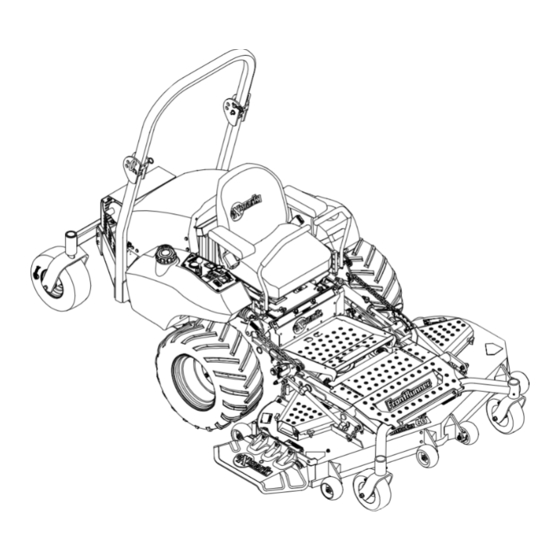
Exmark Frontrunner Operating Manual
Exmark zero-turn riding mower operating manual frontrunner
Hide thumbs
Also See for Frontrunner:
- Parts manual (28 pages) ,
- Operator's manual (52 pages) ,
- Setup instructions (4 pages)
Table of Contents
Advertisement
CONGRATULATIONS on the purchase of your new Exmark mower. This product has been carefully designed and manufactured to give you
a maximum amount of dependability and years of trouble-free operation. If additional information is needed, or should you require trained
mechanic service, contact your authorized Exmark equipment dealer or distributor. If you need to order replacement parts from your dealer,
always give the model number and serial number of your mower as well as the part number, description and quantity of the part needed.
The Serial No. Plate on the right side of the unit under the fuel tank. For ease of ordering and reference, we suggest that you record the
information requested in the following identification table.
Place Model No. and Serial No. Label Here
(Included in Literature Pack)
or Fill in Below
Model No.
Serial No.
Engine Model No. and Spec. No. (Code)
Engine Serial No. (E/No)
Date Purchased
For Serial Nos.
670,000 & Higher
TM
Part No. 109-4334 Rev. A
Advertisement
Table of Contents

Related Manuals for Exmark Frontrunner


Summary of Contents for Exmark Frontrunner
- Page 1 CONGRATULATIONS on the purchase of your new Exmark mower. This product has been carefully designed and manufactured to give you a maximum amount of dependability and years of trouble-free operation. If additional information is needed, or should you require trained mechanic service, contact your authorized Exmark equipment dealer or distributor.
- Page 2 POTENTIAL HAZARD ♦ This product is a piece of power equipment. WHAT CAN HAPPEN ♦ Failure to follow safe operating practices can result in serious operator injury or even death. HOW TO AVOID THE HAZARD ♦ Keep all shields, guards, and safety devices (especially the grass discharge system) in place and in proper working condition.
- Page 3 3. Exmark being unable to ship the part and the Exmark parts order is received by 3:00 p.m., central time, Exmark pays for the part and freight. 4. If the part does not arrive overnight due to the shipper (UPS), the shipper pays for the freight and Exmark pays for the part.
- Page 4 If additional information is needed, or should you require trained mechanic service, contact your authorized Exmark equipment dealer or distributor. All Exmark equipment dealers and distributors are kept informed of the latest methods of servicing and are equipped to provide prompt and efficient service in the field or at their service stations.
-
Page 5: Table Of Contents
1. SAFETY Safety Alert Symbol ... 1 Training ... 1 Preparation... 1-3 Operation ... 4-7 Maintenance & Storage ... 8-9 Safety Signs ... 9-11 2. SPECIFICATIONS Model Number ... 12 Engine ... 12 Fuel System ... 12 Electrical System ... 12 Cooling System ... -
Page 6: Safety Alert Symbol
MAY result in minor or moderate injury. 1.2 TRAINING 1.2.1 Regard the Exmark mower as a piece of power equipment and teach this regard to all who operate this unit. 1.2.2 Read the instructions carefully. Familiarize yourself with the controls and the proper use of the equipment. - Page 7 POTENTIAL HAZARD ♦ This machine produces sound levels in excess of 85 dBA at the operator’s ear when in operation. WHAT CAN HAPPEN ♦ Exposure to sound levels of 85 dBA or above for extended periods of time can cause hearing loss. HOW TO AVOID THE HAZARD ♦...
- Page 8 DANGER POTENTIAL HAZARD ♦ Diesel fuel is flammable. WHAT CAN HAPPEN ♦ A fire from diesel fuel can burn you, others, and cause property damage. HOW TO AVOID THE HAZARD ♦ DO NOT smoke while refueling, and stay away from an open flame or where fuel fumes may be ignited by spark.
-
Page 9: Operation
1.4 OPERATION Although hazard control and accident prevention are partially dependent upon the design and configuration of the equipment, these factors are also dependent upon the awareness, concern, prudence, and proper training of the personnel involved in the operation, transport, maintenance, and storage of the equipment. It is essential that all Operator Safety Mechanisms be connected and in operating condition prior to use for mowing. - Page 10 1.4.3 When feasible, avoid operating the equipment in wet grass. POTENTIAL HAZARD ♦ Operating a FrontRunner tractor without an approved Exmark front mount attachment increases the possibility of forward tip over. WHAT CAN HAPPEN ♦ Tip-over could cause serious injury or death.
- Page 11 • See inside the back cover to determine the approximate slope angle of the area to be mowed. • Use a walk behind mower and/or a hand trimmer near drop-offs, ditches, steep banks or water. This area can be dangerous, see Figure 1. •...
- Page 12 • Be certain that the seat belt can be released quickly if the machine is driven or rolls into ponds of water. • Check carefully for overhead clearances (i.e. branches, doorways, and electrical wires) before driving under any objects and do not contact them. 1.4.6 Use EXTREME caution when backing up.
-
Page 13: Maintenance & Storage
1.5 MAINTENANCE AND STORAGE 1.5.1 For engine maintenance, follow the engine manufacturer’s recommendations precisely as stated in the engine manual. 1.5.2 Disconnect the battery cable from the negative battery post when the unit will be allowed to sit for more than 30 days without use. 1.5.3 Allowing batteries to stand for an extended period of time without recharging them will result in reduced performance and service life. -
Page 14: Safety Signs
POTENTIAL HAZARD ♦ Hydraulic fluid escaping under pressure can penetrate skin and cause injury. WHAT CAN HAPPEN ♦ Fluid accidentally injected into the skin must be surgically removed within a few hours by a doctor familiar with this form of injury or gangrene may result. - Page 15 1.6.3 When new components are installed, be sure that current safety signs are affixed to the replaced components. 1.6.4 New safety signs may be obtained from Exmark Mfg. Co. Inc. 1.6.5 Safety signs may be affixed by peeling off the backing to expose the adhesive surface.
- Page 16 PART NO. 107-2112 LOCATION: Top of Floor Pan PART NO. 109-2377 LOCATION: On Hydraulic Cylinder PART NO. 107-2102 LOCATION: Inside Surface of Upper Roll PART NO. 109-3637 LOCATION: Back of Seat PART NO. 109-2355 LOCATION: Outside of each Weight Transfer Bell Crank PART NO.
-
Page 17: Specifications
2. SPECIFICATIONS 2.1 MODEL NUMBER: 2.2 ENGINE 2.2.1 Engine Specifications: See your Engine Owner’s Manual 2.2.2 RPM: Full Speed: 3870 RPM (No Load) +50/-100 RPM Idle: 1400 RPM (No Load) ±50 RPM 2.3 FUEL SYSTEM 2.3.1 Capacity: 8.5 gal (32 L) 2.3.2 Type of Fuel: Diesel fuel, 40 cetane or higher. -
Page 18: Seat
2.7.3 Seat Safety Switch: Internal to the bottom seat cushion, non serviceable. Time delay module incorporated into the Safety Interlock System eliminates rough ground cut-outs. 2.7.4 Armrests: Standard seat: foam padded flip-up armrests. Optional suspension seat: molded adjustable flip-up armrests. 2.8 HYDROSTATIC GROUND DRIVE SYSTEM 2.8.1 Hydrostatic Pumps: Two Hydro Gear PR 16 cc variable displacement piston pumps. -
Page 19: Torque Requirements
2.12 TORQUE REQUIREMENTS Bolt Location Wheel Lug Nuts ...90-95 ft-lbs. (122-129 N-m) Wheel Motor Mounting Bolts...72-77 ft-lbs. (98-104 N-m) Rollover Protection System (Roll Bar) Mounting Bolts ...30-35 ft-lbs. (41-47 N-m) Clutch Retaining Bolt (secured with threadlocker)...55-60 ft-lbs. (75-81 N-m) Wheel Hub Slotted Nut ...minimum 125 ft-lbs. (169 N-m) 3. - Page 20 Pulling the levers back from the neutral position will cause the respective drive wheels to rotate in a reverse direction (spring tension can be felt when moving into reverse from neutral). To turn to the left while backing, move the left lever forward toward neutral. To turn to the right while backing, move the right lever forward toward neutral.
- Page 21 NOTE: A glow plug light, located to the rear of the glow plug switch, will illuminate when the switch is depressed. The glow plug light indicates the glow plugs are preheating the combustion chamber. 3.1.8 Hour Meter: Located on the right fuel tank console. The hour meter runs when the alternator is charging and it records the number of hours that the engine has run.
-
Page 22: Pre-Start
3.1.15 Alternator Charging Light: Located to the rear of the key switch. Light will come on when the alternator is not charging. 3.1.16 Low Oil Pressure Light: Located to the rear of the key switch with the alternator light. Light will come on when engine oil pressure is low or lost. NOTE: This switch is not a low oil level sensor and will not alert the operator if the engine oil level is low. - Page 23 d) Move the throttle to the “SLOW” (if in “MIDWAY”) and let the engine warm up a few minutes before moving the throttle to the “FAST” position. 3.3.3 Engaging PTO: POTENTIAL HAZARD ♦ The rotating blades under the mower deck are dangerous. WHAT CAN HAPPEN ♦...
-
Page 24: Transporting
3.4 TRANSPORTING IMPORTANT: Do not transport FrontRunner tractor without an approved Exmark front mount attachment. 3.4.1 Transporting a Unit: Use a heavy-duty trailer or truck to transport the machine. Engage the park brake and block the wheels. Securely fasten the machine to the trailer or truck with straps, chains, cable, or ropes. - Page 25 POTENTIAL HAZARD ♦ Loading a unit on a trailer or truck increases the possibility of tip-over. WHAT CAN HAPPEN ♦ Tip-over of the unit could cause serious injury or death. HOW TO AVOID THE HAZARD ♦ Use extreme caution when operating a unit on a ramp.
-
Page 26: Maintenance & Adjustments
4. MAINTENANCE & ADJUSTMENTS POTENTIAL HAZARD ♦ While maintenance or adjustments are being made, someone could start the engine. WHAT CAN HAPPEN ♦ Accidental starting of the engine could seriously injure you or other bystanders. HOW TO AVOID THE HAZARD ♦... - Page 27 4.1.2 Check engine coolant level: Service Interval: Daily Stop engine and wait for all moving parts to stop. Make sure machine is on a level surface. Tilt seat up and tilt hood forward to gain access to the cooling area. Check with engine cold.
- Page 28 recommended time interval to bring the charge up to a full charge of 12.6 volts or greater. IMPORTANT: Make sure the negative battery cables are disconnected and the battery charger used for charging the battery has an output of 16 volts and 7 amps or less to avoid damaging the battery (see chart below for recommended charger settings).
- Page 29 The PTO must not engage. NOTE: If machine does not pass any of these tests, do not operate. Contact your authorized EXMARK SERVICE DEALER. IMPORTANT: It is essential that operator safety mechanisms be connected and in proper operating condition prior to use for mowing.
- Page 30 4.1.9 Service air cleaner: First Service Interval: 50 hrs. Normal Interval: 100 hrs Replacement Interval: 600 hrs (More often under severe conditions.) See Engine manual for additional information. Stop engine, wait for all moving parts to stop, and remove key. Engage parking brake.
- Page 31 Drain coolant when engine is cool. Coolant may be drained from the radiator by loosening the drain cock in the left rear corner. The engine block may be drained by removing the lower radiator hose and/or by opening the drain cock from the engine block.
- Page 32 f) Operate engine until the engine thermostat opens and coolant is circulating through the radiator core. As air is purged from the engine block and the coolant level drops, add additional coolant to the radiator. g) When the radiator is completely full and no additional coolant can be added, continue running the engine and install the radiator cap.
- Page 33 AT101 (Bar Lug) drive tires should be inflated to 9 psi (62 kpa). Turfmate drive tires should be inflated to 13 psi (90 kpa). The rear caster tires are semi-pneumatic and do not need to be inflated. NOTE: Do not add any type of tire liner or foam fill material to the tires. Excessive loads created by foam filled tires may cause failures to the hydro drive system, frame, and other components.
- Page 34 Pack the bearings with a NGLI grade #1 multi-purpose grease. Insert (1) bearing, (1) new seal into the wheel. NOTE: Seals (Exmark PN 103-0063) must be replaced. If the axle assembly has had both spacer nuts removed (or broken loose), apply a thread locking adhesive to (1) spacer nut and thread onto the axle with the wrench flats facing outward.
- Page 35 4.1.20 Lubricate the motion control bronze bushings: Service Interval: 160 hrs. Stop engine, wait for all moving parts to stop, and remove key. Engage parking brake. Tilt seat forward. Lubricate bronze bushings on the flange bearings securing the motion control arm shafts with a light oil or a spray type lubricant. 4.1.21 Lubricate the motion control shaft: Service Interval: Yearly.
- Page 36 Change hydraulic system filter: First Interval: 250 hrs. Normal Interval: Yearly. NOTE: Use only Exmark Part No.103-2146 Stop engine, wait for all moving parts to stop, and remove key. Engage parking brake. Carefully clean area around filter. It is important that no dirt or contamination enter hydraulic system.
-
Page 37: Adjustments
4.1.27 Wheel Hub – lock nut torque specification Service Interval: After First 100 hrs Then every 500 hrs thereafter When tightening the lock nut on the wheel motor tapered shaft: Torque the lock nut to 125 ft-lbs (169 N-m). NOTE: Do not use antisieze on wheel hub. 4.1.28 Fuel Tank –... - Page 38 To tighten alternator belt, loosen both upper and lower alternator mounting bolts. Rotate alternator out, away from engine and re-tighten hardware to secure in place. When properly tensioned, the alternator belt will deflect 1/4”-3/8” (7-9 mm) while applying 22 pounds of force to the belt midway between alternator and crankshaft pulley.
- Page 39 h) If the linkage does not measure 7-3/8” (18.7 cm) or still does not disengage as desired, remove the bolt that secures the ball joint to the brake lever and loosen the jam nut next to the ball joint. Rotate the ball joint in half-turns counter-clockwise until desired disengagement is obtained.
- Page 40 Set neutral: Remove the electrical connection from the seat safety switch, located directly in front of the seat switch assembly. The neutral adjustment must be made with the drive wheels turning. Raise the frame and place on jack stands so that drive wheels can rotate freely. Temporarily install a jumper wire across the terminals in the connector of the wiring harness.
- Page 41 Check where lever is relative to notch in neutral plate (should be centered allowing lever to pivot outward to the neutral lock position). If adjustment is needed, loosen the nut against the yoke and while applying slight rearward pressure on the motion control lever, turn the head of the adjustment bolt in the appropriate direction until lever is centered (keeping rearward pressure on the lever will keep the pin at the end of the slot and allow the adjustment bolt to move the lever to the appropriate position).
- Page 42 WARNING POTENTIAL HAZARD ♦ Weight transfer springs may have stored energy. WHAT CAN HAPPEN ♦ Removing the weight transfer springs without releasing the stored energy can cause serious injury HOW TO AVOID THE HAZARD ♦ Fold mower deck and front frame and lock in service position to remove spring tension and release stored energy before performing any maintenance or...
-
Page 43: Waste Disposal
POTENTIAL HAZARD ♦ Raising the unit for service or maintenance relying solely on mechanical or hydraulic jacks could be dangerous. WHAT CAN HAPPEN ♦ The mechanical or hydraulic jacks may not be enough support or may malfunction allowing the unit to fall, which could cause injury. -
Page 44: Troubleshooting
NOTE: After carefully checking the above steps, attempt to start the engine. If it does not start, contact your authorized Exmark service dealer. IMPORTANT: It is essential that all operator safety mechanisms be connected and in proper operating condition prior to mower use. -
Page 45: Engine Warning Systems
PROBLEM Will not start Hard starting Stops suddenly Lacks power Operates erratically Skips or misfires Overheats High fuel consumption 6.4 ENGINE WARNING SYSTEMS 6.4.1 Alternator Charging Light: Located to the rear of the key switch. Light will come on when the alternator is not charging. 6.4.2 Low Oil Pressure Light: Located to the rear of the key switch with the alternator light. -
Page 46: Electrical Diagram
7. ELECTRICAL DIAGRAM... -
Page 47: Hydraulic Diagram
8. HYDRAULIC DIAGRAM... -
Page 48: Warranty
Company, pursuant to an agreement between them, jointly warrant on the terms and conditions herein, that we will repair, replace or adjust any part manufactured by Exmark and found by us (in the exercise of our reasonable discretion) to be defective in factory materials or workmanship for a period of two years. - Page 49 NOTES...
- Page 50 NOTES...
- Page 52 The engine exhaust from this product contains chemicals known to the State of California to cause cancer, birth defects, or other reproductive harm. ©2006-2007 EXMARK MFG. CO. INC. INDUSTRIAL PARK BOX 808 BEATRICE, NE 68310 ALL RIGHTS RESERVED LINE OF ACCESSORIES...