Advertisement
Quick Links
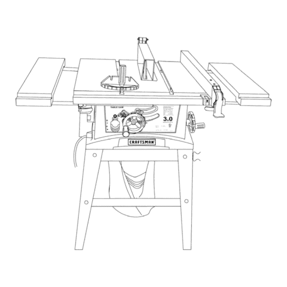
Operator's Manual
gN ,®
3.0 HP (Max. Developed)
10" Inch Blade
5000 R.P.M.
TABLE SAW
Model No.
137.248880
CAUTION:
Before using this Table Saw,
read this manual and follow
all its Safety Rules and
Operating Instructions
•
Safety Instructions
•
Installation
•
Operation
•
Maintenance
•
Parts List
Customer
Help Line
1-800-843-1682
Sears, Roebuck and Co., Hoffman Estates, IL 60179 USA
Visit our Craftsman website: www.sears.com/craftsman
Part No. 13724888001
Advertisement

Related Manuals for Craftsman 137.248880


Summary of Contents for Craftsman 137.248880
- Page 1 • Operation all its Safety Rules and • Maintenance Operating Instructions • Parts List Customer Help Line 1-800-843-1682 Sears, Roebuck and Co., Hoffman Estates, IL 60179 USA Visit our Craftsman website: www.sears.com/craftsman Part No. 13724888001...
- Page 2 SECTION PAGE SECTION PAGE Know Your Table Saw ....... Warranty ........Product Specifications ....... Assembly and Adjustments ....Power Tool Safety ......Operation ........Maintenance ........Table Saw Safety ......Electrical Requirements and Safety ..Troubleshooting Guide ....... Accessories and Attachments ....Parts List ........
- Page 3 I_ WARNING] Before using your table saw, it is critical that you read and understand these safety rules. Failure to follow these rules could result in serious injury or damage to the table saw. REMOVE ADJUSTING KEYS AND WRENCHES. Good safety practices are a combination of common sense, staying alert and understanding how to use your Form the habit of checking to see that keys and power tool.
- Page 4 PROVIDE ADEQUATE SUPPORT to the rear and ALWAYS USE SAW BLADE GUARD, splitter and anti-kickback pawls for every operation for which they the sides of the saw table for long or wide workpieces. can be used, including through sawing. Through sawing operations are those in which the blade cuts AVOID KICKBACKS (work thrown back towards you) completely through the workpiece when ripping or...
- Page 5 GROUNDING INSTRUCTIONS POWER SUPPLY REQUIREMENTS I A WARNING] IN THE EVENT OF A MALFUNCTION OR BREAKDOWN, grounding provides a path of least To avoidelectrical hazards, fire h azardsor damage tothe resistance for electric current and reduces the risk of table saw, use propercircuit protection.
- Page 6 "Table Visit your Sears Hardware Department or see the of Loose Parts" to make certain all items are accounted Craftsman Power and Hand Tools Catalog to purchase for, before discarding any packing material. recommended accessories for this power tool.
- Page 7 UNPACKING YOUR TABLE SAW...
- Page 8 Table Insert Blade Guard Rip Fence SideTable Extension Table lock handles Blade Tilting Handwheel Blade tilt pointer Overload reset Blade bevel switch lock knob Blade tilt scale Blade elevation handwheel ON/OFF switch with key Fence storage Miter Gauge Table Rear Table Extension Mounting...
- Page 9 NOTE: Do not tighten bolts until stand is properly aligned NOTE: Make sure front of stand (identified with (see step #9). Craftsman label) and front of saw are facing the Attach other end of long upper support to top of another same direction.
- Page 10 SAW MOUNTED TO WORK SURFACE (FIG. C) Place the dust bag neck opening around the dust chute 1. If the leg set will not be used, the saw must be and tie the dust bag with string. properly secured to a sturdy workbench using the Fig.
- Page 11 RIP FENCE (Fig. G) 2. Raise the blade arbor (4) (Fig. I) to the maximum 1. Lift upward on the rip fence handle (1) so that the height by turning the blade raising handwheel counterclockwise. holding clamp (2) is fully extended. 2.
- Page 12 WARNING I BLADE GUARD ASSEMBLY (FIG. K, L, M) 1. Set the blade to maximum height and the tilt to Improper splitter alignment can cause zero degrees on the bevel scale with the hand "kickback" and serious injury. wheels. Lock the blade lock knob. 2.
- Page 13 INSTALLING TABLE SIDE EXTENSIONS- cont'd ADJUSTING REAR TABLE EXTENSION (FIG. O) Rear table extension should be positioned as close 6. Snap one location seat (5) over the end of the rear as possible to the rear of the table when ripping table extension tube (3).
- Page 14 RIP FENCE INDICATOR ADJUSTMENT (FIG. Q) Fig. Q-2 1. The rip fence indicator (6) points to the measurement scale (8). The scale shows the distance from the side of the fence to nearest side 90 ° 45 ° of the blade. 2.
- Page 15 BLADE PARALLEL TO THE MITER GAUGE Additional blade adjustments (Fig. S) GROOVE (FIG. R,S) The adjusting mechanism is located on top of blade I_WARNING I height adjusting hand wheel under the tabletop. If the front and rear measurements are not the same, adjust the alignment by the mechanism as follows: This adjustment was made at the factory, but it If the blade is partial to right side:...
- Page 16 OVERLOAD PROTECTION (FIG. U) BASIC SAW OPERATIONS This saw has an overload relay button (3) that resets RAISE THE BLADE (FIG. T) the motor after it shuts off due to overloading or low To raise or lower the blade, turn the blade elevation voltage.
- Page 17 CUTTING OPERATIONS Fig. W There are two basic types of cuts: ripping and crosscutting. Ripping is cutting along the length and the grain of the workpiece. Crosscutting is cutting either across the width or across the grain of the workpiece. Neither ripping nor crosscutting may be done safely freehand.
- Page 18 BEVEL RIPPING Fig. Y This cut is the same as ripping except the blade bevel angle is set to an angle other than "0". WARNING I Cutonlywiththeworkpiece and thefenceon theright sideoftheblade. RIPPING SMALL PIECES I_WARNING I Avoid injury fromthebladecontact. N ever make through saw cutsnarrower than I/2"...
- Page 19 MITERING (FIG. BB) Fig. CC-1 This sawing operation is the same as crosscutting 30" except the miter gauge is locked at an angle other than g0 ° 1. Hold the workpiece (2) firmly against the miter _._;_" t r _ 3/8"...
- Page 20 MAINTAINING YOUR TABLE Fig. EE GENERAL MAINTENANCE IA WARNING For your own safety, turn the switch OFF and remove the switch key. Remove the plug from the power source outlet before maintaining or lubricating your saw. 1. Clean out all sawdust that has accumulated inside the saw cabinet and the motor.
- Page 21 I_WARNING I To avoidinjury froman accidental start, turntheswitch OFF and alwaysremove theplugfromthepower sourcebefore makingany adjustments. • Consult yourlocal Sears Service Centerif for any reasonthemotorwill n otrun. SYMPTOM POSSIBLE CAUSES CORRECTIVE ACTION Saw not plugged in 1. Plug in saw Saw will not start Fuse blown or circuit breaker tripped 2.
- Page 22 10" TABLE SAW PARTS LIST MODEL NO. 137.248880 L_k WARNINGJ When servicing use only CRAFTSMAN replacement parts. Use of any other parts may create a HAZARD or cause product damage. L,_ WARNINGJ Any attempt to repair or replace electrical parts on this Table Saw may create a HAZARD unless repair is done by a qualified service technician.
- Page 23 .2178 ..,I...
- Page 24 10" TABLE SAW PARTS LIST MODEL NO. 137.248880 Schematic I.D.NO. DESCRIPTION SIZE I.D.NO. DESCRIPTION SIZE 08VH CLAMP-CORD 0JCR SPRING 8-90 0AW4 BODY SHELL 0JE7 C-RING 0B1W HANDLE BAR ASS'Y 0JED C-RING 0B22 HEIGHT REGULATING BOLT OJEY E-RING 0B27 POINTER BRACKET OKOZ HEX.
- Page 25 V"...
- Page 26 10" TABLE SAW MODEL NO. 137.248880 Part list for STAND I.D. No. DESCRIPTION SIZE 09D6 SPACER 0A4T BASE 0EAA BRACKET 0EAN UPPER SUPPORT 0EAP UPPER SUPPORT 0EAY UPPER SUPPORT 0EB8 BOTTOM SUPPORT BRACKET 0EBG BOTTOM SUPPORT BRACKET 0J4F FLAT WASHER _;,_ 8X16-2.5 0J4J FLAT WASHER...
- Page 27 10" TABLE SAW MODEL NO. 137.248880 STAND OKTK 2 OEAP_ A4T2 0KJ718 0EAA4...
- Page 28 10" TABLE SAW MODEL NO. 137.248880 Part list for MOTOR I.D. NO. DESCRIPTION SIZE 1502 FIELD ASS'Y 1503 ARBOR SHAFT 0HV5 BALL BEARING 0HX9 NEEDLE BEARING 0JAL EXT.TOOTH LOCK WASHER 0JEE C-RING 0JFY PARALLEL KEY 0JX3 HEX. SOC. SET SCREW M5X0.8-8 0K3A CR.RE.
- Page 29 r" OK_A_ OQEA fi"1 r" .,,,,{...
- Page 30 less than width of strong wood or plywood. Cut off here to Use a jigsaw or push 1/4" wood.-- bandsaw to cut out, Cut off here to 1/2" wood. Notch to help prevent hand from slipping, OptionaJ hanging hote,...