Advertisement
Quick Links
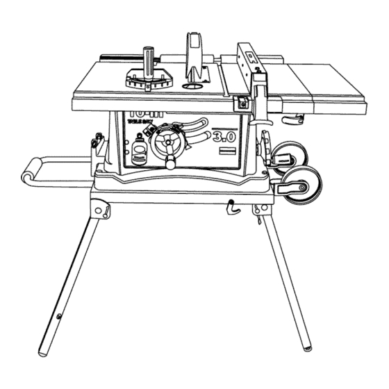
Operator's Manual
3.0 HP (Max. Developed)
10" Inch Blade
5000 R.P.M.
JOBSITE SAW
Model: 137.218240
CAUTION:
Before using this Table Saw,
read this manual and follow
all its Safety Rules and
Operating
Instructions
•
Safety Instructions
•
Installation
•
Operation
•
Maintenance
•
Parts List
Customer
Help Line
1-800-843-1682
Sears, Roebuck and Co., Hoffman Estates, IL 60179 USA
Visit our Craftsman website: www.sears.com/craftsman
Part No. : 137218240001
Advertisement

Related Manuals for Craftsman 137.218240


Summary of Contents for Craftsman 137.218240
- Page 1 • Operation all its Safety Rules and • Maintenance Operating Instructions • Parts List Customer Help Line 1-800-843-1682 Sears, Roebuck and Co., Hoffman Estates, IL 60179 USA Part No. : 137218240001 Visit our Craftsman website: www.sears.com/craftsman...
- Page 2 SECTION PAGE SECTION PAGE Know Your Table Saw ....... Warranty ........Product Specifications ....... Assembly and Adjustments ....Power Tool Safety ......Operation ........Maintenance ........Table Saw Safety ......Electrical Requirements and Safety ..Troubleshooting Guide ....... Accessories and Attachments ....Parts List ........
- Page 3 Before using your table saw, it is critical that you read and understand these safety rules. Failure to follow these rules could result in serious injury or damage to the table saw. Good safety practices are a combination of common accessories.
- Page 4 PROVIDE ADEQUATE SUPPORT to the rear and ALWAYS USE SAW BLADE GUARD, splitter and anti-kickback pawls for every operation for which they the sides of the saw table for long or wide can be used, including through-sawing. Through- workpieces. sawing operations are those in which the blade cuts completely through the workpiece when ripping or AVOID KICKBACKS (work thrown back towards...
- Page 5 POWER SUPPLY REQUIREMENTS GROUNDING INSTRUCTIONS IN THE EVENT OF A MALFUNCTION BREAKDOWN, grounding provides a path of least To avoid electrical hazards, fire hazards or damage to resistance for electric current and reduces the risk of the table saw, use proper circuit protection. Always electric shock.
- Page 6 • To order parts, call 1-800-366-7278 Visit your Sears Hardware Department or see the Craftsman Power and Hand Tools Catalog to purchase recommended accessories for this power tool. Separate all parts from packing materials. Check each part with the illustration on the next page and the "Table of Loose Parts"...
- Page 7 UNPACKING YOUR TABLE...
- Page 8 TheFrontof TableSaw Table insert Blade guard with LED lighting Rip fence Miter gauge Cutting line Side table indicator _xtension Bevel angle Pointer & scale Extension wing Overload reset locking lever switch ._----- Blade tilting Miter gauge handwheel storage Blade bevel Rip fence storacie lock knob...
- Page 9 STAND ASSEMBLY (Fig. A-l) flat washers onto four hex. head bolts (1) - (Fig. A-2). Place them through the base mounting holes and 1. Release the stand locking hook (1) by sliding it to the left. 2. Unfold the wider leg set on the left side of the stand (2). thread into the stand mounting and tighten all four bolts securely.
- Page 10 SAW MOUNTED TO WORK SURFACE (FIG. B) INSTALLING BATTERY FOR LED WORKLIGHT (FIG.D) 1. If the leg set will not be used, the saw must be 1. Open the cover (1) of the battery box on the top of blade properly secured to a sturdy workbench using the guard.
- Page 11 RIP FENCE (Fig. G) height by turning the blade raising handwheel counterclockwise. 1. Lift upward on the rip fence handle (1) so the rear clamp (2) is fully extended. 3. Place the open-end wrench jaws on the fiats of 2. Place the rip fence on the saw table by engaging the saw arbor to keep the arbor from turning.
- Page 12 BLADE GUARD ASgEMBLY [F_G K. U M _:_- ..• _ ..=,= .._...... 4 ;_:. °...
- Page 13 INSTALLING THE TABLE SIDE EXTENSIONS- cont'd ADJUSTING REAR TABLE EXTENSION (FIG O) Rear table extension should be positioned as close 6. Snap one location seat (5) over the end of the rear as possible to the rear of the table when ripping table extension tube (3).
- Page 14 RIP FENCE INDICATOR ADJUSTMENT (FIG. P) 45 ° Stop 1. The rip fence indicator (6) points to the With the blade in the upright 90 ° position, loosen measurement scale (8). The scale shows the the bevel lock knob and move the blade to the distance between the fence and the blade.
- Page 15 BLADE PARALLEL TO THE MITER GAUGE Additional blade adjustments (Fig. S) GROOVE (FIG. R,S) NOTE: The adjusting nuts are 8mm. The adjusting mechanism is located above the blade WARNING I height adjusting hand wheel under the tabletop. If the front and rear measurements are not the same, This adjustment was made at the factory, but it adjust the alignment by the mechanism as follows:...
- Page 16 BASIC SAW OPERATIONS OVERLOAD PROTECTION (FIG. V) This saw has a reset overload relay button (3) that ADJUSTING BLADE HEIGHT (FIG. T) will restart the motor after it shuts off due to To raise or lower the blade, turn the blade elevation overloading or low voltage, tf the motor stops during handwheel (1) to the desired blade height.
- Page 17 CUTTING OPERATIONS 5. Slowly feed the workpiece into the blade by pushing There are two basic types of cuts: ripping and forward only on the workpiece section (1) that will crosscutting. Ripping is cutting along the length and pass between the blade and the fence. (Fig. W) with the grain of the workpiece.
- Page 18 BEVEL RIPPING turning. Turn the switch OFF, and carefully slide the This cut is the same as ripped except the blade bevel )iece out when the blade is completely stopped. angle is set to an angle other than "0". Always position the larger surface of the workpiece on the table when crosscutting and/or bevel crosscutting to avoid Cut only with the workpiece and the fence on the right unstability.
- Page 19 MITERING (FIG. BB) 00-45 ° MITER ANGLE Fig. CC-1 This sawing operation is the same as crosscutting 30" except the miter gauge is locked at an angle other than 90 °. WARNING - Always work to the left side of _:"...
- Page 20 MAINTAINING YOUR TABLE SAW Fig. EE GENERAL MAINTENANCE For your own safety, turn the switch OFF and remove the switch key. Remove the plug from the power source outlet before maintaining or lubricating your saw. 1. Clean out all sawdust that has accumulated inside the saw cabinet and the motor.
- Page 21 To avoid injury from an accidental start, turn the switch OFF and always remove the plug from the power source before making any adjustments. • Consult your local Sears Service Center if for any reason the motor will not run. SYMPTOM POSSIBLE CAUSES CORRECTIVE ACTION...
- Page 22 10" JOB SITE TABLE Model : 137.218240 WARNING] When servicing use only CRAFTSMAN replacement parts. Use of any other parts many create a HAZARD or cause product damage. WARNING Any attempt to repair or replace electrical parts on this Table Saw may create a HAZARD unless repair is done by a qualified service technician.
- Page 23 • +-.+. £I...
- Page 24 10" JOB SITE TABLE Model : 137.218240 PARTS LIST FOR Schematic I.D. Description Size I.D. Description Size 2149 KNOB 0JVB HEX. SOC. HD. CAP BOLT M5x0.8-16 2759 BODY SHELL 0JXL HEX. SOC. SETSCREW M10x1.5-12 2771 ANGLE ROD 0KOZ HEX. HD. SCREW AND WASHER M8x1.25-16 08VH CLAMP-CORD...
- Page 25 Ok _X _ I",3 0i!4...
- Page 26 10" JOB SITE TABLE Model:137.218240 Part list for MOTOR I.D. No. Description Size 1502 FIELDASS'Y 0HX9 NEEDLE BEARING HK-1010 0JAL EXT.TOOTH LOCK WASHER 0JX3 HEX. SOC. SETSCREW M5x0.8-8 0K3A CR.RE. PAN HD. SCREW & WASHER M5x0.8-30 0K5V CR.-RE. COUND.HD.SCREW M4x0.7-8 0KCP CR.RE.
- Page 27 ORIY OR2 % (_C1 O(R) <. 1502 o ]S O,X[' Ok!\ OQ[} <)<\...
- Page 28 10" JOB SITE TABLE Model : 137.218240 Part list for STAND I.D. Description Size 2878 CLAMP HANDLE 0lAD WING NUT 01AE LEVELING PAD 0J4F FLAT WASHER (p8X16-2.5 0J58 FLAT WASHER (p5X14-1 0JAZ WAVE WASHER WW-6 0K7D CR. RE. ROUND WASHER HD. SCREW M6X1.0-10 0K7M CR.
- Page 29 10" JOB SITE TABLE Model : 137.218240 STAND...
- Page 30 PUSH STICK CONSTRUCTION • This is a full-size drawing (actual size) • Use good quality plywood or solid wood • Use ½" or ¾" material • Push stick MUST be thinner than the width of material being cut Notch To Prevent Hand From Slipping Cut Here To...