Table of Contents
Advertisement
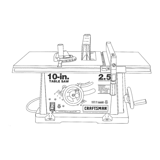
Owner's Manual
2.5 HP (Ma×imum
Deveioped)
10" inch Blade
5000 R.P.M.
TABLE SAW
ModeJ No.
!37.218780
CAUTION..
Before using this Table Saw,
read this manual and follow
all its Safety Rules and
Operating
Instructions.
o Safety Instructions
o Installation
,, Operation
• Maintenance
® Parts List
,, EspaSol
Customer
Help
Line
1-800-843-1682
Sears, Roebuck and Co., Hoffman
Estates,
mL60179 USA
Part No. 137218780001
Advertisement
Table of Contents

Related Manuals for Craftsman 137.218780


Summary of Contents for Craftsman 137.218780
- Page 1 Owner's Manual 2.5 HP (Ma×imum Deveioped) 10" inch Blade 5000 R.P.M. TABLE SAW ModeJ No. !37.218780 CAUTION.. o Safety Instructions o Installation Before using this Table Saw, read this manual and follow ,, Operation all its Safety Rules and • Maintenance Operating Instructions.
- Page 2 GENERAL SAFETY INSTRUCTIONS WEAN YOUR ALWAYS WEAR EYE PROTECTION. Any table SECTION PAGE BEFORE USING THE TABLE saw can throw foreign objects into the eyes which Warranty ..............Safety is a combination of common sense, staying alert could cause permanent eye Product Specifications .............
- Page 3 23. DIRECTION OF FEED. Feed work into a blade or cutter GROUNDING INSTRUCTIONS PROVIDE ADEQUATE SUPPORT to the rearand Fig. A against the direction of rotation of the blade or cutter sides of the saw table for wide or long Wbrkpiece_i IN THE EVENT OF A MALFUNCTmON OR BREAKDOWN, 3-Prong PIug...
- Page 4 Separate all parts from packing material. Check each one Visit your Sears Hardware Department or see the with the illustration on the next page and the table of Craftsman Power and Hand Tools Catalog to purchase loose parts to make certain all items are accounted for, recommended accessories for this power tool.
- Page 5 SAW MOUNTED TO WORK SURFACES (FIG. A) The saw must be properly secured to a sturdy Fig. B r_i:_ workbench using the four mounting holes at [he base of the saw. Blade guard The surface of the table where the saw is to be 31einsert mounted must have a hole large enough to facilitate Miter gauge...
- Page 6 RIP FENCE (FIG.E) Raise the btade arbor (4) (FIG. G) to the maximum BLADE GUARD ASSEMBLY (FIG. I, J, K, L) Che6k that the nuts (7) that hold the blade guard 1. Thread the fence handle (t) into the cam hole (2) height by turning the blade-raising handwheel assembly (8) to the bracket (4) are tight.
- Page 7 ADJUSTMENT INSTRUCTIONS BLADE PARALLEL TO MITER GAUGE Fig. N Loosen the bevel lock knob. Turn the blade tilting handwheel to move the blade until it is 90 ° to the GROOVE (FIG. Q, R) table. MITER GAUGE ADJUSTMENT (FIG. M) Adjust the collar (5) so it contacts the bracket (3) This adjustment was made at the factory, but it should Make sure that the miter gauge will slide freely through...
- Page 8 Additional blade adjustments (FIG. R) 1. If the front and rear measurements are not the To avoid injury, the ON/OFF switch should be in the OFF AVOID KICKBACK by pushing forward only on that same, remove the combination square and loosen the four adjusting screws (1) on the top of the table position and the plug removed from the power source section of the workpiece that will pass between the blade...
- Page 9 BEVEL RIPPING COMPOUND MITER CROSSCUTTING (FIG. Y) Fig. W This cut is the same as ripping except the blade bevel This sawing operation combines a miter angle with a angle is set to an angle other than 0 °. bevel angle. ,,, S Set the miter gauge (3) to the desired angle.
- Page 10 TROUBLESHOOTMNG GUIDE MAINTAINING YOUR TABLE Fig. CC GENERAL MAINTENANCE To avoid injury from an accidental start, turn the switch OFF and always remove the plug from the power source before making any adjustments. For your own safety, turn the switch OFF and remove the •...