Table of Contents
Advertisement
Operator's
Manual
®
10 in. TABLE SAW
Model No. 137.248840
CAUTION:
Before using this Table Saw,
read this manual and follow
all its Safety Rules and
Operating
Instructions
®
Safety Instructions
®
Installation
®
Operation
®
Maintenance
®
Parts List
Customer
Help Line
1 o800o843ol
682
Sears, Roebuck
and Co., Hoffman
Estates,
IL 60179 USA
Visit our Craftsman
website:
www.sears.com/craftsman
Part No. 137248840001
Advertisement
Table of Contents

Related Manuals for Craftsman 137.248840


Summary of Contents for Craftsman 137.248840
- Page 1 Operation read this manual and follow ® Maintenance all its Safety Rules and ® Parts List Operating Instructions Customer Help Line 1 o800o843ol Sears, Roebuck and Co., Hoffman Estates, IL 60179 USA Visit our Craftsman website: www.sears.com/craftsman Part No. 137248840001...
- Page 2 FULL WARRANTY ON CRAFTSMAN TOOL If this Craftsman tool fails due to a defect in material or workmanship within one year from the date of purchase, CALL 1-800-4-MY-HOME ®TO ARRANGE FOR FREE REPAIR. If this toot is used for commercial or rental purposes, this warranty wi!l apply for only ninety days from the date of purchase.
- Page 3 la, WARNING Before using your tabJe saw, it is critical that you read and understand these safety rules. Failure to follow these rules couJd result in serious injury or damage to the table saw. Good safety practices are a combination of common 16.
- Page 4 1. ALWAYS USESAWBLADEGUARD, splitter a nd functioning. Donotrelease workbeforeithas anti-kickback pawls foreveryoperation f orwhich passed a!lthewaypastthesawbladeandisoffthe theycanbeused, i ncluding through-sawing. table. D onotripworkthatistwisted, w arped or Through-sawing operations a rethoseinwhich the doesnothavea straight e dgetoguideitalongthe fence. bladecutscompletely t hrough theworkpiece w hen ripping orcross-cutting.
- Page 5 motor to the power line, make sure the switch is in the GROUND(NG (NSTRUCT(ONS off position and the e(ectric current is rated the same as the current stamped on the motor nameplate. Running IN THE EVENT OF A MALFUNCTION OR at a lower voltage wi(( damage the motor.
- Page 6 RECOMMENDED ACCESSORIES Separate all parts from packing materials. Check each part with the illustration on the next page and the "Table IA WARNING of Loose Parts" to make certain all items are accounted for, before discarding any packing material Visit your Scars Hardware Department or see the Scars Power and Hand TooJ Catalog to purchase WARNING...
- Page 7 UNPACKING YOUR TABLE ®®...
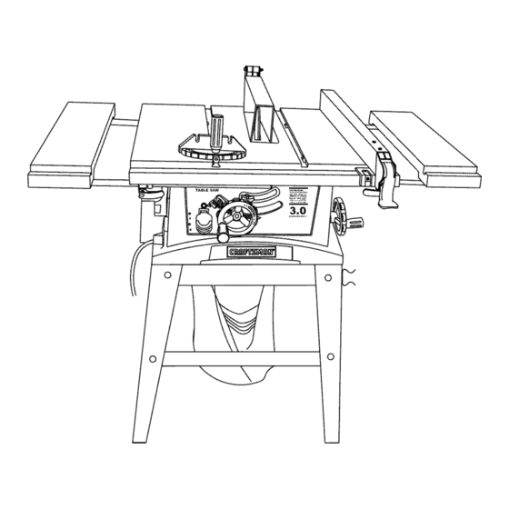
- Page 8 Table insert Blade Guard Rip Fence Side Table Extension Wing Extension Wing Locking Overload Reset Switch Blade Tilt Pointer & Scale Bevel Tilting Handwheel ON/OFF Switch with Saftey Key Blade Bevel Lock Knob Blade Elevation Handwheel Miter Gauge Table Rear Outfeed Table Extension Mounting Holes Stand Dust Bag...
- Page 9 ANTFKICKBACK P AWLS = Prevents t heworkpiece ON/OFF SWITCH = Contains a built-in safety switch key.TolocktheswitchintheOFFposition, remove the frombeingkicked upward or backtoward thefrontof the switchkeyfromtheswitch. tablesawbythespinning blade. OVERLOAD RESET SWITCH = Resets the ARBOR =Theshaftonwhichthebladeordadois mounted. thermocouple andprovides a wayto restart t hesaw motor ifit overloads o r overheats.
- Page 10 ASSEMBLE STAND (FIG. A ) ASSEMBLE TABLE SAW TO STAND (FIG. B) 1 Unpack allpartsandgroupbytypeandsize Refer 1 Place protective cardboard or old blanket on floor to totheparts!istforcorrect q uantities protect the saw table surface 2 Attach onelongupper support ( S)totopofleg(V) 2 Place the saw up side down on the protective using onebolt(1)andnut(2) materia! (see Fig B)
- Page 11 MOUNT SAWONWORK SURFACE (FIG.C) INSTALLING THE DUST BAG (FIG. D) 1. Ifthelegsetwillnotbeused,thesawmustbe WARNING] properly secured toa sturdyworkbench u sing the fourmounting holes at thebaseofthesaw. Do not use this saw to cut and/or sand metals. The 2. Thesurface ofthetablewhere thesawis tobe hot chips or sparks may ignite sawdust or the bag mounted m usthavea holelarge enough tofacilitate...
- Page 12 RIPFENCE (Fig,G) 4. Remove the arbor nut (5) and outer flange (6) (Fig. I). 1. Liftupward onthe ripfencehandle (1)sothe rear 5. install the saw blade onto the arbor with the BLADE holding clamp (2) TEETH POINTING TOWARD THE FRONT OF THE is fully extended.
- Page 13 BLADEGUARD ASSEMBLY (FIG.K, L, M) DANGER] 1. Setthebladetomaximum height a ndthetilttozero Improper splitter alignment can cause "kickback" degrees onthebevel s calewiththehandwheels. and serious injury. Lockthebladebevel l ockknob. 2. Place thespring washer (2),flatwasher (3),external Fig. M toothlockwasher (4)ontothebladeguardmounting bolt(1)(Fig.K). 3. Insert b oltandwasher a ssembly t hrough splitter Anti-Kickback Pa_I bracket ( 5).
- Page 14 iNSTALLiNG THE TABLE SIDE EXTENS!ONS- cont'd ADJUSTING REAR TABLE EXTENSION (FIG. O} 1. Rear table extension should be positioned as close 6. Snap one short location seat (1) over the end of the as possible to the rear of the table when ripping short rear table extension tube (2).
- Page 15 RiPFENCE iNDiCATOR ADJUSTMENT (FIG.Q) Fig. S 1_Theripfenceindicator ( 6)points tothemeasurement scale. T hescaleshows thedistance fromthesideof 9o° (0o) 45 ° thefencetonearest s ideoftheblade. 2_ Measure t heactual d istance witha rule.if there is a difference b etween the measurement andthe indicator, adjust the indicator (6)_ 3_ Loosen the screw (7) and slide the indicator to the correct measurement on the scale.
- Page 16 BLADEPARALLEL T OTHEMITER GAUGE GROOVE Additional blade adjustments (Fig. V) (FIG.U,V) NOTE: The adjusting nuts are 8ram. The adjusting mechanism is located above the blade I_WARNiNG height adjusting hand whee! under the tabletop. If the front and rear measurements are not the same. This adjustment was made at the factory, but it...
- Page 17 8ASmC SAW OPERATmONS OVERLOAD PROTECTION (FIG. X) This saw has an overload relay button (3) that resets RAISE THE BLADE (FIG. W) the motor after it shuts off due to overloading or low To raise or lower the blade, turn the blade elevation voltage.
- Page 18 CUTTING OPERATIONS 5. Slowly feed the workpiece into the blade by pushing Therearetwobasictypesofcuts:ripping and forward only on the workpiece section (1) that will crosscutting. Ripping is cutting alongthelength andthe pass between the blade and the fence. (Fig. AA) grainoftheworkpiece. Crosscutting is cutting either [,&WARNING] acrossthewidthor across thegrainoftheworkpiece.
- Page 19 REVEL RiPPiNG USING WOOD FACING ON THE MITER GAUGE Thiscutis thesameas ripping except t hebladebevel (Fig. RD) angle is set to an angle other than "0". Slots are provided in the miter gauge for attaching an auxiliary facing (1) to make it easier to cut very long or la, WARNING short pieces.
- Page 20 COMPOUND M ITER CROSSCUTTING (FIG.FF) USING WOOD FACING ON THE RIP FENCE 0°~45 ° BLADE BEVEL & 00~45 ° MITER ANGLE (FIG. HN} This sawing operation is combining a miter angle with o When performing some specio! cutting operations, odd bevel angle.
- Page 21 Attachauxiliary f enceto ripfencewithtwo"C"clamps. WARNING (Fig.dd) For your own safety, always replace the blade, blade guard assembly, and btade insert when you are Fig.JJ finished with the dado operation. You must atso realign the blade guard assembly. Fig. KK CUTS (FIG. KK) DADO IAWARNING n "_...
- Page 22 GENERAL MAINTENANCE Fig. LL IA WARNING For your own safety, turn the switch OFF and remove the switch kay. Remove the plug from the power source outlet before maintaining lubricating your saw. 1. Clean out al! sawdust that has accumulated inside the saw cabinet and the motor.
- Page 23 IAWARNmNG n To avoidinjury from an accidental start, turntheswitch"OFF" and always remove theplugfromthepower source before making any adjustments_ ® Consult your !ocal Sears Service Center if for any reason the motor wil! not run. SYMPTOM POSSIBLE CAUSES CORRECTIVE ACT!ON Saw will not starL Saw not plugged in.
- Page 24 TABLE MODEL NO. t37.248840 [A WAR.I.G [ When servicing use only CRAFTSMAN replacement parts. Use of any other parts many create a HAZARD or cause product damage. Any attempt to repair or replace electrical parts on this Table Saw may create...
- Page 25 10 in. TABLE MODEL NO. 137.248840 SCHEMATIC FOR SAW 0J76 0JAA _" IOGP OKAP OBCW 2 20KA 2179 09JK OB3R 0J76 OBPA 2CWN OBAE_ OKMR 0B99...
- Page 26 10 in. TABLE MODEL NO. 137.248840 PARTS LIST AND SCHEMATIC FOR STAND I.D. NO DescripJJon Size 09D6 FOOT PAD 0A4T FENCE STORAGE CLiP 0EAA BRACKET 0EAN UPPER SUPPORT 0EAP UPPER SUPPORT 0EAY UPPER SUPPORT 0EBB BOTTOM SUPPORT BRACKET 0EBG BOTTOM SUPPORT BRACKET 0J4F FLAT WASHER (pSX16=2_5...
- Page 27 10 in. TABLE MODEL NO. 137.248840 PARTS LIST AND SCHEMATIC FOR MOTOR Size i.D. NO Descdp_ion 0HV8 BALL BEARING 6201ZLU 0HVU BALL BEARING 6200ZZ 0HXg NEEDLE BEARING 0JAL EXT.TOOTH LOCK WASHER 0JX3 HEX. SOC. SETSCREW M5'0.8-8 0K3A CR,RE. PAN HD. SCREW & WASHER M5_,0.8-30 0KSV CR,-RE.
- Page 28 PUSH STICK CONSTRUCTION ® This is a full°size drawing (actual size) ® Use good quality plywood or sotid wood ® Use %" or ¾" material Push stick MUST be thinner than the width of materiat being cut Jotch To Prevent Hand From Slipping Cut Here To...
- Page 30 Your Home For repair - in your home - of all major brand appliances, lawn and garden equipment, or heating and cooling systems, no matter who made it, no matter who soJd it! For the replacement parts, accessories Operator's Manuals that you need to do-it-yourself. For Sears professional installation of home appliances...