Table of Contents
Advertisement
Quick Links
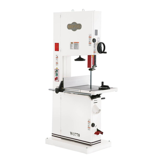
MODEL W1770
21" BANDSAW
w/FOOt BRAkE
OWNER'S MANUAL
Phone: (360) 734-3482 • Online technical Support: tech-support@shopfox.biz
COPYRIGHt © SEPtEMBER, 2008 BY WOODStOCk INtERNAtIONAL, INC.
WARNING: NO PORtION OF tHIS MANUAL MAY BE REPRODUCED IN ANY SHAPE OR FORM WItHOUt
tHE WRIttEN APPROVAL OF WOODStOCk INtERNAtIONAL, INC.
Printed in taiwan
#11150BL
Advertisement
Table of Contents

Related Manuals for Shop fox SHOP FOX W1770


Summary of Contents for Shop fox SHOP FOX W1770
- Page 1 MODEL W1770 21" BANDSAW w/FOOt BRAkE OWNER'S MANUAL Phone: (360) 734-3482 • Online technical Support: tech-support@shopfox.biz COPYRIGHt © SEPtEMBER, 2008 BY WOODStOCk INtERNAtIONAL, INC. WARNING: NO PORtION OF tHIS MANUAL MAY BE REPRODUCED IN ANY SHAPE OR FORM WItHOUt tHE WRIttEN APPROVAL OF WOODStOCk INtERNAtIONAL, INC. Printed in taiwan #11150BL...
- Page 2 This manual provides critical safety instructions on the proper setup, operation, maintenance, and service of this machine/tool. Save this document, refer to it often, and use it to instruct other operators. Failure to read, understand and follow the instructions in this manual may result in fire or serious personal injury—including amputation, electrocution, or death.
-
Page 3: Table Of Contents
Contents INTRODUCTION........2 OPERATIONS........31 Woodstock Technical Support ....2 General .......... 31 Functional Overview ......2 Basic Controls ........31 SAFETY..........6 Workpiece Inspection ......33 Standard Machinery Safety ..... 6 Cutting Overview ....... 34 Additional Safety for Bandsaws ....8 Foot Brake ........ -
Page 4: Introduction
Woodstock International, Inc. is committed to customer satisfaction. Our intent with this manual is to include the basic information for safety, setup, operation, maintenance, and service of this product. - Page 5 W1770 21" Bandsaw w/Foot Brake MODEL W1770 SHOP FOX 21" BANDSAW 5HP, SINGLE PHASE ® Product Dimensions Weight......................594 lbs. Width (side-to-side) x Depth (front-to-back) x Height......39-1/2 x 28-5/8 x 78 in. Footprint (Length x Width)..............21-5/8 x 33-1/2 in. Shipping Dimensions Type....................
- Page 6 W1770 21" Bandsaw w/Foot Brake Main Specifications Main Specifications Bandsaw Size....................21 in. Max Cutting Width (Left of Blade)..............20 in. Max Cutting Width (Left of Blade) w/Fence............ 18-3/4 in. Max Cutting Height (Resaw Height).............. 14-1/4 in. Blade Speeds..................4600 FPM Blade Information Standard Blade Length.................
- Page 7 W1770 21" Bandsaw w/Foot Brake Controls.and.Features Figure.1. W1770 front features. Figure.2. W1770 rear features. A.. Eye Bolt N. Resaw Fence B.. Hinged Wheel Cover O. Blade Tension Scale C.. Blade Tracking Window P. Blade Tracking Lock Lever D. Guide Post Handwheel Q.
-
Page 8: Safety
W1770 21" Bandsaw w/Foot Brake SAFETY SAFETY READ MANUAL BEFORE OPERATING MACHINE. FAILURE TO FOLLOW INSTRUCTIONS BELOW WILL RESULT IN PERSONAL INJURY. Indicates an imminently hazardous situation which, if not avoided, WILL result in death or serious injury. Indicates a potentially hazardous situation which, if not avoided, COULD result in death or serious injury. - Page 9 W1770 21" Bandsaw w/Foot Brake 10. NEVER LEAVE WHEN MACHINE IS RUNNING. Turn power OFF and allow all moving parts to come to a complete stop before leaving machine unattended. 11. DO NOT USE IN DANGEROUS ENVIRONMENTS. DO NOT use machinery in damp, wet locations, or where any flammable or noxious fumes may exist.
-
Page 10: Additional Safety For Bandsaws
W1770 21" Bandsaw w/Foot Brake Additional.Safety.for.Bandsaws Like.all.machinery.there.is.potential.danger.when.operating.this.bandsaw..Accidents.are.frequently. caused.by.lack.of.familiarity.or.failure.to.pay.attention..Use.this.mill.with.respect.and.caution.to. reduce.the.risk.of.operator.injury..If.normal.safety.precautions.are.overlooked.or.ignored,.serious. personal.injury.may.occur. 1.. BLADE.CONDITION. Do not operate with dull, cracked or badly worn blade. Dull blades require more effort to use and are difficult to control. Inspect blades for cracks and missing teeth before each use. -
Page 11: Avoiding Potential Injuries
W1770 21" Bandsaw w/Foot Brake Avoiding.Potential.Injuries Figure.3. Never place hands in line of cut. Figure.4. Use push blocks when necessary. Figure.6. Use push sticks whenever possible. Figure.5..Never start motor with wheel covers Figure.7..Unplug saw before changing blades. open. -
Page 12: Electrical
W1770 21" Bandsaw w/Foot Brake ELECTRICAL L6-30 GROUNDED LOCKING RECEPTACLE The. machine. must. be. properly. set. up. before. it. is. safe.to.operate..DO.NOT.connect.this.machine.to.the. Grounding Prong power. source. until. instructed. to. do. so. in. the. "Test. is Hooked Run".portion.of.this.manual. L6-30 LOCKING PLUG 220V.Operation Current Carrying Prongs The Model W1770 is wired for 220V single-phase opera- Figure.8. -
Page 13: Setup
W1770 21" Bandsaw w/Foot Brake SETUP Unpacking This machine has been carefully packaged for safe trans- portation. If you notice the machine has been damaged during shipping, please contact your authorized Shop Fox dealer immediately. Items.Needed.for.Setup Keep. machine. disconnected. from. The following items are needed to complete the setup power.until.instructed.otherwise. -
Page 14: Inventory
W1770 21" Bandsaw w/Foot Brake Inventory The following is a description of the main components shipped with the Model W1770. Lay the components out to inventory them. Note: If you can't find an item on this list, check the mounting location on the machine or examine the pack- aging materials carefully. -
Page 15: Machine Placement
W1770 21" Bandsaw w/Foot Brake Machine.Placement Cleaning.Machine •. Floor.Load: This machine distributes a The table and other unpainted parts of your heavy load in a small footprint. Some bandsaw are coated with a waxy grease that protects them from corrosion during shipment. residential floors may require additional Clean this grease off with a solvent cleaner or bracing to support both machine and... -
Page 16: Lifting & Moving
W1770 21" Bandsaw w/Foot Brake Lifting.&.Moving Eye Bolt This.is.an.extremely.heavy.machine..Serious.personal. injury.may.occur.if.safe.moving.methods.are.not.fol- lowed..To.be.safe,.you.will.need.assistance.and.a.fork- lift. or. a. hoist. when. removing. the. machine. from. the. crate..Use.a.chain.or.a.lifting.strap.with.a.minimum.of. 1000.lbs..lifting.capacity..If.the.chain.or.lifting.strap. breaks,.serious.personal.injury.may.occur. Take special care when moving this bandsaw. Only use one of the following methods to lift or move this bandsaw. To.move.and.place.the.bandsaw.using.the.eye.bolts,.do. -
Page 17: Mounting To Shop Floor
W1770 21" Bandsaw w/Foot Brake Mounting.to.Shop.Floor Although not required, we recommend that you mount your new bandsaw to the floor. Because this is an optional step and floor materials may vary, floor mounting hard- ware is not included. You must use a precison level to level your machine. -
Page 18: Fence
W1770 21" Bandsaw w/Foot Brake Fence The fence rail is installed upside down at the factory. To.install.the.fence,.do.these.steps: 1. Remove the cap screws holding the rail onto the table, and remove the rail. 2.. Flip the rail over and reinstall it with the cap screws removed in Step.1.(see Figure.14). -
Page 19: Blade Tracking
W1770 21" Bandsaw w/Foot Brake Blade.Tracking The blade tracking is primarily affected by the tilt of the upper wheel, also known as "center tracking"; and the Blade alignment of both wheels, also known as "coplanar track- Tension ing." (For coplanar tracking, refer to the Wheel.Alignment Scale instructions on.Page.52.) Blade Tension... -
Page 20: Positive Stop
W1770 21" Bandsaw w/Foot Brake Positive.Stop The positive stop allows the table to be quickly and accu- rately returned to the horizontal (0˚) position after being adjusted to a different angle. To set the positive stop, do these steps: Stop Bolt 1.. -
Page 21: Dust Collection
W1770 21" Bandsaw w/Foot Brake Dust.Collection Recommended.CFM.at.each.Dust.Port:..400.CFM Do not confuse this CFM recommendation with the rating of the dust collector. To determine the CFM at the dust port, you must take into account many variables, includ- ing the CFM rating of the dust collector, the length of hose between the dust collector and the machine, the amount of branches or Y's, and the amount of other open lines throughout the system. -
Page 22: Test Run
W1770 21" Bandsaw w/Foot Brake Test.Run Once the assembly is complete, test run your machine to make sure it runs properly and is ready for regular opera- tion. The test run consists of verifying the following: 1) The motor powers up and runs correctly, and 2) the safety disabling mechanism on the switch works correctly, and 3) the OFF button safety feature works correctly. - Page 23 W1770 21" Bandsaw w/Foot Brake — If the machine does start (with the stop button pushed in), immediately disconnect power to the machine. The OFF button safety feature is not working correctly. This safety feature must work properly before proceeding with regular opera- tions.
-
Page 24: Tensioning Blade
W1770 21" Bandsaw w/Foot Brake Tensioning.Blade A properly tensioned blade is essential for making accu- rate cuts and is required before making many bandsaw adjustments. (Everytime you replace the blade, you should perform this procedure because all blades tension differently.) To tension the bandsaw blade, do these steps: 1. -
Page 25: Adjusting Blade Guide Bearings
W1770 21" Bandsaw w/Foot Brake Adjusting.Blade.Guide. Bearings The blade guides provide side-to-side support to keep Guide Block the blade straight while cutting. The blade guides are Assembly Cap designed to be adjusted in two ways—forward/backward Blade Guide Screws and side-to-side. Bearings To adjust the upper blade guides, do these steps: 1. -
Page 26: Adjusting Support Bearings
W1770 21" Bandsaw w/Foot Brake NOTICE Blade Guide Bearings Whenever.changing.a.blade.or.adjusting.tension.and. tracking,.the.upper.and.lower.blade.support.bear- ings.and.guide.bearings.must.be.properly.adjusted. and.locked.before.cutting.operations.. To.adjust.the.lower.blade.guides,.do.these.steps: 1. Make sure the blade is tracking properly and that it Knurled is correctly tensioned. Knob Bearing Rotation 2. DISCONNECT BANDSAW FROM POWER! Adjustment Bolt Figure 30. Lower blade guide controls 3. - Page 27 W1770 21" Bandsaw w/Foot Brake 3. Familiarize yourself with the upper support bearing controls shown in Figures 27 & 28 on Page.23. Bandsaw Blade 4. Loosen the guide block assembly cap screws and Support rotate the blade guide assembly side-to-side, until Bearing the blade is perpendicular with the face of the sup- port bearing, as illustrated in Figure 32.
- Page 28 W1770 21" Bandsaw w/Foot Brake To.adjust.the.lower.support.bearing,.do.these.steps: Support Bearing 1. Make sure the blade is tracking properly and is cor- Adjustment rectly tensioned. Shaft Bolt 2. DISCONNECT BANDSAW FROM POWER! 3. Familiarize yourself with the lower support bearing controls shown in Figure.35. 4.
-
Page 29: Aligning Table
W1770 21" Bandsaw w/Foot Brake Aligning.Table To ensure cutting accuracy, the table should be aligned so that the miter slot is parallel to the bandsaw blade. This procedure works best with a 1 ⁄ " blade installed. To.align.the.table.so.the.miter.slot.is.parallel.to.the. bandsaw.blade,.do.these.steps: 1. Make sure that the blade is tracking properly and that it is correctly tensioned. -
Page 30: Aligning Fence
W1770 21" Bandsaw w/Foot Brake Aligning.Fence To ensure cutting accuracy when the fence is first installed, the fence should be aligned with the miter slot. To.align.the.fence.parallel.with.the.miter.slot,.do.these. steps: 1.. DISCONNECT BANDSAW FROM POWER! 2. Make sure the miter slot is aligned with the bandsaw blade (see Page.27). -
Page 31: Calibrating Fence Pointer
W1770 21" Bandsaw w/Foot Brake Calibrating.Fence.Pointer Your new bandsaw is equipped with a fence measurement system that includes a fence pointer, which must be cali- brated when the bandsaw is first set up. To.calibrate.the.pointer,.do.these.steps: 1.. If the fence is mounted on the right-hand side of the blade, remove it and re-install it on the left-hand side of the blade. -
Page 32: Installing Resaw Fence
W1770 21" Bandsaw w/Foot Brake Installing.Resaw.Fence To.install.the.resaw.fence,.do.these.steps: Resaw Fence Resaw Lock 1. Install the resaw fence lock handle (with the washer Handle and moving plate) onto the fence, then slide the resaw fence over the moving plate, as shown in Figure.43. -
Page 33: Operations
W1770 21" Bandsaw w/Foot Brake OPERATIONS General This machine will perform many types of operations that are beyond the scope of this manual. Many of these operations can be dangerous or deadly if performed incor- rectly. The instructions in this section are written with the under- standing that the operator has the necessary knowledge and skills to operate this machine. - Page 34 W1770 21" Bandsaw w/Foot Brake Front Controls (Figure.46) A. Blade.Tension.Scale: Allows for easy monitoring of blade tension. B. Blade.Tension.Handwheel: Tensions blade in gradual increments. C. Blade.Tracking.Window: Allows for easy monitoring of blade tracking (refer to Page.36). D. Fence,.Rails,.and.Miter.Gauge: Allows for controlled cutting at various angles.
-
Page 35: Workpiece Inspection
W1770 21" Bandsaw w/Foot Brake Workpiece.Inspection Some wood workpieces are not safe to cut or may require modification before they are safe to cut. Before.cutting.wood,.get.in.the.habit.of.inspecting.all. workpieces.for.the.following: •. Foreign.Objects.(Figure.48):.Nails, staples, dirt, rocks and other foreign objects are often embedded in wood. While cutting, these objects can become dislodged and hit the operator or break the blade, which might then fly apart. -
Page 36: Cutting Overview
W1770 21" Bandsaw w/Foot Brake Cutting.Overview The.bandsaw.is.capable.of.performing.the.following. cuts: • Miters • Crosscutting • Angles • Simple and Complex Curves • Compound Angles • Duplicate Parts • Resawing • Circles • Ripping • Beveled Curves Basic.Cutting.Tips • Keep the upper blade guide assembly adjusted to within 1"... -
Page 37: Foot Brake
W1770 21" Bandsaw w/Foot Brake Foot.Brake The Model W1770 is equipped with a foot brake (Figure. 50). Use the brake to cut power to the motor and bring the blade to a halt. NOTICE The. foot. brake. will. not. stop. the. bandsaw. wheels. and.blade.instantly..DO.NOT.become.over.confident. -
Page 38: Fine Tune Tracking
W1770 21" Bandsaw w/Foot Brake Fine.Tune.Tracking NOTICE Adjusting. the. final. blade. tracking. setting. requires. the.machine.to.be.turned.ON. To fine tune the tracking, do these steps: 1. Close the wheel covers and turn the bandsaw ON. 2. Observe the blade tracking path through the clear window on the right edge of the bandsaw, as shown in Figure.52. - Page 39 W1770 21" Bandsaw w/Foot Brake 2. Slide the bandsaw fence out of the way and cut half- way through the board on the line by pushing it into the blade. Turn the bandsaw OFF and wait for the blade to stop. 3.
-
Page 40: Table Tilt
W1770 21" Bandsaw w/Foot Brake Table.Tilt To.tilt.the.table,.do.these.steps: Table Tilt Handwheel 1.. DISCONNECT BANDSAW FROM POWER! 2. Loosen the table tilt lock lever shown in Figure.54. 3. To tilt the table to the right, turn the table tilt handwheel clockwise (Figure.54). Lock Lever 4. -
Page 41: Crosscutting
W1770 21" Bandsaw w/Foot Brake Crosscutting "Crosscutting" means cutting across the grain of wood. For plywood and other processed wood, crosscutting simply means cutting across the width of the material. To.make.a.90˚.crosscut,.do.these.steps: 1. Move the fence out of the way, adjust the blade guide assembly to less than 1"... -
Page 42: Cutting Curves
W1770 21" Bandsaw w/Foot Brake Cutting.Curves When cutting curves, simultaneously feed and turn the The.list.below.shows.the.minimum. stock carefully so the blade follows the layout line with- radius.that.can.be.cut.by.common. out twisting. If a curve is so abrupt that it is necessary to blade.widths. repeatedly back up and cut a new kerf, use a narrower blade (refer to FIgure.58), a blade with more TPI (teeth Width. - Page 43 W1770 21" Bandsaw w/Foot Brake Blade.Length Measured by the circumference, blade lengths are usually unique to the brand of your bandsaw and the distance between wheels. This saw uses 165" long blades. Blade.Width Measured from the back of the blade to the tip of the blade tooth (the widest point), blade width is often the first consideration given to blade selection.
- Page 44 W1770 21" Bandsaw w/Foot Brake Tooth.Pitch Usually measured as TPI (teeth per inch), tooth pitch determines the size/number of the teeth. More teeth per inch (fine pitch) will cut slower, but smoother; while fewer teeth per inch (coarse pitch) will cut rougher, but faster.
-
Page 45: Blade Changes
W1770 21" Bandsaw w/Foot Brake Blade.Changes To.remove.a.blade,.do.these.steps: 1. DISCONNECT BANDSAW FROM POWER! 2. Release the blade tension. 3. Remove the table insert and the table pin. Adjust the upper and lower guide bearings as far away as possible from the blade. Always.disconnect.power.to.the. -
Page 46: Maintenance
W1770 21" Bandsaw w/Foot Brake MAINTENANCE General For optimum performance from your machine, follow this maintenance schedule: Daily • Check/correct loose mounting bolts. • Check/correct damaged saw blade. • Check/correct worn or damaged wires. • Correct any other unsafe condition. Monthly MAKE. -
Page 47: Tension Adjustment Assembly
W1770 21" Bandsaw w/Foot Brake Blade Guide Rack and Pinion Lubricant Frequency Quantity Multi-Purpose As Needed Thin Coat GL2 Grease To.lubricate.the.blade.guide.rack.and.pinion,.do.these. steps: 1. DISCONNECT BANDSAW FROM POWER! 2. Lower the blade guide until it reaches the table. 3. Using a rag and mineral spirits, wipe off any existing grease and sawdust buildup on the rack (see Figure. - Page 48 W1770 21" Bandsaw w/Foot Brake Table Tilt Rack and Pinion Assembly Lubricant Frequency Quantity Multi-Purpose As Needed Thin Coat GL2 Grease To.lubricate.the.table.tilt.rack.and.pinion.assembly,.do. these.steps: 1.. DISCONNECT BANDSAW FROM POWER! 2. With the table perpendicular to the blade, and using a rag and mineral spirits, wipe off all existing grease and sawdust buildup from the rack.
-
Page 49: Service
If you require additional machine service not included in this section, please contact Woodstock International Technical Support at (360) 734-3482 or send e-mail to: tech-support@shopfox.biz. Checking.and.Tensioning. - Page 50 W1770 21" Bandsaw w/Foot Brake Tensioning.V-Belts 1. Follow Steps.1-2 in Checking.V-Belts on Page.47. 2. Loosen the motor adjustment screws shown in Tension Nut Figure.68. Tension Bolt 3. Adjust the belt tension: — If the belt is too loose, turn the tension nut clock- wise to tighten the belts.
-
Page 51: Adjusting Tension Lever
W1770 21" Bandsaw w/Foot Brake Adjusting.Tension.Lever The quick release tension lever is setup correctly for use with the preinstalled 165" blade. However, if you install a different length blade, you will need to adjust the tension Tension lever adjustment screw so the quick release tension lever Adjustment works correctly. -
Page 52: Adjusting Wheel And Blade Brushes
W1770 21" Bandsaw w/Foot Brake Adjusting.Wheel.and. Blade.Brushes The lower wheel compartment contains the brushes shown in Figure 71. These brushes are designed to sweep sawdust off the wheel tire and blade as the bandsaw is operating. In order to work properly, the brushes must be making contact with the wheel and blade. -
Page 53: Replacing Brake Shoe
The bandsaw takes noticeably longer to stop when the foot brake is pushed or the foot brake makes metal-to-metal grinding sounds. Brake Shoe Contact Woodstock International Technical Support at (360) 734-3482 to order the replacement brake shoe, Part X1770536 (refer to Page.64). Components.and.Hardware.Needed: Cap Screws Replacement Brake Shoe (Part X1770536) ....1... -
Page 54: Aligning Wheels
W1770 21" Bandsaw w/Foot Brake Aligning.Wheels Components.and.Hardware.Needed:. 4" ⁄ " Long Wood 2x4 ..........1 Tools.Needed: Wrench 17mm ...........1 Tape Measure ............1 Coplanarity Gauge (see Figure.73) ......1 21" Straightedge .............1 Fine Ruler ............1 Wheel alignment is one of the most critical factors for optimal performance from your bandsaw. - Page 55 W1770 21" Bandsaw w/Foot Brake —.If the wheels are coplanar (Figure.75, A), the straightedge will evenly touch the top and bottom of both wheels. —.If the wheels are not coplanar (Figure.75, B), Not Coplanar Coplanar place the straightedge on the lower wheel first (ensuring that it touches both the top and bottom Solution: rim), then adjust the upper wheel tracking knob to...
- Page 56 W1770 21" Bandsaw w/Foot Brake Adjusting.Lower.Wheel Only do this procedure if you cannot make the wheels coplanar with the tracking knob or by shimming the upper Top Tilt wheel. Make sure the upper wheel is adjusted as close as Jam Nut possible to being coplanar with the lower wheel before beginning.
-
Page 57: Electrical Components
W1770 21" Bandsaw w/Foot Brake Electrical.Components Figure.78. Power supply terminal box. Figure.81. Motor wiring. POWER Figure.79. Control panel wiring. Figure.80. Wheel cover limit switch (left) and Figure.82. Magnetic switch. foot brake switch (right). -55-... -
Page 58: Wiring Diagram
W1770 21" Bandsaw w/Foot Brake Wiring.Diagram SHOCK HAZARD! Disconnect power before servicing electrical parts. Touching electrified parts will result in POWER severe burns, electrocution, or death. SUPPLY JUNCTION Ground BLOCK (Figure 78, Page 55) 220 VAC L6-30 PLUG (as recommended) SWITCH LIMIT SWITCH (NC) ASSEMBLY... -
Page 59: Troubleshooting
W1770 21" Bandsaw w/Foot Brake Troubleshooting This section covers the most common problems and corrections with this type of machine. WARNING!.DO.NOT.make.any.adjustments.until.power.is.disconnected.and. moving.parts.have.come.to.a.complete.stop! Motor.&.Electrical PROBLEM POSSIBLE.CAUSE CORRECTIVE.ACTION Machine does not start or a 1. Key is turned to "0". 1. Turn key to "1". 2. - Page 60 W1770 21" Bandsaw w/Foot Brake Machine.Operations PROBLEM POSSIBLE.CAUSE CORRECTIVE.ACTION Machine slows when oper- 1. Feeding workpiece too fast. 1. Reduce feed rate. See Basic Cutting Tips on Page ating. 2. Blade is dull. 2. Replace/sharpen blade (Page 43). 3. Brake is stuck or dragging on 3.
-
Page 61: Parts
Labels.&.Cosmetic.Parts Safety. labels. warn. about. machine. hazards. and. how. to. prevent. machine. damage. or. injury.. The. owner. of. this. machine. MUST. maintain. the. original. location. and. readability. of. all. labels. on. this. machine..If.any.label.is.removed.or.becomes.unreadable,.REPLACE.that.label.before.allowing.the. machine.to.enter.service.again..Contact.Woodstock.International,.Inc..at.(360).734-3482.or.www. shopfoxtools.com.to.order.new.labels.. REF PART # DESCRIPTION REF PART #... -
Page 62: Blade Guides-Cover Breakdown
W1770 21" Bandsaw w/Foot Brake Blade.Guides-Cover.Breakdown 175 176 173 174 177 161 REF PART # DESCRIPTION REF PART # DESCRIPTION XPSB04M CAP SCREW M6-1 X 10 X1770162 UPPER SPACING SLEEVE XPLW03M LOCK WASHER 6MM XP6201ZZ BALL BEARING 6201ZZ XPW03M FLAT WASHER 6MM XPR03M EXT RETAINING RING 12MM X1770150... -
Page 63: Guide Post-Table Tilt Breakdown
W1770 21" Bandsaw w/Foot Brake Guide.Post-Table.Tilt.Breakdown 339 338 342 341 PART # DESCRIPTION PART # DESCRIPTION XPW03M FLAT WASHER 6MM X1770316 SUPPORT PLATE XPN06M HEX NUT M5-.8 XPW01M FLAT WASHER 8MM XPFS07M FLANGE SCREW M5-.8 X 10 XPSBS22M BUTTON HD CAP SCR M8-1.25 X 20 X1770287 COVER XPSB04M... -
Page 64: Table-Trunnion Breakdown
W1770 21" Bandsaw w/Foot Brake Table-Trunnion.Breakdown 484-10 484-7 484-12 484-8 484-13 484-11 484-9 484-5 484-3 484-2 484-6 484-4 484-10 PART # DESCRIPTION PART # DESCRIPTION X1770447 NYLON PIECE XPW04M FLAT WASHER 10MM X1770455 FENCE X1770477 TRUNNION BLOCK X1770456 KNOB SCREW M10-1.5 X 25 X1770478 PRESS BLOCK X1770457... -
Page 65: Body Breakdown
W1770 21" Bandsaw w/Foot Brake Body.Breakdown -63-... - Page 66 W1770 21" Bandsaw w/Foot Brake Body.Parts.List REF PART # DESCRIPTION REF PART # DESCRIPTION X1770501 HANDLE KNOB M16-1.5 XPHTEK4M TAP SCREW M4 X 8 X1770502 HANDLE SHAFT X1770547 CORD CLAMP 5/8” X1770503 NUT M16-1.5 X1770548 STEP CORD 16AWG X 3C X1770504 ECCENTRIC SHAFT XPB41M...
- Page 67 W1770 21" Bandsaw w/Foot Brake Body.Parts.List.Continued PART # DESCRIPTION PART # DESCRIPTION X1770593 MOTOR CORD 12AWG X 3C X1770629 BALL BEARING 6205LLU XPLN03M LOCK NUT M6-1 X1770630 LOWER WHEEL DIA. 21” XPN02M HEX NUT M10-1.5 X1770631 BUSHING XPW04M FLAT WASHER 10MM XPR26M INT RETAINING RING 52MM X1770597...
-
Page 68: Resaw Fence Breakdown
W1770 21" Bandsaw w/Foot Brake Resaw.Fence.Breakdown REF PART # DESCRIPTION REF PART # DESCRIPTION X1770801 RESAW FENCE (AL) 590MM X1770804 ADJUSTMENT HANDLE M8 X 44 X1770802 MOVING PLATE X1770810 END COVER 148 X 22 X 1 XPW01M FLAT WASHER 8MM XPHTEK3M TAP SCREW M3.5 X 8 -66-... - Page 69 W1770 21" Bandsaw w/Foot Brake Warranty.Registration Name ___________________________________________________________________________________ Street __________________________________________________________________________________ City _________________________ State ___________________________Zip ________________________ Phone # ______________________ Email___________________________Invoice # ___________________ Model #_________Serial #______________Dealer Name__________________Purchase Date___________ The following information is given on a voluntary basis. It will be used for marketing purposes to help us develop better products and services.
- Page 70 FOLD ALONG DOTTED LINE Place Stamp Here WOODSTOCK.INTERNATIONAL.INC.. P.O..BOX.2309. BELLINGHAM,.WA.98227-2309 FOLD ALONG DOTTED LINE TAPE ALONG EDGES--PLEASE DO NOT STAPLE...
-
Page 71: Warranty
Woodstock International, Inc. will repair or replace, at its expense and at its option, the Shop Fox machine or machine part, which in normal use has proven to be defective, provided that the original owner returns the product prepaid to a Shop Fox factory service center with proof of their purchase of the product within two years, and provides Woodstock International, Inc.