Table of Contents
Advertisement
Quick Links
Advertisement
Table of Contents
Troubleshooting

Related Manuals for Enterasys 5H102-48


Summary of Contents for Enterasys 5H102-48
- Page 1 5H102-48 and 5H103-48 Fast Ethernet Installation Guide 9033586...
- Page 3 Enterasys Networks and its licensors reserve the right to make changes in specifications and other information contained in this document without prior notice. The reader should in all cases consult Enterasys Networks to determine whether any such changes have been made.
-
Page 4: Fcc Notice
FCC NOTICE This device complies with Part 15 of the FCC rules. Operation is subject to the following two conditions: (1) this device may not cause harmful interference, and (2) this device must accept any interference received, including interference that may cause undesired operation. - Page 5 BEFORE OPENING OR UTILIZING THE ENCLOSED PRODUCT, CAREFULLY READ THIS LICENSE AGREEMENT. This document is an agreement (“Agreement”) between You, the end user, and Enterasys Networks, Inc. (“Enterasys”) that sets forth your rights and obligations with respect to the Enterasys software program (“Program”) in the package.
- Page 6 UNITED STATES GOVERNMENT RESTRICTED RIGHTS. The enclosed Product (i) was developed solely at private expense; (ii) contains “restricted computer software” submitted with restricted rights in accordance with section 52.227-19 (a) through (d) of the Commercial Computer Software-Restricted Rights Clause and its successors, and (iii) in all respects is proprietary data belonging to Enterasys and/or its suppliers.
-
Page 7: Declaration Of Conformity
DECLARATION OF CONFORMITY Application of Council Directive(s): 89/336/EEC Manufacturer’s Name: Enterasys Networks, Inc. Manufacturer’s Address: European Representative Name: Mr. Jim Sims European Representative Address: Conformance to Directive(s)/Product Standards: Equipment Type/Environment: Networking Equipment, for use in a Commercial We the undersigned, hereby declare, under our sole responsibility, that the equipment packaged with this notice conforms to the above directives. -
Page 9: Table Of Contents
Figures ...ix Tables... x ABOUT THIS GUIDE Using This Guide...xi Structure of This Guide ...xi Related Documents...xii Document Conventions... xiii Getting Help ...xiv INTRODUCTION Connectivity... 1-3 Half-Duplex/Full-Duplex Auto-Negotiation ... 1-3 Port Trunking... 1-3 Remote Monitoring (RMON) ... 1-3 Port/VLAN Redirect Function ... 1-4 Flow Control ... - Page 10 Environmental Requirements...A-1 Input/Output Ports ...A-2 COM Port Pinout Assignments ...A-2 Regulatory Compliance...A-3 MODE SWITCH BANK SETTINGS AND OPTIONS Required Tools...B-1 Setting the Mode Switches...B-2 INDEX viii Connecting UTP Cables to the 5H102-48... 3-5 Connecting UTP Cables to the 5H103-48... 3-8...
-
Page 11: Figures
Figure The 5H102-48 and 5H103-48 Modules ... 1-2 Installing a Module into the 5C105 Chassis ... 3-4 Connecting a Twisted Pair Segment to the 5H102-48 ... 3-6 Crossover Cable RJ45 Pinouts ... 3-7 Straight-Through Cable RJ45 Pinouts... 3-7 Connecting a Twisted Pair Segment to the 5H103-48 ... 3-8 Connection Using the RJ21 Angle Adapter... - Page 12 Tables Table Contents of Module Carton... 3-2 LANVIEW LEDs... 4-3 Troubleshooting Checklist ... 4-5 COM Port Pin Assignments ... A-2 Page...
-
Page 13: About This Guide
NOTE: In this document, the 5H102-48 or 5H103-48 may be referred to as either the “switch,” or the “module.” When information applies to a specific module, the module will be referred to by its name. -
Page 14: Related Documents
Related Documents Chapter Network Requirements, outlines the network requirements that must be met before installing the module. Chapter 3, Installation, provides instructions on how to install the module, and connect segments to the modules. Chapter 4, Troubleshooting, describes the function of the LANVIEW LEDs, which can help to quickly diagnose network/operational problems. -
Page 15: Document Conventions
DOCUMENT CONVENTIONS The guide uses the following conventions: NOTE: Calls the reader’s attention to any item of information that may be of special importance. TIP: Conveys helpful hints concerning procedures or actions. CAUTION: Contains information essential to avoid damage to the equipment. ELECTRICAL HAZARD: Warns against an action that could result in personal injury or death due to an electrical hazard. -
Page 16: Getting Help
Getting Help GETTING HELP For additional support related to the product or this document, contact Enterasys Networks using one of the following methods: World Wide Web http://www.enterasys.com/ Phone (603) 332-9400 Internet mail support@enterasys.com ftp://ftp.enterasys.com Login anonymous Password your email address To send comments or suggestions concerning this document, contact the Technical Writing Department via the following email address: TechWriting@enterasys.com... -
Page 17: Introduction
This chapter introduces the 5H102-48 and 5H103-48 Fast Ethernet modules. Depending on the firmware version used in the module, some features described in this document may not be supported. Refer to the Release Notes shipped with the module to determine which features are supported. -
Page 18: The 5H102-48 And 5H103-48 Modules
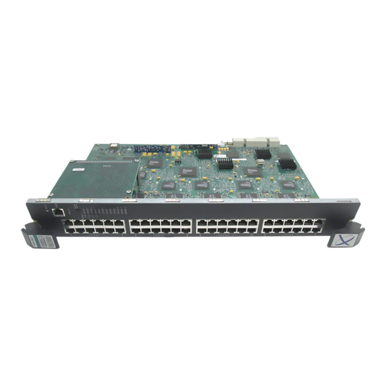
Figure 1-1 The 5H102-48 and 5H103-48 Modules Introduction... -
Page 19: Connectivity
History groups are enabled on all ports by default. The Enterasys Networks RMON Actions is a vendor-specific extension of RMON and provides the ability to set an “Action” on any SNMP MIB variable. The Action can be triggered by any RMON Event and/or Alarm. -
Page 20: Port/Vlan Redirect Function
SNMP-compliant Network Management Software, such as Enterasys Networks’ NetSight and Aprisma Management Technology’s SPECTRUM for Open Systems suite of management products. In-band management using Telnet and Enterasys Networks’ Webview is also provided. Out-of-band Local Management is provided through the RJ45 COM port on the front panel using a VT100 terminal or a VT100 terminal emulator. -
Page 21: Switching Options
1.10 STANDARDS COMPATIBILITY The 5H102-48 and 5H103-48 modules are fully compliant with the IEEE 802.3, 802.3u, 802.3x, 802.1D, and 802.1Q standards. The modules provide IEEE 802.1D Spanning Tree Algorithm (STA) support to enhance the overall reliability of the network and protect against “loop”... -
Page 23: Network Requirements
Failure to do so will produce poor network performance. NOTE: The MATRIX E5 Series Modules Local Management User’s Guide and Cabling Guide referred to in the following sections can be found on the Enterasys Networks World Wide Web site: http://www.enterasys.com/... -
Page 24: 100Base-Tx Network
100BASE-TX Network 100BASE-TX NETWORK The fixed front panel ports of the module provide a connection that supports Category 5 UTP cabling. The device at the other end of the twisted pair segment must meet IEEE 802.3u 100BASE-TX Fast Ethernet network requirements for the devices to operate at 100 Mbps. Refer to the Cabling Guide for details. -
Page 25: Installation
NOTE: Read the Release Notes shipped with the module to check for any exceptions to the supported features and operation documented in this guide. This chapter provides the instructions to install the 5H102-48 or 5H103-48 module. A Phillips screwdriver is required to install options into the module. Follow the order of the sections listed below to correctly install the module. -
Page 26: Contents Of Module Carton
1. Open the box and remove the packing material protecting the module. 2. Verify the contents of the carton as listed in Table 3-1 Contents of Module Carton Item One module, either the 5H102-48 or the 5H103-48 Antistatic Wrist Strap RJ21 Angle Adapter Manual Accessory Kit 3. -
Page 27: Installing The Module Into The 5C105 Chassis
Observe all precautions to prevent damage from Electrostatic Discharge (ESD). 5. Examine the module for damage. If any damage exists, DO NOT install the module. Immediately contact Enterasys Networks. Refer to CAUTION: To prevent damaging the backplane connectors in the following step, take care that the module slides in straight and properly engages the backplane connectors. -
Page 28: Installing A Module Into The 5C105 Chassis
Installing the Module into the 5C105 Chassis Figure 3-1 Installing a Module into the 5C105 Chassis SERIES RESET Installation... -
Page 29: Connecting To The Network
3.3.1 Connecting UTP Cables to the 5H102-48 The fixed front panel ports of the 5H102-48 are 10/100 RJ45 ports with internal crossovers. When connecting a workstation to these ports, use a straight-through cable. When connecting networking devices to these ports, such as a bridge, repeater, or router, use a crossover cable. -
Page 30: Connecting A Twisted Pair Segment To The 5H102-48
Connecting to the Network Figure 3-2 Connecting a Twisted Pair Segment to the 5H102-48 3. Verify that a link exists by checking that the port RX (Receive) LED is ON (flashing amber, blinking green, or solid green). If the RX LED is OFF and the TX (Transmit) LED is not blinking amber, perform the following steps until it is on: a. -
Page 31: Crossover Cable Rj45 Pinouts
Ensure that the twisted pair connection meets the dB loss and cable specifications outlined in the Cabling Guide. Refer to document. If a link is not established, contact Enterasys Networks. Refer to Guide for details. 4. Repeat all the steps above until all connections have been made. -
Page 32: Connecting Utp Cables To The 5H103-48
Connecting to the Network 3.3.2 Connecting UTP Cables to the 5H103-48 When facing the front panel of the 5H103-48, the RJ21 connectors from top to bottom represent Ethernet/Fast Ethernet segments 1 through 12, segments 13 through 24, 25 through 36, and 37 through 48, respectively. -
Page 33: Connection Using The Rj21 Angle Adapter
Connecting to the Network Figure 3-6 Connection Using the RJ21 Angle Adapter Figure 3-7 Example of Cable Placement When Using the RJ21 Angle Adapters Installation... -
Page 34: Completing The Installation
Verify that the RJ21 connectors on the twisted pair segment have the proper pinouts and check the cable for continuity. c. Check that the twisted pair connection meets the specifications in the Cabling Guide. If a link is not established, contact Enterasys Networks. Refer to Guide for details. -
Page 35: Troubleshooting
This chapter provides information concerning the following: • Using LANVIEW (Section • Troubleshooting Checklist • Using the RESET Button USING LANVIEW The modules use a built-in visual diagnostic and status monitoring system called LANVIEW. The LANVIEW LEDs (Figure 4-1) allow quick observation of the network status to aid in diagnosing network problems. -
Page 36: Lanview Leds (Both Modules)
Using LANVIEW Figure 4-1 LANVIEW LEDs (both modules) Table 4-1 describes the LED indications and provides recommended actions as appropriate. NOTE: The terms flashing, blinking, and solid used in Flashing indicates an LED is flashing randomly. Blinking indicates an LED is flashing at a steady rate (approximately 50% on, 50% off). Solid indicates a steady LED light. - Page 37 Solid. Diagnostic failure. Using LANVIEW Recommended Action Ensure chassis has adequate power. If the LED remains red for several minutes, contact Enterasys Networks for technical support. None. If the LED remains amber for more than several minutes, contact Enterasys Networks for technical support.
- Page 38 (100BASE-TX). Troubleshooting Recommended Action 1. Ensure that the STA is enabled and that there is a valid link. 2. Contact Enterasys Networks for technical support. None. 1. Ensure that the port is not disabled. 2. Contact Enterasys Networks for technical support.
-
Page 39: Troubleshooting Checklist
TROUBLESHOOTING CHECKLIST If the module is not working properly, refer to causes, and recommended actions to resolve the problem. Table 4-2 Troubleshooting Checklist Problem Possible Cause All LEDs are Loss of power. OFF. No Local Autobaud is enabled, but Management the baud rate has not yet Password screen. - Page 40 Troubleshooting Checklist Table 4-2 Troubleshooting Checklist (Continued) Problem Possible Cause Cannot contact IP address not assigned. the module through in-band management. Port is disabled. No link to device. Port(s) goes into Loop condition detected. standby for no apparent reason. User parameters 1.
-
Page 41: Using The Reset Button
USING THE RESET BUTTON The RESET button shown in CAUTION: Pressing the RESET button resets the device, and all current switching being performed by the module is halted. A network downtime of up to two minutes will result from this action for any devices connected to the module. Figure 4-2 RESET Button (both modules) To reset the module processor, press and release the RESET button. -
Page 43: Module Specifications
This appendix provides operating specifications for the 5H102-48 and 5H103-48 modules. Enterasys Networks reserves the right to change the specifications at any time without notice. If not specified by module name, the statistics are the same for both modules. MODULE SPECIFICATIONS... -
Page 44: Input/Output Ports
Input/Output Ports INPUT/OUTPUT PORTS 5H102-48: Ports 1 through 48: 5H103-48: Ports 1 through 48: COM PORT PINOUT ASSIGNMENTS The COM port is a serial communications port that supports Local Management. the COM port pin assignments. Table A-1 COM Port Pin Assignments... -
Page 45: Regulatory Compliance
REGULATORY COMPLIANCE The 5H102-48 and 5H103-48 modules meet the following safety and electromagnetic compatibility (EMC) requirements: Safety: Electromagnetic Compatibility (EMC): UL 1950, CSA C22.2 No. 950, 73/23/EEC, EN 60950, IEC 950, EN 60825 FCC Part 15, CSA C108.8, 89/336/EEC, EN 55022,... -
Page 47: Mode Switch Bank Settings And Options
Mode Switch Bank Settings and Options This appendix covers the following items: • Required tools (Section • Locations, functions, and settings for the mode switches REQUIRED TOOLS Use the following tools to perform the procedures provided in this appendix: • Antistatic wrist strap •... -
Page 48: Setting The Mode Switches
These switches are set at the factory and rarely need to be changed. Switch definitions and positions are as follows: • Switches 1 through 4 – For Enterasys Networks use only. • Switch 5 – If the boot up diagnostics have been disabled, changing the position of this switch will enable them. - Page 49 • Switch 6 – No function. • Switch 7 – Clear NVRAM. Changing the position of this switch resets NVRAM on the next power-up of the device. All user-entered parameters, such as the IP address, device names, etc., are reset to the factory default settings. Once the module resets, you can either use the factory default settings or reenter your own parameters.
-
Page 51: Index
Numerics 100BASE-TX requirements 10BASE-T connection 3-5, requirements 802.1p Port Priority introduction to Auto-Negotiation Cable connections 5H102-48 5H103-48 Cable specifications 100BASE-TX network 10BASE-T network COM port pin assignments Connecting to the network Connectivity introduction to Document conventions xiii Environmental requirements Flow Control... - Page 52 Physical properties Pinouts crossover straight-through Port redirect function introduction to Port Trunking introduction to Receive LEDs viewing of Redirect functions port and VLAN introduction to Regulatory Compliance Related manuals Remote Monitoring (RMON) introduction to RESET button Index-2 Specifications Standards compatibility Switching options introduction to Transmit LEDs...