Table of Contents
Advertisement
Quick Links
Save This Manual
For Future Reference
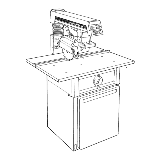
I 0" ELECTRONIC
RADIALSAWWITH
23" CABINET AND
1 DOOR
S_rial
Number
...........
Model
and s_rial numbers
may b_ found
on the
backside
of the base
You should
record both
model
and s_rial number
in
a place
for future us_,
CAUTION:
READALL
INSTRUCTIONS
CAREFULLY
I
® assembly
® operating
• repair parts
Sold by SEARS, R OEBUCKAND CO., Chicago,
IL 60684 U.S.A.
Part No, SP5016
Printed in US.A.
Advertisement
Table of Contents

Related Manuals for Craftsman 113.198210


Summary of Contents for Craftsman 113.198210
- Page 1 Save This Manual For Future Reference I 0" ELECTRONIC RADIALSAWWITH 23" CABINET AND 1 DOOR S_rial Number ... Model and s_rial numbers may b_ found on the backside of the base You should record both model and s_rial number a place for future us_, CAUTION: ®...
- Page 2 FULL ONE YEAR WARRANTY ON CRAFTSMAN RADIAL If within one year from the date of purchase, this Craftsman Radial Saw fails due to a defect tn material or workmanship, Sears will repair It, free of charge,, WARRANTY SERVICE IS AVAILABLE BY SIMPLY CONTACTING...
- Page 3 additionaU instructions for radiaU saws t'¢= L-- OO*-, BEFORE USING THE SAW: WARNING: TO AVOID MISTAKES THAT COULD expected contact with the workpiece, fence, RESULT IN SERIOUS, PERMANENT INJURY, DO table or part of your body NOT CONNECT POWER CORD UNTIL THE FOL- LOWING STEPS HAVE BEEN SATISFACTORILY BEFORE...
- Page 4 while the cutting tool is rotating. The rotating of a second is sufficient to inflict severe, permanent tool could cut and throw anything hitting the injury blade caus{ngthe saw to unexpectedly come if your saw makes an unfamiliar noise or' if it forward vibrates excessively, stop the operation...
- Page 5 fromthe noseside(opposite thesawdust e xhaust To avoid kickbacks never feed a workpiece chute) of the guard. Note the warningon the through with another piece (butting _'_-_ guard.. second piece against trailing end of piece being '_ = cut) even if of the same thickness, To keep control of your workpiece, never rip work shorter than the blade diameter...
- Page 6 provide additional guarding from contact with the Always return the carriage to the full rearward front of the blade. position behind the fence at the completion each crosscut type operation Never remove your' To prevent the cutting tool from grabbing hand from the yoke handle unless the carriage table or workpiece and being propelled...
- Page 7 Outrip Sawblade Path Positioningthe bladeparallel t o the fencewith the The area of the workpiece or table top directly in line motortowardthe rearof the sawproducingmaxi- with either the travel of the blade or the part of the mumrippingcapacity_ S eeillustrationon page37, workpiece which will be, or has been, cut by the...
- Page 8 It is recommended t hatyou havea qualifiedelectri- 4. Frequent "blowing" of fuses or tripping of circuit cian replacethe two prong outlet with a properly breakers may result if: groundedthreeprongoutlet, (a) MOTOR IS OVERLOADED - Overloading Anadapter asshownbelowis available for connect- occur-if feed too rapidly or' if saw is...
- Page 9 contents Page Page Guarantee ........Location and Function of Controls .... General Safety Instructions for Power Tools ..Basic Saw Operations ......Additional Safety Instructions for Radial Saws oo 3 Adjustments to Compensate for Wear ..Glossary of Terms for Woodworking ...
- Page 10 unpacking and pteassembly ITEM DESCRIPTION QTY,. Basic Saw Assembly ....WARNING: TO AVOID INJURY FROM UNEXPECT- Rear Table ......ED STARTING OR ELECTRICAL SHOCK, DO NOT Table Spacer : ...... PLUG THE POWER CORD INTO A SOURCE Rip Fence ......POWER.
- Page 11 unpacking and checking contents 1, Separate all "loose" parts from packing materials WARNING: If any parts are missing, do not attempt and check each item with "Parts List" to make to assemble the radial arm saw, plug in the power sure all items are accounted for before discarding cord, or turn on the switch until the missing parts are any packing material...
- Page 12 23" CABINET ASSEMBLY NO. 507493 FOR MODEL NO. 113.198210 Right Side Panel ......B Left Side Panel ......Lower' Shelf ....... D Skirt ........E Shelf Stiffener ......Corner Bracket ......G Spacer ........Door'........Caster, Stationary ......... i i ii i:llllllllll i lllllll...
- Page 13 SKIRT SIDE PANEL 7. Locate the two (2) skirts, eight (8) 1/4-20 x 1/2 truss head bolts, Iockwashers and hex nuts. Assemble the one (1) skirt to the front of the cabinet through the holes as illustrated. Stand the cabinet upright and assemble the rear skirt "\ FRONT...
- Page 14 CHECKING CABINET FOR SQUARENESS TOOLS NEEDED: Framing square, 3/4" wrench and 7/16" wrench or socket. 1 With cabinet on back side place a square lower shelf next to right side panel, Adjust stand so both right side panel and lower shelf touch square (as illustrated) Then tighten nut holding rear of shelf to side panel and right side spacer to...
- Page 15 iVIOUNTBNG DOOR Tools needed: 7/16" wrench or socket and phillips screwd river, 1, Locate the two (2) door hinges and four (4) 10-14 x 1/2 plastite screw, Mount hinges on either side of the door with phillips screwdriver, 2, Locate the four (4) truss head bolts, lockwasher and hex nuts to attach door hinges to the side panel, Tighten...
- Page 16 ATTACHING TRiM CAPS & TRiM LEDGE 1. Locate the two (2) trim caps, the trim ledge, and from loose parts bag 498 four (4) sheet metal type "B" #10 x i and six (6) type BT screws 1/4 x 1/2o 2_ Place the trim ledge against the bottom of the base using two (2) type"B"...
- Page 17 ATTACH ELEVATION HANDWHEEL ELEVATION 1 From loose parts bag #497, find one (1) screw ,IANDWHEEL 10-32 x 1/2 and one (I) external Iockwasher Install handwheel to front of base as illustrated MOUNTING MOTOR 1, Remove blade guard, Locate the arbor wrenches and remove the blade_ _,,,,...
- Page 18 ALIIGNMENT PROCEDURE IMPORTANT: In order to obtain maximum cutting accuracy and safety, the following six steps must be carefully followed° Become thoroughly familiar with these steps so that you can always maintain your saw in proper alignment° The accuracy of each adjustment is always dependent upon the accuracy of the preceeding adjustment.
- Page 19 3 Release bevellockhandle, a ndrotatethemotor topositionthesawbladeendofshaftdown.Lock bevelhandle, 4 Unlockand hold miter lock handlein unindex positionasshown, Position armagainstleftstop(approximately 5 0° miter),Loosencarriagelock knobandposition carriagedirectlyoverleft handchannel NOTE: F orsafetyreasons, stopshave beenprovided to prevent 3 60 ° rotationof the radialarm 5. Slidethe arborwrench handlebetweenend ARBOR WRENCH motor shaft and mounting...
- Page 20 4. Install one (1) 1/4 Iockwasher andhex nut on each of the four' (4) screws in the support channels, a ndtightenusingphillipsscrewdriver and7/16wrenchor'socket. 5. Laythe reartableboardonedgeacrossthefront tableto serveasastraightedge_ S ightunderthis straightedgeto determinewhether the front tableboardishighor lowatitscenter. A lsocheck to seeif tableis contactingtheplastictrimcaps installedper page 16.
- Page 21 (c) Carefully retighten tJpper two (2) 1/4_20 socket set screws alternating from left side to right side so as not to force arm out of adjustment° (d) Recheck blade travel° Adjust arm position as needed by readjusting upper screws only, FOUR SOCKET HEAD SCREWS (e) Once arm position...
- Page 22 (c) Loosen the four' (4) socket set screws located behind yoke as illustrated with a 1/8" Hex "L" wrench. Rotate motor while holding square firmly against saw blade and table top until the square touches the sawblade as shown. (d) Lock bevel lock handle Recheck alignment make sure blade did not move when bevel lock handle was locked Tighten...
- Page 23 NOTE: tt may be necessary to use pliers to grip the short end of the (b) Using a 1/8" Hex "L" wrench loosen the four Hex "L" wrench to loosen or tighten socket set screws located through access the socket cap screws° Remember holes on bottom side of yoke as illustrated.
- Page 24 STEP SiX Installing Blade Guard and Adjusting Anti-Kickback Pawls and Spreader GUARD---'-'-'-_ 1._Instatl blade guard on motor. 2. Unlock the swivel lock handle and rotate the blade into the IN-RIP position Lock the swivel lock handle ANT1KICKBACK PAWLS 3. Position blade against fence and lock the rip lock handle, Loosen wing screw and lower the anti- kickback...
- Page 25 tocation and function of the electronic indicator system BATTERY STORAGE COMPARTMENT (ON SIDE) FUNCTION INDICATORS ON/OFF BEVEL ANGLE FUNCTION MITER ANGLE FUNCTION RIP POSITION FUNCTION BLADE ELEVATION FUNCTION REFERENCE SET KEY DIGITAL READOUT DISPLAY LOCK REMOVE V_LLOW eo_- Digital Readout Display The liquid crystal display (LCD) on this saw gives Rip position - displays the distance the blade is from the user the ability...
- Page 26 1. Installing the Battery Install the battery into the compartment as shown The bottom rear tab of the battery should be held inside the compartment by the bottom wall of the casing, BATTERY The indicator display should appear within second or two after the battery is correctly...
- Page 27 Loosen the miter angle encoder mounting LINE UP bracket by backing the mounting screws off until the encoder will rotate slightly on the WITH HOLE column tube, e,, Rotate the encoder on the tube by tapping the encoder lightly until the display reads "450" Do not force or hit the encoder to make this adjustment...
- Page 28 f ff the adjustment will not align the display Press the key, Press _tosetthezero readout to the bevel index positions, refer to reference location blade elevation the trouble shooting guide in this manual readout This display should read: [_LE U_ i g, When the encoder alignment has been com-...
- Page 29 Uocation and function of controns WARNING: FOR YOUR OWN SAFETY ALWAYS WARNING: THE SAWBLADE, DADO, OR CUTTING LOCK THE SWITCH "OFF" WHEN SAW IS NOT IN TOOL MUST BE REMOVED FROM THE SAW USE. REMOVE KEY AND KEEP IT IN A SAFE ARBOR BEFORE USING THE ACCESSORY SHAFT, PLACE,,, ALSO IN THE EVENT OF A POWER...
- Page 30 2. Angle of Cut (Miter) Proper Indexing Method - Experienced operators of woodworking equipment such as this Craftsman Radial Saw, acquire the habit of indexing in one direction only, whenever a new setting is made in preparation for a different operation...
- Page 31 5. Blade Angle (Bevel) a_ A single bevel lock handle is used in angular positioning and indexing of the motor, provide the desired saw blade (bevel) angle. bo The bevel lock handle controls the angular position of the motor with respect to horizontal.. The bevel lock handle automatically indexes the motor...
- Page 32 8. Blade Guard and Anti-Kickback/Spreader Assembly - Positioning for Ripping. GUARD CLAMP WARNING: NEVER POSITION THE GUARD OR SCREW ANTI-KICKBACK/SPREADER ASSEMBLY WITH THE SAW RUNNING, NEVER POSITION THE ANTI- KICKBACK/SPREADER ASSEMBLY BY GRASPING PAWLS OR SPREADER. MAINTAIN SPREADER ALIGNMENT, USE THE TAB LOCATED ON THE ANTI-KICKBACK BAR.
- Page 33 basic saw operation WARNING: TO AVOID MISTAKES THAT COULD CAUSE SERIOUS PERMANENT INJURY, OBSERVE ALL THE FOLLOWING INSTRUCTIONS IN ADDI- TION TO THOSE ON PAGES 2-6. Basic saw operations are summarized in six cate- gories, explained and illustrated in the following paragraphs NOTE: Refer to paragraphs...
- Page 34 2. Make sure the arbor nut is snug. 3. Clamp the guard in a horizontal position. 4. Lock the swivel lock handle Make sure it is firmly locked. (See page 30) 5_ Hold work firmly against table and fence. avoid tipping or throwing of workpieces thicker...
- Page 35 rectangular frame The radial arm is set to a desired angle of cut, swivel and bevel settings at 0 ° and locked. The workpiece being cut is positioned held firmly against the fence and the carriage pulled forward along the radial arm just far enough complete the cut Carriage should then be returned to the full rear position...
- Page 36 board against the fence must be straight and will not catch on kerfs in the fence - for workpieces thicker than the fence is high, install a higher fence (at least the thickness of the workpiece). NEVER RIP"FREEHAND" (without aid offence) 5 Properly set the anti-kickback and spreader...
- Page 37 OPERATION NO. 5 - OUT-RIPPING AND IN-RIPPING 1. Ripping is the process of sawing the workpiece along its length by feeding it into the sawblade when using the fence as a guide and as a positioning device to obtain the desired width of cut.
- Page 38 OPERATION NO. 6 - BEVEL RIPPING Bevel ripping is either in-ripping or out-ripping described above, except the saw blade is tilted out of perpendicular to the saw table surface The radial arm is indexed at 0 ° and locked, the bevel is set to the desired bevel angle and the yoke is positioned for in=ripping...
- Page 39 AUXILIARY FENCE FORMOLDING To use the molding head with the arm in the 0 ° AUXILIARY FENCE SPACER TABLE crosscut position an auxiliary fence must be used WARNING: IF THE AUXILIARY FENCE IS NOT USED WHEN THE SAW ARM IS IN THE 0 ° CROSS- REAR TABLE CUT POSITION,...
- Page 40 5,. Adjustment is complete when both locking indexing functions are working properly Replace motor support cover.. ADJUSTING SWIVEL LOCK HANDLE This handle provides a friction lock between upper face of the yoke and the bottom face of the carriage, It should eliminate any play or rotation between these two parts when locked, An adjustment...
- Page 41 ADJUSTING CARRIAGE BEARINGS The carriage should roll freely but with some resist- ance for the entire length of travel To test for bearing looseness, perform the following steps 1 Place yoke in either the in-rip or out-rip position. 2 Push the carriage back against the rear stop 3, Hold the front carriage bearing with your fingers as tight as possible and pull carriage forward the same time, If you can prevent the bearing...
- Page 42 2, With a 3/16 inch hex "L" wrench find the 1/4-20 hex socket cap screwthrough the hole in the rear arm cover To tighten turn the wrench clockwise approximately 1/4 turn 3 Lock the miter lock handle and try again to move the arm Readjust if necessary 4, If it becomes extremely...
- Page 43 troubUe-shooting HA VE YOU FOLLOWED ALL SIX STEPS OF THE ALIGNMENT PROCEDURE? IF YOU HAVE FOLLOWED THEM IN THEIR PROPER SEQUENCE, CANNOT EXPECT A CCURA TE CUTTING RESUL TS. In addition to the proper alignment of your saw, you THIS EDGE OF BOARD FENCE must also become familiar with the following...
- Page 44 FINISH CUT END FINISH CUT END 1. RADIAL SAW DOES NOT MAKE ACCURATE 0° SQUARE SQUARE or 45 ° MITER CROSSCUTS. a. Looseness between column tube and column support, Align as described in Alignment Procedure Section Step One b, Crosscut travel not properly adjusted.
- Page 45 4. SAWKERF(CUT EDGE)OF STOCKROUGH -TOOTH MARKSLEFT ON EDGE OF SAW KERF, ..ROUGH KERF NOTE: This condition is commonly called "HEEL" EDGE a, Crosscutting or Miter Cutting, "Heeling" will tend to slide the workpiece along the guide fence, as the cut is being made, and make a square cut almost impos- sible.
- Page 46 9. CLAMPING FORCE NOT SUFFICIENTAT MITERANGLES OTHER THAN45° ao Miter Lock Handle requires Adjustment. Refer to Adjusting Miter Lock Handle in Adjust- ments to Compensate for Wear Section 10. CLAMPING FORCE SUFFICIENT BEVEL ANGLES OTHER THAN 45 °. a, Bevel Lock Handle Requires adjusting. Refer to Adjusting Bevel Lock Handle in Adjust- ments to Compensate for Wear Section,...
- Page 47 TROUBLE SHOOTING GUIDE - ELECTRONICS PROBLEM PROBABLE CAUSE SUGGESTED CORRECTIVE ACTION No display when 1, Battery incorrectly - Adjust battery position in compartment. installed is pressed. - Clean battery contacts, 2 Battery contacts dirty or corroded 3. Battery dead - Replace battery, Battery is 6 volt, size J, alkaline type - Have electronics checked...
- Page 48 MOTOR TROUBLE-SHOOTING CHART NOTE: Motors used on wood-working tools are particularly susceptible to the accumulation sawdust and wood chips and should be blown out or "vacuumed" frequently to prevent interference with normal motor ventilation. TROUBLE PROBABLE CAUSE SUGGESTED REMEDY Motor will not run. !, Low voltage 1.
- Page 49 Swivel to OR LUBRICATING YOUR SAW. in-rip or out-rip for easy access to the swivel index When you receive your new Craftsman radial saw, it pin., Bevel saw to 45 ° and bevel index pin can be requires no lubrication.
- Page 50 A light film ofoi! shouldbewipedonthe faceof the columntubeto lubricatethefit between thecolumn tubeandcolumnsupport. W ithelevation crankraise armto upperlimit Completely collapsebellowsby pulling downon top flangeas illustratedfor-access to columntube. The threadon theelevationshaftassembly can be lubricatedthroughthe oil holein the centerof the radialarmcap Lubricaterampon the swivelindex spring.
- Page 51 NOTES...
- Page 52 PARTS LIST FOR CRAFTSMAN 10" ELECTRONIC RADIAL MODEL NO. 113.198210 28--_ FIGURE...
- Page 53 PARTS LIST FOR CRAFTSMAN 10" ELECTRONIC RADIAL SAW MODEL NO. 113.198210 Always order by Part Number - Not by Key Number FIGURE Part Part Description Description ill,, STD601103 *Screw, Pan Rec. 815774 Rivet 1/4 x 1/2 60297 Type T 10-32 x 3/8...
- Page 54 PARTS LIST FOR CRAFTSMAN 10" ELECTRONIC RADIAL MODEL NO. 113.198210 FIGURE...
- Page 55 PARTS LIST FOR CRAFTSMAN 10" ELECTRONIC RADIAL MODEL NO. 113.198210 Always order by Part Number - Not by Key Number FIGURE 2 - BASE AND COLUMN ASSEMBLY Part i(ey Key I Part Description No. l Description i,i,,i, i,i,,, _ ,_..
- Page 56 PARTS LIST FOR CRAFTSMAN 10" ELECTRONIC RADIAL MODEL NO. 113.198210 FIGURE...
- Page 57 PARTS LIST FOR CRAFTSMAN 10" ELECTRONIC RADIAL SAW MODEL NO. 113.198210 Always order by Part Number - Not by Key Number FIGURE 3 - YOKE AND MOTOR ASSEMBLY Part KeY I Part Description ..... Description 815799 815803 Cap, Motor Support...
- Page 58 PARTS LIST FOR CRAFTSMAN 10" ELECTRONIC RADIAL MODEL NO. 113.198210 FIGURE...
- Page 59 PARTS LIST FOR CRAFTSMAN 10" ELECTRONIC RADIAL SAW MODEL NO. 113.198210 Always order by Part Number - Not by Key Number FIGURE 4 - YOKE ASSEMBLY Part Part Description Description Hi,i, iSTD541231 810214-3 *Nut, Hex Jam 5/16-18 Screw, Low Hd..
- Page 60 PARTS LIST FOR CRAFTSMAN 10" ELECTRONIC RADIAL MODEL NO. 113.198210 FIGURE...
- Page 61 PARTS LIST FOR CRAFTSMAN 10" ELECTRONIC RADIAL MODEL NO. 113.198210 Always order by Part Number - Not by Key Number FIGURE 5 - ARM ASSEMBLY Part Part Description Description 815688 Arm, Radial STD601103 *Screw, Pan Rec, Hd, 815809 Cable Type "T" #10-32 x 3/8...
- Page 62 PARTS LIST FOR CRAFTSMAN 10" ELECTRONIC RADIAL MODEL NO. 113.198210 Always order by Part Number - Not by Key Number FIGURE 6 - GUARD ASSEMBLY Part Part Description Description iNo. ,,,,,,,,,,,,,,,,,,,,,, ,,,, ,, ,,,, ,, ,,,,,,, ;11 IUI 816264 Guard...
- Page 63 PARTS LIST FOR CRAFTSMAN 10" ELECTRONIC RADIAL MODEL NO. 113.1982'10 Always order by Part Number - Not by Key Number FIGURE 7 - TABLE ASSEMBLY Part Description ..8t5794 Table, Rear 815795 Table Spacer 63432 Fence, Rip 815796 Table, Front...
- Page 64 PARTS LiST FOR CRAFTSMAN 10" ELECTRONIC RADIAL MODEL NO. 113.198210 PARTS LIST 23" CABINET Always order by Part Number - Not by Key Number Part Part No° Description Description ..... i,ll ,, 815934 805589_5 Hinge, Door Screw, Truss Hd,, 815993...
- Page 65 NOTES...
- Page 66 NOI'_S...
- Page 67 NOTES...
- Page 68 ¸ ,,,ll SERVICE Now that you have purohas_d your 10-inch eleclTonic radial saw, should a need ever exist for repair pars or sen4ce, simply contact any S_ars Sen/ice C_nter and most Sears, Roebuck Co. stores. Be sure to provide al! pertinent facts when you cail or visit.