Table of Contents
Advertisement
S
Save This Manual'_
For Future Reference
owner's
manual
MODEL NO.
113.196221
113.196321
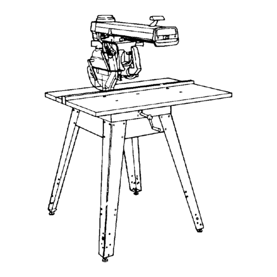
SAW WITH LEGS
or
113.196421
CONTRACTOR'S SAW
Serial
Number.
Model
and serial numbers
may be found
at the front
of the base.
You should record
both
model and serial number
in
a safe place
for future use.
FOR YOUR
SAFETY:
READ ALL
INSTRUCTIONS
CAREFULLY
_'_E_A/F_S
/ I:RI1FT$ M RN
10-1NCH RADIAL SAW
• assembly
• operating
• repair parts
\
Sears Roebuck
and Co., Hoffman
Estates, IL 60179 U.S.A.
Part No. SP5667
Printed
in U.S.A.
Advertisement
Table of Contents

Related Manuals for Craftsman 113.196421


Summary of Contents for Craftsman 113.196421
- Page 1 Save This Manual'_ For Future Reference owner's manual MODEL NO. 113.196221 113.196321 SAW WITH LEGS 113.196421 CONTRACTOR'S SAW Serial _'_E_A/F_S / I:RI1FT$ M RN Number. Model and serial numbers may be found at the front of the base. 10-1NCH RADIAL SAW You should record both model and serial number...
- Page 2 Aides ......................Accessories ......................Maintenance ......................Troubleshooting ..................... Repair Parts ......................FULL ONE YEAR WARRANTY ON CRAFTSMAN STATIONARY TOOL If, this stationary tool fails due to a defect in material or workmanship within year from the date of purchase, CONTACT...
- Page 3 Safety M_or Hazards This manual has safety information instructions to help users eliminate or reduce Three major hazards are associated with the risk of accidents and injuries, including: using the radial arm saw for ripping. They i. Severe cuts, and loss of fingers or other are outfeed zone hazard, kickback, body parts due to contact with the blade.
- Page 4 Safety Kickback Hazard Kickback is the uncontrolled propelling WARNING the workpiece back toward the user during ripping. The cause of kickback is the binding or pinching of the blade in the workpiece. Several conditions can cause the blade to bind or pinch. KICKBACKIII_ When a workpiece kicks back, it could hit hard enough to cause internal organ injury,...
- Page 5 Safety Guard Function and Features The guard is a very important safety feature, designed to reduce the risk of injury associ- ated with blade contact. Install the guard correctly. Follow the specific instructions in the ripping and crosscutting sections set and use the guard correctly for each ty pe of cut.
- Page 6 Safety the pawls/riving knife knob. When lowered for crosscutting, it acts as a barrier to the leading edge of the blade. 6. Set of pawls to be lowered to the work- piece surface for ripping. They allow the workpiece to pass freely from infeed to out- feed side, but help stop the kickback motion Guard from ouffeed to infeed side by grabbing into...
- Page 7 Safety Safety Instructions Read and follow all safety instructions. Personal Safety Instructions 1. Wear safety goggles labeled "ANSI Z87.1" on the package. It means the goggles meet impact standards set by the American National Standards Institute. Regular eye- glasses are not safety goggles. Safety Goggles 2.
- Page 8 Safety Saw Safety Instructions 6. Before turning on saw, clear table of all 1. Use guard, pawls and riving knife accord- ing to instructions. Keep them in working objects except workpiece to be cut and nec- order. essary fixtures, clamps, or feather-boards. 2.
- Page 9 Safety 3. Rip only workpieces longer than the diameter of the blade. Do not rip workpieces that are shorter than the diameter of the blade being used. 4. Workpieces that extend beyond the saw table can shift, twist, rise up from the table, or fall as they are cut or afterwards.
- Page 10 Safety On-Product Safety Labels Note where they are located on the saw. Read and follow the safety information There are several safety labels on the saw. and instructions in these labels. Refer to They alert the user to hazards explained the manual for detailed explanations the manual and remind the user how to instructions.
- Page 11 Safety Near the saw handle is dais safety label to ,&WARNING "alert you to thrown objects and to remind you to wear safety goggles: On the clear plastic guard is this label: TO AVOID INJURY SHUT OFF POWER BEFORE CLEANING WARNING: JAMMED LOWER...
- Page 12 Assembly Introduction In order to get the most enjoyment out of your radial saw it is important that the machine by properly assembled, adjusted, and aligned. This procedure, although not difficult, takes time; perhaps eight hours or longer for the inexperienced user.
-
Page 13: Table Of Contents
Assembly All models include: 5/16" diam. hex nut (4) 5/16" - 18 x 3/4" long 1/4" diam. hex nut (4) square head screw (4) _llqqillllll[tllllliO 1/4"-20x 1"long pan head screw (4) 1/4" hex "_ _ IillJllilll_liH_l_l_lilllllil,lt_ 1/4" - 20 x 1-3/4" long 3/16"... -
Page 14: Diam. Hex
Assembly crank arm cap © 1/4" external tooth 1/4" diam. x 5/8" long truss head screw (24) lockwasher (24) (40 for 113.196421) (40 for 113.196421) leveling foot (4) 5/16" diam. external lockwasher 3/8" diatn, hex nut (8) 11/32" x 11/16" x 1/16" washer (8) 5/16"... - Page 15 Assembly _k WARNING 5. Install one 3/8-16 hex nut completely onto each of the leveling feet. Insert one leveling Plugging in saw during assembly foot through hole in bottom of each leg and could result in electrical shock, install a 3/8-16 hex nut. severe cuts from contact with spin- 6.
- Page 16 X in top of legs. 3. Install screws, washers and nuts as shown. If you mount the saw on any other Craftsman base or Slat bench, make sure Elevation Crm_k has proper clearance to Front rotate.
- Page 17 Assembly Attaching Carriage - Motor to Arm Remove carriage stop screw, lockwasher tag. Read and understand warning tag before discarding. Warning (_j_ Lockwasher _,..,._-_ Stop Screw "'-'- Hex "L" Wrench (Supplied) Lock miter/arm lock before proceeding. Push toward rear of Holding carriage assembly with both hands, saw to lock Miter/Arm...
-
Page 18: Square Head
Assembly Remove saw blade. 1. Tighten carriage lock knob, located on right side of ann. 2. Loosen guard clamp screw approximately Purl down 4 turns. to |oo_er} 3. Use one hand to lift the clear plastic guard Blade Rotation at the front of the saw. 4. - Page 19 Adjustments Miter/Arm Lock Lever Arm Lock Adjusting Wheel With the arm at an "unindexed" position and the miter lock applied, the locking action should feel tight and secure. Considerable effort should be required move the ann back towards 0 °. Its is "always possible to force the arm because of the...
- Page 20 Adjustments Yoke Clamp Adjustment Yoke Lock Handle To check the yoke clamp adjustment follow these steps: 1. Pull the yoke lock handle towards the front of saw to unlock yoke. Pull forward on the yoke index lever (on the left side of car- riage) to disengage index pin.
- Page 21 Adjustments Bevel Lock Lever © The purpose of the bevel lock lever is to lock the motor at any angle. To check follow these steps: Bevel 1. Unlock the bevel lock lever. Move the, Index bevel index pin to the left and rotate the saw to approximately 30 °...
- Page 22 Adjustments Arm to Column Adjustment If you can move the end of the radial arm up and down when the ann is unlocked, adjust 3/8-16 Bolts as directed below: a. Remove two (2) screws from rear cover plate. Tighten evenly top two 3/8-16 bolts until arm moves firmly.
- Page 23 Adjustments 2. lax)sen (2) 1/4 - 20 Gib socket cap screws Front on the left side at the rear of the column sup- port slightly (1/2 turn). Hex "L" Wrench "_ (Supplied) 3. Elevate, and then lower the Ann: a. If the column tube binds and elevation Front is difficult, loosen two 5/16 - 18 plated bolts on front side of the column support...
- Page 24 Adjustments Adjusting Carriage Bearings ff the carriage bearings are loose it not only allows the saw blade to move up, down, and sideways but also results in inaccurate cuts. Before following these steps make sure the tracks (steel rods) and carriage bearings have been cleaned by wiping them with a clean cloth.
- Page 25 Adjustments Positioning Table Supports!Installing Front Table/Leveling Front Table Note: The goal in aztjusting the table supports and leveling the front table is to make sure that the table is the same distance from the radial arm at all points. This ensures that when the table and blade are installed the clearance between them will be equal at all points.
-
Page 26: Pan Head
Adjustments Installing Front Table 1. Set out: - front table - tee nut - 1/4" U-clip - 1/4" diam. x 7/8" long cup point set screw - four 1/4" diam x 1" long pan head screws - 1/4" diam. x 1-3/4" long pan head screw - five 17/64"... - Page 27 Adjustments 5. Drop a flat washer into each counter- 1/4-20 x 1" Pan Head Screw bored hole. 1 ;4-20 x |-3/4" 17164" Pan Head Screw Flat Washer 6. Start 1-3/4" long pan head screw through _Front Table center hole and into U-clip, but do not fully tighten.
- Page 28 Alignment ,_WARNING This section applies to all three models cov- ered by this manual. Plugging in saw during alignment could result in accidental start-up The saw and blade must be aligned correctly and severe cuts from contact with for two reasons: spinning blade.
- Page 29 Alignment Miter, Arm Lock Lever 3. Lower arm until saw blade just clears the front table. Lock the yoke lock handle and bevel lock lever. 4. Place a framing square on the table, as shown, with one leg of square t-manly against rear edge of front table.
-
Page 30: Table Clamp
Ali nment Install Table Clamps Front Spacer Rear Table Fence Table Table 1. Insert fence, then spacer table, then rear table. 2. Set out two unassembled table clamps: - two cup washers - two clamp brackets - two square nuts - two thumbscrews 3. -
Page 31: Flat
Alignment Square Blade to Table for Bevel Indicator Crosscutting The goal of this adjustment is to make the blade square to the table so that crosscuts will be accurate; otherwise all crosscuts will have a slight bevel angle. 1. Lower blade until it just dears front table. Lock bevel, miter, rip, and yoke locks. -
Page 32: Fiat
Alignment Square Blade to Fence Left Hand Carriage Cover The goal in setting the blade square to the fence is to reduce the risk of kickback when ripping. This adjustment will also reduce splintering of the workpiece and buming of the keff during ripping and crosscutting. - Page 33 Ali, nment Make Blade Parallel to Table The goal of this adjustment is to keep the workpiece from being thrown or damaged. This adjustment will also reduce splintering of the workpiece and burning of the kerr during ripping and crosscutting. 1.
-
Page 34: Rip Scale
Alignment Installing and Adjusting Rip Scale Indicators. Screw #6-32 x 1/2 Note: The rip scales and pointers are intended to be used for quick settings. For greater accuracy, take direct measurement between blade and fence. _[_Jl'_, Rip Scale 1. Pre-assemble indicator and twin nut. - Page 35 Alignment 6. The blade "Oul-Rip'" scale indicator left hand side of the radial arm is adjusled essentially the same manner as blade "In- Rip" indicator, except position blade with 2 inches between fence and face of saw blade. The rip-scale indicator should be positioned...
- Page 36 Alignment Align Riving Knife to Blade The goal of this adjustment is to position the riving knife directly in line with the blade. Riving knife alignment is an important safe- ty factor. The riving knife rides in the kerf of the cut workpiece during ripping to keep the Fence_...
-
Page 37: Yellow
Controls Bevel Index Lever r Lock Lever Yellow Key Function Control Operation/Comments Pull lever forward to release _ter/Arm Lock Frees radial ann to move; locks index then swing ann left or in any desired position; pre-set right indexed positions at 0 °, 45°L, 45°R Hold in unlocked position while... - Page 38 Controls Yoke Index Lever Table Clamp Bevel Lock Lever Elevation Crank Con_ol Function Operation/Comments BevelLock Lever Frees motor to rotate; locks in Pull lever to release and push to lock any desired position Support motor before unlocking because it can swing down quickly Bevel...
- Page 39 Controls Rip Scale & Indicator Rip Lock Yoke Lock Handle Handle Bevel Lock Lever (ontrol Function Operatio=_iComments Yoke [rock Handle Locks yoke in rip or crosscut Pull handle forward to release; position push handle reward to tighten Yoke index lever must be un- indexed b@)re rotating...
- Page 40 Controls Guard Clamp Screw Guard Pawls/Riving Knife Knob Bracket Riving Knife Pawls Hold Down Control Function Operation/Comments Secures guard to motor; frees Turn counterclockwise Guard Clamp Screw guard for removal loosen, clockwise to tighten Guard Protects against contact with Upper part remains fixed upper blade;...
- Page 41 Controls Pawls/Riving Knife Knob Pawls Riving Knife Function Control Operation!Comments Guard Provides manual way to raise Push and hold until workpiece clear plastic guard during rip- clears guard, then release ping when workpiece fails to raise it Turn _unterclockwise Frees pawls and riving knife to Pawls/Riving Knife Knob...
- Page 42 Electrical Connections WARNING Motor Specifications If not properly grounded, this power The AC motor used on this saw is a capaci- tool could cause electrical shock, tor-start, non-reversible type. The models particularly when used in damp covered in this manual have the following locations.
- Page 43 Electrical Connections WARNING To maintain proper tool grounding, Grounding if outlet you are planning to use for this power tool is a 2-prong type do 3-Prong Make Sure This Is remove alter grounding Plug Connected To A prong in any manner. An adapter is available for connecting...
- Page 44 Electrical Connections Dual Voltage Motors Models 113.196321 and 113.196421 ONLY! To Change Motor Voltage to 240 A.C. Under normal home workshop conditions, full voltage is supplied to the motor, your saw will operate efficiently on 120V. If any of the following conditions exist, it will be advisable to have a qualified electrician reconnect...
- Page 45 Crosscutting Straight Bevel Crosscutting Defined Miter Compound Crosscutting is cutting a workpiece length. The workpiece is held fh-mly against the fence, and the blade is pulled through the work_iece to make the cut. Straight, bevel, miter, and compound cuts can be made. Rolling Carriage Crosscutting Safety...
- Page 46 Crosscutting Crosscut Kerfs A kerf or shallow cut is needed in the table and fence to serve as a path for the blade and to ensure that the blade cuts all the way through the workpiece. A kerf is needed each different cutting path.
- Page 47 Crosscutting Making Crosscuts Follow these steps to make crosscuts. 1 Prepare table: - put fence in front position - tighten table clamps 2. Prepare blade: - lock blade in crosscut posilion - lock radial arm at desired miter angle - lock motor at desired bevel angle*...
- Page 48 Crosscutting Repetitive Crosscutting Carriage Repetitive crosscutting is the repeated and Stop continuous cutting of many pieces of lumber to the same length. Carriage and length stops can help make this type of crosscutting more efficient. A carriage stop def'mes the distance needed to pull the blade through to complete each cut.
- Page 49 Ripping Ripping Defined Ripping is changing the width of a work- piece by cutting along its length. The work- piece is fed into the blade, which rotates in a fixed position, parallel to the fence and a set distance from the fence. A solid fence (no kerfs) serves as a guide for the workpiece.
- Page 50 Ripping Workpiece Positioning Always set up so that the wider part of the workpiece is between the blade and fence. This gives you greater clearance for push sticks, and allows better stability for feeding the workpiece. Example: To rip 2" off a 10" wide board, set blade in in-rip position 8"...
- Page 51 Ripping Outfeed Zone Hazard -_DANGER a DANGER Rotational force of blade can pull hands and fingers back into blade. Touching, holding, or pulling outfeed side of workpiece while blade is still spinning will result in fingers, hand or arm being cut off. To reduce risk of outfeed hazard: Set pawls and riving knife;...
- Page 52 Ripping To reduce risk of kickback: _/Push workpiece through from infeed to ouffeed side until it is completely past _/Set pawls and riving knife according pawls. ripping set-up procedure. Correctly set ",/Use featherboard (see Cutting Aides). riving knife is more likely to prevent workpiece from binding or pinching _/Keep hands away from outfeed side.
- Page 53 Ripping Hold Down Function The hold down must be set correctly during tipping to act as barrier against the infeed side of the blade, to help keep the workpiece flat on the table, and to deflect workpiece chips. It must be lowered to just clear the Set Hold-Down to workpiece.
- Page 54 Ripping WARNING Ripping Set-up Procedure If workpiece is pushed along fence Follow these stepsbefore ripping. with kerfs, workpiece could These steps must be repeated each time a caught on kerf, pinch blade different thickness workpiece is ripped. A cause kickback. Do not use cross- kerf must be made for each different cutting fence for ripping.
- Page 55 Ripping 8. Remove workpiece from table. 9. Ready push stick or push block. 10. Set up table extension(s) and support their outer ends. Do not use another person to support workpieces because this can cause kickback and it exposes helper to potential hazards at outfeed...
- Page 56 Ripping 2. Insert yellow key and turn saw on. 3. Stand at infeed side and out of line of workpiece, in case of kickback. Start and finish cut from infeed side. 4. Put workpiece on table, in front of hold down, and tight against fence.
- Page 57 Ripping Dado Blades, Molding Heads See Accessories for information on safety, installation and use of dado blades and molding heads. Edging Edging is the use of a dado blade or molding head in the horizontal position. It is an advanced technique that requires a molding head guard and a sr,ecial fence.
- Page 58 Cutting Aides Push Stick SLIGHTLY LESS THAN Before cutting any wood on your saw, study THICKNESS OF WORKPIECE 3/4" all of the Crosscutting and Ripping UP TO 3/8" Instructions found on pages 41 through As you learn new radial arm saw wood- €...
- Page 59 Cutti Aides Cutting out the handle Making the handle: • Miter crosscut a piece of 3/4" fllick ply- wood to the shape and size shown. mitered comers can be any size that looks like the drawing (about 1-1/2" by 1-1/2"). 1-112"V Jl 5"...
- Page 60 Cutting Aides Clamp the featherboard to the front table, so that the angled edge of the featherboard against the workpiece on the infeed side of the blade. Do not clamp the featherboard against the cut off part (out-feed side) of the workpiece.
- Page 61 Accessories Accessories Safety Information for Dado 1. Use only accessories listed in this section. 1. Put inside loose collar on arbor shaft first, Use of any other accessory or attachment then install dado. Tighten blade nut directly against outside surface of dado. might increase the risk of injury to you or others.
- Page 62 Accessories Accessories for this Saw These accessories are designed to fit this saw. Read follow instructions that come with accessory. Item ............. Catalog Auxiliary Table Cover ........see catalog Blades (t0" with 5/8" hole) ......see catalog Dado Blades Adjustable Dado 7"-24 toolh carbide ........
- Page 63 Maintenance General Information When new, the saw requires no hthrication. Oil Here Tile saw has been partially aligned and all bearings are lubricated and sealed for life. In time, in order to keep file saw in good work- ing order, it will be necessary to clean, lubri- cate and re-align.
- Page 64 Maintenance Replacing Pawls Make sure the teeth of the pawls are "always sharp. If they become dull the pawls must be replaced: 1. Use 7/16" wrench to remove hex nut. Remove old pawls. 2. Install new pawls, Place spacers exactly as shown.
- Page 65 Troubleshooting HAVE YOU FOLLOWED ALL STEPS OF THE ALIGNMENT PROCEDURE? IF YOU HAVE NOT FOLLOWED THEM IN THEIR PROPER SEQUENCE, YOU CANNOT EXPECT ACCU- RATE CUTTING RESULTS. This Edge ol Board Fence Against Fence For All Cuts In addition to the proper alignment of your saw, you must also become familiar with the following practices in order to expect the...
- Page 66 Troubleshooting What to Do Possible Cause(s) Motor Problem Reduce line load by removing Motor overheats or stalls Overloaded power line other lights, appliances Slow down rate of feed Feeding rote too fast Vacuum sawdust from motor to Improper motor cooling allow normal air circulation Check alignment Saw blade "hasheel...
- Page 67 Troubleshooting Cutting Problem Possible Cause(s) What to Do Inaccurate cut L_x)se locks Check miter, rip, bevel, and swivel locks. See AdiusUnents secliou Saw blade out of alignment Ch c_:k alignment Cros.scuts not accurate at indexed Sawdust between workpiece Keep front table clean fence miter positions Fence not straight...
- Page 68 Troubleshooting What to Do Possible Cause(s) Cutting Problem Align riving knife to blade Riving knife nol in line with blade Workpiece strikes riving knife dur- ing ripping Saw blade out of "alignment Re-align Workpiece binds, smokes, and motor slows or stops when ripping Do not cut ,severely warped pieces Warped workpiece Slow feed rote...
- Page 69 Notes...
- Page 70 "--4 PARTS LIST FOR CRAFTSMAN 10" RADIAL SAW MODEL NUMBERS 113.196221; 113.196321 & 113.196421 "13 e,,,,,i- 25 26 27 RGURE1...
- Page 71 PARTS LIST FOR CRAFTSMAN 10" RADIAL SAW MODEL NUMBERS 113.196221; 113.196321 & 113.196421 Always order by Part Number - Not by Key Number FIGURE 1 Part Part Description Descriplion 63518 Cord, with Plug 821368 Table, Spacer 75090 Cover, Rear Arm...
- Page 72 PARTS LIST FOR CRAFTSMAN 10" RADIAL SAW MODEL NUMBERS 113.196221; 113.196321 & 113.196421 28 2 • Any attempt to repair this motor may create a HAZARD unless repair is done by a qualified service technician. Repair service is available at your nearest Emerson Retail Store.
- Page 73 PARTS LIST FOR CRAFTSMAN 10" RADIAL MODEL NUMBERS 113.196221; 113.196321 & 113.196421 FIGURE 2 - YOKE ASSEMBLY Part Part Description Description STD601105 63469 * Screw, Type "F' Pan Rec. Hd Bushing, Rubber 10-32 x 1/2 63642 Yoke 63661 Cover, L.H. Carriage...
- Page 74 PARTS LIST FOR CRAFTSMAN 10" RADIAL SAW MODEL NUMBERS 113.196221; 113.196321 & 113.196421 28 46 45 FIGURE 3...
- Page 75 PARTS LIST FOR CRAFTSMAN 10" RADIAL MODEL NUMBERS 113.196221 ; 113.196321 & 113.196421 Always order by Part Number - Not by Key Number FIGURE - 3 BASE ASSEMBLY Part Part Description Description STD503705 * Screw, Soc. Set 3/8-16 x 1/2 60300 Washer, 1/2 x 7/8 x .010...
- Page 76 PARTS LIST FOR CRAFTSMAN 10" RADIAL SAW MODEL NUMBERS 113.196221; 113.196321 & 113.196421 "0 Always order by Part Number - Not by Key Number imlml ii "0 Location of Lower Guard Lower GuardS,ot .,___r Washer Screw SEE DETAIL "A" Lower...
- Page 77 PARTS LIST FOR CRAFTSMAN 10" RADIAL SAW MODEL NUMBERS 113.196221; 113.196321 & 113.196421 Always order by Part Number - Not by Key Number FIGURE 4 - GUARD Part Part Description Description 821217 820519 Screw, Guard Clamp Nut, Slotted 1/4 - 20...
- Page 78 Repair Parts PARTS LIST FOR CRAFTSMAN 10" RADIAL SAW MODEL NUMBERS 113.196221, 113.196321 & 113.196421 FIGURE 5 - ARM ASSEMBLY Part Part Description Description 63626 63637 Housing, Pin 63629 Pin, Arm Index 63636 Pin, Clevis 63631 63773 InsuLation Pawl, Arm Lock...
- Page 79 Repair Parts PARTS LIST FOR CRAFTSMAN 10" RADIAL MODEL NUMBERS 113.196221, 113.196321 & 113.196421 FIGURE LEG SET Part Part Description Description 821343 STD551031 * Washer, 11/32 x 11/16 x 1/16 60314 Screw, Truss Hd. 1/4-20 X 5/8 STD551131 * Lockwasher, External 5/18...
- Page 80 10-1NCH RADIAL SAW owner's manual SERVICE For the repair or replacement parts you need Call 7 am - 7 pm, 7 days a week MODEL NO. 1-8OO-366-PART 113.196221 (1-800-366-7278) 113.196321 SAW WITH LEGS 113.196421 For in-home major brand repair service CONTRACTOR'S Call 24 hours a day, 7 days a week 1-800-4-REPAIR...