Carrier 30XA080-500 Controls, Start-Up, Operation, Service And Troubleshooting Instructions
Air-cooled liquid chillers
Hide thumbs
Also See for 30XA080-500:
- Installation instructions manual (8 pages) ,
- Installation instructions manual (8 pages)
Table of Contents
Advertisement
Quick Links
30XA080-500
Air-Cooled Liquid Chillers
60 Hz
Controls, Start-Up, Operation, Service
and Troubleshooting
CONTENTS
Page
SAFETY
CONSIDERATIONS
......................
2
GENERAL
......................................
2-4
Conventions
Used in This
Manual
................
2
Display
Module
Usage
...........................
3
•
NAVIGATOR
TM
DISPLAY
MODULE
CONTROLS
...................................
4-41
General
..........................................
4
Main Base Board (MBB)
..........................
4
Compressor
Protection
Module
(CPM)
...........
6
Electronic
Expansion
Valve (EXV)
Board
.........
9
Fan Boards ......................................
11
Enable-Off-Remote
Contact
Switch
(SWl)
.......
13
Emergency
On/Off
Switch
(SW2) ................
13
Energy
Management
Module
(EMM) .............
13
Local Equipment
Network
.......................
14
Board Addresses
................................
14
Control
Module
Communication
.................
14
•
RED LED
•
GREEN LED
•
YELLOW
LED
Carrier
Comfort
Network®
(CCN)
Interface
......
15
Configuration
Options
..........................
15
•
RAMP LOADING
•
MINUTES
OFF TIME
Dual Chiller
Control
.............................
15
•
DUAL CHILLER
PUMP CONTROL
FOR PARALLEL
APPLICATIONS
•
DUAL CHILLER
PUMP CONTROL
FOR SERIES
CHILLER
APPLICATIONS
Capacity
Control
................................
16
•
EQUAL
LOADING
•
STAGE LOADING
•
CAPACITY
CONTROL
OVERRIDES
Head
Pressure
Control
..........................
22
•
LOW AMBIENT
TEMPERATURE
HEAD PRESSURE
CONTROL
OFf'ION
•
LOW AMBIENT
TEMPERATURE
HEAD PRESSURE
CONTROL
OPERATING
INSTRUCTIONS
Machine
Control
Methods
.......................
29
•
SWITCH
CONTROL
•
TIME SCHEDULE
•
CCN CONTROL
•
UNITRUN
STATUS
Cooling
Set Point Selection
.....................
3O
•
SET POINT
1
•
SET POINT
2
•
4 TO 20 mA INPUT
•
DUAL SWITCH
•
ICE MODE
•
SET POINT
OCCUPANCY
Temperature
Reset
..............................
31
Demand
Limit ...................................
32
•
I-STEP
SWITCH
CONTROLLED
•
2-STEP
SWITCH
CONTROLLED
Page
• EXTERNALLY POWERED (4 to 20 mA Controlled)
• CCN LOADSHED CONTROLLED
Remote
Alarm and Alert Relays
.................
4O
PRE-START-UP
..................................
41
System
Check ...................................
41
START-UP ....................................
42-48
Actual Start-Up ..................................
42
Operating
Limitations
...........................
42
• TEMPERATURES
• VOLTAGE
• MINIMUM FLUID LOOP VOLUME
• FLOW RATE REQUIREMENTS
OPERATION ..................................
48-55
Sequence
of Operation
..........................
48
• ACTUATED BALL VALVE (ABV)
Dual Chiller Sequence
of Operation
.............
49
• PARALLEL PUMP OPERATION
Operating Modes ................................
49
Sensors .........................................
52
• THERMISTORS
• TRANSDUCERS
SERVICE .....................................
56-66
Economizer
Assembly
..........................
56
Electronic
Expansion
Valve (EXV) ...............
56
• MAIN EXV CONTROL
• ECONOMIZER EXV CONTROL
• EXV TROUBLESHOOTING
PROCEDURE
Compressor
Assembly
..........................
59
• COMPRESSOR
OIL SYSTEM
Cooler ...........................................
61
• SUCTION SERVICE VALVE
• FREEZE PROTECTION
• LOW FLUID TEMPERATURE
• LOSS OF FLUID FLOW PROTECTION
• TUBE PLUGGING
• RETUBING
• TIGHTENING COOLER HEAD BOLTS
• INSPECTING/CLEANING
HEAT EXHANGERS
• WATER TREATMENT
• CHILLED WATER FLOW SWITCH
Condenser
Coil Maintenance and Cleaning
Recommendations
............................
64
• REMOVE SURFACE LOADED FIBERS
• PERIODIC CLEAN WATER RINSE
• ROUTINE CLEANING OF COIL SURFACES
Condenser
Fans
................................
65
Refrigerant
Circuit
..............................
65
• LEAK TESTING
• REFRIGERANT CHARGE
Safety
Devices
..................................
66
• COMPRESSOR
PROTECTION
• OIL SEPARATOR HEATERS
• COOLER PROTECTION
Relief Devices ...................................
66
• PRESSURE RELIEF VALVES
Manufacturer
reserves the right to discontinue, or change at any time, specifications
or designs
without notice and without incurring obligations.
Catalog No. 533-00069
Printed in U,S.A,
Form 30XA-1T
Pg 1
12-05
Replaces:
New
Advertisement
Table of Contents

Related Manuals for Carrier 30XA080-500


Summary of Contents for Carrier 30XA080-500
- Page 1 Module Communication ....Operating Modes ........ Sensors ......... • RED LED • THERMISTORS • GREEN LED • TRANSDUCERS • YELLOW SERVICE ........56-66 Carrier Comfort Network® (CCN) Interface ..Configuration Options ......Economizer Assembly ......• RAMP LOADING Electronic Expansion Valve (EXV) ....
-
Page 2: Safety Considerations
CONTENTS (cont) MAINTENANCE ........Recommended Maintenance Schedule ..This unit uses a microprocessor-based electronic control TROUBLESHOOTING ......66-86 system. Do not use jumpel.s or other tools to short out com- ponents, or to bypass or otherwise deDut from recom- Alarms and Alerts ....... -
Page 3: Off
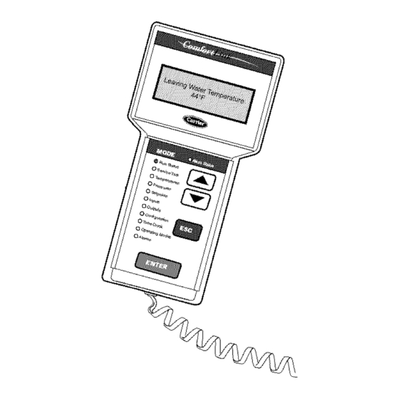
Display Module Usage Pressing will cause the "OFF" to flash. Use the down arrow to change "OFF" to "ON." Pressing NAVIGATOR DISPLAY MODULE -- The Navigator mod- will illuminate all LEDs and display all pixels in the view ule provides a mobile user interface to the Con_fortLink... -
Page 4: Run Status
LEN (Ix)cal Equipment Network). On/Off switch, an Enable-Off- Remote Contact switch. CCN (Carrier Comfort Network®) bus is also supported. Con- nections to both LEN and CCN buses are made at TB3. For a Main Base Board (MBB) -- Tile MBB is tile heart of... - Page 5 Notation MBB-J1, MBB-J1A, MBB-J1B Power (24 vac supply) 24 vac Ground MBB-J9A, MBB-J9B, MBB-J9C Local Equipment Network MBB-J12 Carrier Communication Network MBB-J5B-CH 17 Chilled Water Flow Switch CWFS Switch INPUTS_GEN.I_LOCK Demand Limit Switch No. 1 Demand Limit SWl Switch INPUTS_GEN.I_DLS1...
- Page 6 Compressor Protection Module (CPM) -- There Born'd) and sends the MBB the results of the channels it moni- is one CPM per compressol: See Fig. 3. Tile device controls the tors via the LEN (Local Equipment Network). The CPM has three DIP switch input banks, Switch 1 (SI), Switch 2 ($2), and compressor contactol_,...
- Page 7 Table 3 -- DIP Switch 1 (Sl) Inputs DIP SWITCH POSITION FUNCTION SETTING MEANING Across-the-line Start Starter Configuration Y-Delta Start CT is located in the main line OFF, OFF Current Transformer (CT) Position CT is located in the Delta of the motor OFF, ON Reserved for future use ON, OFF...
- Page 8 Table 4 -- Compressor Protection Module Inputs and Outputs* CONNECTION POINT NAVIGATOR MODULE DESCRIPTION INPUT/OUTPUT I/O TYPE POINT NAME Notation CPM-X-J1 Power (24 vac supply) 24 vac Ground CPM-X-JP12 Local Equipment Network CPM-×-J12 CPM-×-J7-CH05 HPS-X Circuit X High Pressure Switch Switch Not available CPM-X-J6-CH06...
- Page 9 Electronic Expansion Valve (EXV) Board EXV BOARD B The 30XA080 unit has one EXV bomd. The 30XA090-500 (090-500) DIP SWITCH units have one EXV botud per circuit. See Fig. 4. The bowd is Address: responsible for monitoring the suction gas temperature economizer temperature thermistors.
- Page 10 Table 5 -- EXVA Board Inputs and Outputs (30XA080) CONNECTION POINT NAVIGATOR MODULE DESCRIPTION INPUWOUTPUT I/OTYPE POINT NAME Notation EXVA-J 1 24 vac Power (24 vac supply) Ground EXVA-J4 Local Equipment Network EXVA-J3 Circuit A Suction Gas Thermistor SGTA 5k Thermistor TEMPERATURES_CIR.A _SGT.A EXVA-J3...
-
Page 11: Fan Boards
Fan Boards At least one f;m board is installed in each FAN BOARD A (090-500) unit. See Fig. 5A and 5B. There are two types of fan bomds, DIP SWITCH with and without an analog output signal for the low ambient Address: temperature head pressure... - Page 12 Table 7 -- Fan Board A Outputs (30XA080-120) CONNECTION POINT INPUT/OUTPUT I/O TYPE NAVIGATOR MODULE DESCRIPTION POINT NAME Notation FBA-J1 Power (24 vac supply) 24 vac Ground FBA-J9 Local Equipment Network FBA-CH9 Circuit A Low Ambient Temperature MM-A* 0-10 VDC OUTPUTS-_CIR.A -_SPD.A Head Pressure Control Speed Signal...
-
Page 13: Emergency On/Off Switch (Sw2)
Table 9 -- Fan Board C Inputs and Outputs (30XA400-500) CONNECTION POINT NAVIGATOR MODULE (Unit Size) DESCRIPTION INPUWOUTPUT I/O TYPE POINT NAME Notation FBC-J1 24 vac Power (24 vac supply) Ground FBC-J9 Local Equipment Network Circuit C Discharge DPTC Pressure Transducer PRE$SURES-_PRC.C-_DP.C FBC-J7-CH 13 Pressure Transducer... -
Page 14: Energy Management Module (Emm)
© Fig. 6 -- Energy Management Module Table 10 -- Energy Management Module (EMM) Inputs and Outputs INPUT DESCRIPTION I/O TYPE I/O POINT NAME CONNECTION POINT 4-20 mA Demand Limit 4-20 mA Demand Limit 4-20 mA INPUTS-_GEN.I-_DMND EMM-J7B-CH6 4-20 mA Temperature 4-20 mA Temperature Reset/ 4-20 mA... -
Page 15: Dual Chiller Control
Carrier Comfort Network@ (CCN) Interface 3. Connect the red wire to (+) terlninal on TB3 of the plug, the white wire to COM termimd, and the black wire to the All 30XA units can be connected to the CCN, if desired. Tile (-) terminal. -
Page 16: Equal Loading
DUAL PUMP CONTROL FOR SERIESCHILLER The control has an automatic lead-lag feature built in for APPLICATIONS --If pump control is required, the chiller circuit and compressor starts. If enabled, the control will deter- pump needs to be controlled by the master chiller only. The mine which circuit (Configuration--cOPTN--cLLCS=O) - Page 17 Table 12 -- Configuring the Master Chiller MODE KEYPAD ENTRY DISPLAY ITEM EXPANSION COMMENT CONFIGURATION DISP UNIT SERV OPTN CCNA Address Confirm address of chiller. master and slave chiller must have different addresses, Factory default address is 1. CCNA CCNB Number Confirm chiller...
- Page 18 Table 13 -- Configuring the Slave Chiller MODE KEYPAD ENTRY DISPLAY ITEM EXPANSION COMMENT CONFIGURATION DISP UNIT SERV OPTN CCNA CCN Address Confirm address of chiller. The master and slave chiller must have different addresses. Factory default address is 1. The slave chiller address must match what was programmed in the Master...
- Page 19 Lead compressor can fall anywhere in this area _Lead Compressor Loading [when load between 40%~65% --Lag Compressor Loading _Lag Compressor Unloading j//,/ --Lead Compressor Unloading ¢ >, LOADING_ LOx_ING .___ _- 40 Lag compressor can fail anywhere in this area when cad between 40%~65%...
-
Page 20: Second Setpoint In Use
value and the rate of change of the water temperatureis greater CAPACITY CONTROL OVERRIDES (Run Status-+ than -0.1 ° F/rain, a stage will be added. VIEW _CAP.S) -- The following ovemdes will modify norlnal operation routine. If any of the following override con- Table 14 -- Operating Modes and ditions listed below is satisfied, it shall determine... - Page 21 Override #13: Minimum On/Off and Off/On Time Delay -- Override #26: Circuit A High Discharge Gas Override Whenever a capacity change has been made, the control will Override #27: Circuit B High Discharge Gas Override remain at this capacity stage for the next 90 seconds. During Override #28: Circuit C High Discharge...
-
Page 22: Head Pressure Control
Ovenide #44: Circuit A High Suction Superheat at Part Load 25 ° F (13.9 ° C) for 35 seconds to zdlow the system to stabilize. Override #45: Circuit B High Suction Superheat at Part Load The control will automatically reduce the unit capacity as the Override #46: Circuit C High Suction Superheat at Part Load... - Page 23 Fan Output Ckt A COMP B COMP A Contactor Number FC A1 FC A2 FC A_ FC B1 :C B2 FC B3 Fan Position Fan Output Ckt B Contactor Number FC A1 FC A2 FC A_ FC B1 :C B2 FC B3 g0XA080 Fan Position...
- Page 24 Fan Output Ckt A Contactor Number FC A1 FC A2 FC A3 FC A4 =C A5 FC AC Fail Position FM11 FM12 FM1O COMP PEB A/B COMP COMP Fan Output Ckt B Contactor Number FC B1 FC B2 FC B3 FC B4 =C B5 FC BE @@@@@@@@@@ Fan Position Fan Output Ckt C...
- Page 25 CHANGING P0004 -- PARAMETER FILTER FUNCTION RESULT°N DISPLAY StEP Press _ to access parameters Press O until P0004 is displayed to access the parameter Fig. 12- Low Ambient Temperature Controller Press O value level Changing Single Digits in Parameter Values For chang- ing the parametel_ value rapidly, the single digits of the display...
- Page 26 Replace the wire jumper in terminal 8. 6. Press O to Parmneter P3900. Press O and use O The &'ive is now active. Check fan rotation prior to testing. to change this value to 1. Press O to accept. If the fan is spinning forward, further adjustment...
- Page 27 • P0700 = 2. Troubleshooting with the Operating Panel -- Warnings faults are displayed on the operating panel with Axxx and Fault Messages (Tables 17 and 18) -- In the event of a fidl- Fxxx. The individual messages are shown in Table 17. ure, file &ive switches off and a fault code appears...
- Page 28 Table 17 -- Low Ambient Temperature Controller Fault Messages FAULT POSSIBLE CAUSES TROUBLESHOOTING F0001 • Motor power does not correspond to the Check the following: Overcurrent inverter power 1. Motor power (P0307) must correspond to inverter power (P0206) • Motor lead short circuit 2.
-
Page 29: Setpoint Control
(Operating Modes--+SLCT (OCC 1P65E to OCC 1P99E). _OPER). Options to control the machine locally via a switch, from a local Time Schedule, or via a Carrier Comfort Network The Occupancy Supervisory Part table name (OCCIPOI command are offered. number must be changed to configure the unit to broadcast Global Time Schedule. -
Page 30: Dual Switch
Table 19 -- Control Methods and Cooling Set Points PARAMETER Heat Cool Ice Mode Ice Done Dual Setpoint Setpoint Control Method Select Setpoint Select Enable POINT UCE.D) Switch (DUAL) Occupied (SP.OC) ( OPER) (HC.SE) (SP.SE) (ICE.M) CSP.1 Enable Closed CSP.3 (Setpointl) Open CSP.2... -
Page 31: Temperature Reset
4-20 mA Set Point Control 90 (32.2) 80 (26.7) 70 (21.1) MI XlM JM 60 (15.6) 50 (10) --Equation "o ..... Medium Temperature Brine] - - Fresh Water 40 (4.4) ....... ;_41N MUr FI UD=1 Maximum Temperature 30 (-1.1) ¢q 20 (-6.7) 10 (-12.2) .............. -
Page 32: Demand Limit
Water Temperature Difference Reset LI.. "O (EXAMPLE) Entering - Leaving Water Temperature (deg F) Fig. 16 -- Water Temperature Difference (Delta T) Reset To use 4 to 20 mA Temperature Reset in addition to the To use Demand Limit, select the type of demand limiting to Energy Management Module, four variables must be config-... - Page 33 Table 21 -- Return Water Reset Configuration MODE KEYPAD ENTRY DISPLAY ITEM EXPANSION COMMENT CONFIGURATION DISP UNIT SERV OPTN RSET Reset Cool and Heat Tmp CRST Cooling Reset Type No Reset No Reset Flashing to indicate Edit mode. May require Password Delta T Temp Use up or down arrows to change...
- Page 34 Chilled Water Temperature Control u. 52 "O Design Rise _ 48 (typical) _ 46 • - 44 % Loading LEGEND EWT -- Entering Water Temperature LWT -- Leaving Water Temperature Fig. 17 -- Chilled Water Temperature Control OAT Temperature Reset .-.12 I.I.
- Page 35 Table 22 -- OAT Reset Configuration MODE KEYPAD ENTRY DISPLAY ITEM EXPANSION COMMENT CONFIGURATION DISP UNIT SERV OPTN RSET Reset Cool and Heat Tmp CRST Cooling Reset Type No Reset No Reset Flashing to indicate Edit mode. May require Password ]/[] Out AirTemp Use up or down arrows to change...
- Page 36 Space Temperature Reset (EXAMPLE) "O Space Temperature (deg F) Fig. 19 i Space Temperature Reset 4-20 mA Temperature Reset "o <n mA Signal Fig. 20 -- 4 to 20 mA Temperature Reset...
- Page 37 Table 23 -- Space Temperature Reset Configuration MODE KEYPAD ENTRY DISPLAY ITEM EXPANSION COMMENT CONFIGURATION DISP UNIT SERV OPTN RSET Reset Cool and Heat Tmp CRST Cooling Reset Type No Reset No Reset Flashing to indicate Edit mode. May require Password ]/[] Space Temp...
- Page 38 Table 24 -- 4 to 20 mA Temperature Reset Configuration MODE KEYPAD ENTRY DISPLAY ITEM EXPANSION COMMENT CONFIGURATION DISP UNIT SERV OPTN RSET Reset Cool and Heat Tmp CRST Cooling Reset Type No Reset No Reset Flashing to indicate Edit mode. May require Password ]/[]...
- Page 39 Table 25 -- 2-Step Demand Limit Configuration MODE KEYPAD ENTRY DISPLAY ITEM EXPANSION COMMENT CONFIGURATION DISP UNIT SERV OPTN RSET Reset Cool and Heat Tmp CRST HRST DMDC Demand Limit Select None None Flashing to indicate Edit mode. May require Password ]/[] Switch...
- Page 40 EXTERNALLY POWERED (4 to 20 mA Controlled) -- The In Fig. 21, if the machine receives a 12 mA signal, the Energy Management Module is required for 4 to 20 mA machine controls will limit the capacity to 50%. demand limit control.
-
Page 41: Controls
4-20 mA Demand Limit ,,,,,.I "0 r"t mA Demand Limit Signal Fig. 21 -- Demand Limit PRE-START-UP tue expected to be below 32 F (0 ° C), sufficient inhibited propylene glycol or other suitable corrosion inhibited antifreeze should be added to the chiller water circuit to IMPORTANT: Complete Stall-Up... -
Page 42: Configuration Options
START-UP Unbalanced 3-Phase Supply Voltuge -- Never operate a motor where a phase imb_dance between phases is greater than 2%. To determine percent voltage imb_dance: max voltage deviation from Do not manu_dly operate contactors. Serious damage to the avg voltage machine may result. - Page 43 0.00010 t2-hr-F/Btu 0.000018 m2-K/kW. F (7.2 C), contact a local Carrier representative for unit selection using 3. To obtain proper temperature control, cooler loop fluid volume must be at least Carrier electronic catalog.
- Page 44 30XA080-120 (149.5) (134.6) (119.6) _ 11o4._ 09// £ (74.8) (69.8) _" (44.1_ (29.9) (16) (6.3) (12.6) (18.9) (25.2) (31.6) (37.9) Cooler Flow, GPM (I/s) 30XA140-240 (179.4) (149.5) _'_(119.6) (89.7) (59.8) ¢ (29.9) 1000 1200 1400 (12.6) (25.2) (37.9) (50.5) (63.1) (75.7) (88.3) Cooler...
- Page 45 30XA260-500 (179.41 --]o (149.5: (119.6: (89.7) a. (59.8) (29.9) 1OO0 1500 2000 2500 3OOO (31.6) (63.1) (94.6) (126.2) (157.7) (189.3) Cooler Flow, GPM (I/s) Fig. 22A -- Cooler Pressure Drop Curves, Standard (cont) 30XA080-120 (149.5) O9O,10O (134.5) 11(/120 (119.6) (104.7) (8937_ (74.8) £...
- Page 46 30XA140-240 (179.4) < /40/ (149.5) (119.6) (89.7) (59.8) (29.9) tooo t2oo (12.6) (25.2) (37.9) (50.5) (63.1) (75.7) Cooler Flow, GPM (I/s) 30XA260-350 (179.4) (149.5) (119.6) (89.7) (59.8) (29.9) 1000 120( 1400 1600 1800 (12.6) (25.2) (37.9) (50.5) (63.1) (75.7) (66.3) (100.9) (114.0) Cooler Flow, GPM (I/s)
- Page 47 30XA080-120 (747.5) (596) 90,100 (489.5) £ (299) (149.5) (6.3) (12.6) (18.9) (25.2) (31.6) (37.9) Cooler Flow, GPM (I/s) 30XA140-240 (747.5) (598) ¢/ (489.5) £ (299) (149.5) 1000 1200 (12.6) (25.2) (37.9) (50.5) (63.1) (75.7) Cooler Flow, GPM (I/s) NOTE: Minus-one-pass coolers are not available for 30XA400-500 units.
-
Page 48: Start-Up
30XA260-500 (747.5) (598.0) -_ (488.5) (299.0) (149.5) 1000 1200 1400 1600 1800 (12.6) (25.2) (379) (50.5) (63.1) (75.7) (88.3) (100.9) (113.6) Cooler Flow, (I/s) NOTE: Minus-one-pass coolers are not available for 30XA400-500 units. Fig. 220 -- Cooler Pressure Drop Curves, Minus One-Pass (cont) OPERATION be opened before... - Page 49 Dual Chiller Sequence of Operation --With a com- mand to start the chiller, the master chiller determines which chiller will become the lead chiller based on the configuration Configuration _RSET---_LLBL Cottfiguration RSET---_LLBD. The lead chiller is always started fil_t and the lag chiller is held at zero percent capacity by the master chiller forcing the lag demand limit value to 0%.
- Page 50 Termination The mode will terminate when the timer Outdoor Air Temperature (Temperature_UNIT_OAT) less than the calculated wdue, (Freeze Setpoint + Cooler Heater expires. Delta T Setpoint [Configuration_SERV--cHTR] default Possible Causes -- This mode is in effect only due to the Min- - 2°...
- Page 51 MODE 10(MD 10) - - System M anager Active MODE 17 (MDI 7) -- Condenser Pumps Rotation Criteria f orMode -- Tested when t he unit i sONorOFE This Criteria for Mode -- This mode is not supported for Cooling mode i sactive i f aSystem M anager such a sBuilding S upervi- Only units.
-
Page 52: Sensors
The RJII connector is used access into MODE 34 (MD34) -- High Compressor Current Circuit B the Carrier Comfort Network® (CCN) at the sensol: MODE 35 (MD35) -- High Compressor Current Circuit C Fig. 26 and 27. Criteria... - Page 53 5. Connect the other end of the communication bus cable to [nsert and secure the led (+) wire to terminal 5 of the the remainder of the CCN communication bus. space temperature sensor terminal block. 3. [nsert and secure the white (ground) wire to terminal 4 of NOTE: The Energy Management Module (EMM) is required...
- Page 54 Table 30A -- 5K Thermistor Temperature (°F) vs Resistance TEMP RESISTANCE TEMP RESISTANCE TEMP RESISTANCE (Ohms) (Ohms) (Ohms) 7,686 1,190 98,010 7,665 1,165 94,707 7,468 1,141 91,522 88,449 7,277 1,118 7,091 1,095 85,486 6,911 1,072 82,627 6,735 1,050 79,871 6,564 1,029 77,212 6,399...
- Page 55 Table 30B -- 5K Thermistor Temperature (°C) vs Resistance/Voltage TEMP RESISTANCE TEMP RESISTANCE TEMP RESISTANCE (Ohms) (Ohms) (Ohms) 7,855 1,158 100,260 7,499 1,118 94,165 7,161 1,079 88,480 83,170 6,840 1,041 6,536 1_006 78,125 73,580 6,246 5,971 69,250 65,205 5,710 5,461 61,420 57,875 5,225...
- Page 56 SERVICE Tile EXV control logic has several ovemdes, which am also used to control the position of the EXV. Economizer Assembly -- Each circuit on 30XA090- • Approach between SST and LWT 500 units have an economizer assembly. The 30XA080 unit is •...
- Page 57 1. Cable 2. Glass Seal 3. Motor Housing 4. Stepper Motor 5. Bearing 6. Lead Screw 7. Insert 8. Valve Piston 9. Valve Seat 10. Valve Port Fig. 31 -- Cutaway Views of the Electronic Expansion Valve ECONOM[ZER EXV CONTROL -- The economizer Use the arrow keys until display shows QUIC.
- Page 58 For 30XA090-500 unitsconnect positive testleadto used to remove charge from the inlet of the EXVs. Turn EXV(X)-J2A terminal 5 forEXV(X) a nd EXV(X)-J2B termi- off the line voltage power supply to the compressoLs. md5 forEconomizer EXV(X). Using theService Test p roce- dure onpage 57,move thevalve output under t est t o 100%.
- Page 59 At that time the control will energize both one for circuit B. Tile 30XA180-500 units have two cores per solenoids and the circuit will be considered fully loaded. circuit. Refer to the Carrier Stan&ud Service Techniques COMPRESSOR OIL SYSTEM -- Each...
- Page 60 OIL PRESSURE SUCTION TRANSDUCER TEMPERATURE LOCATION DISCHARGE HERMISTOR ACCESS FITTING SENSOR1 SENSOR2 HPS, DISCHARGE SOLENOID TEMPERATURE SOLENOID SENSOR LOCATION C_mpression Proces_ _2o_,_,_0_o Bleed Line to Low Pressure Suction High Pressure High Pressure Enerqiz_ Energized D_energized De energized NO FLOW FLOW Ene_izud De-energized FLOW...
- Page 61 1.5 gal (5.7 1). If it is necessary to add factory oil charge levels to the system contact your local Carrier representative. Oil Filter Maintenance -- Each circuit has one oil filter locat- VALVE...
- Page 62 FREEZE PROTECTION--All coolers am equipped with LOW FLUID TEMPERATURE -- Main Base Board is pro- cooler heaters and tue controlled by file Main Base Board. The grmnmed to shut chiller down if leaving fluid temperature control logic uses the unit status, outdoor air temperature, and drops below 34 F (1.1 C) for cooler fluid type water or below the saturated suction temperatures for all circuits to decide if Brine Freeze Setpoint (Cot_guration_SERV--cLOSP)
- Page 63 1. Install zfllbolts finger tight. TUBE SHEET 2. Bolt tightening sequence is outlined in Fig. 37. Follow file numbering or lettering sequence so that pressure evenly applied to O-ring. 3. Apply torque in one-third steps until required torque is roached. Ix)ad all bolts to each one-third step before pro- Fig.
- Page 64 ROUTINE CLEANING OF COIL SURFACES -- Month- ly cleaning wifll Totaline® environmentally sound coil cleaner is essential to extend the life of coils. This cleaner is available from Carrier Replacement parts division as ptut number tx)02-0301 for a one gallon...
-
Page 65: Refrigerant Circuit
6. Hold gmden sprayer nozzle close to finned areas and Totaline® Environmentally Sound Coil Cleaner Application apply cleaner with a vertical, up-and-down motion. Avoid _ment spraying in horizontal pattern to minimize potential for • 21/2 gallon garden sprayer fin damage. •... -
Page 66: Maintenance
E-coat condenser coils: • Check condenser coils for debris; clean as necessary with Safety DeviceS--The 30XA chillers cont;fin many Carrier approved coil cleaner. safety devices and protection logic built into the electronic • Periodic clean water rinse, especially in coastal... - Page 67 Table 38 -- Troubleshooting SYMPTOM POSSIBLE CAUSE POSSIBLE REMEDY Unit Does Not Run Check for power to unit • Check overcurrent protection device. • Check non-fused disconnect (if equipped). • Restore power to unit. Wrong or incorrect unit configuration Check unit configuration, Active alarm Check Alarm status.
- Page 68 CPM board Circuit B Oil Pressure Transducer Circuit C Oil Pressure Transducer Circuit A Economizer Pressure Transducer Circuit B Economizer Pressure Transducer LEGEND Carrier Comfort Network@ Must Trip Amps Compressor Protection Module Outdoor Air Temperature Energy Management...
- Page 69 EXV, Circuit B High Suction than 5 minutes low refrigerant charge, Superheat plugged or restricted Circuit C High Suction liquid line Superheat LEGEND Carrier Comfort Network® Must Trip Amps Compressor Protection Module Outdoor Air Temperature Energy Management Module Saturated Suction...
-
Page 70: Emergency Stop
Unit not allowed to Automatic Configuration error Number 01 to 04 configuration data start (see Table 40) Carrier Comfort Unit is in CCN emergency Emergency stop com- Unit shut down or Automatic stop mand has been received not allowed to start Network®... - Page 71 112-09, 113-09 percentage of the MTA wiring error, contact setting deenergized, faulty current toroid. LEGEND Carrier Comfort Network® Must Trip Amps -- Compressor Protection Module Outdoor Air Temperature -- Energy Management Module Saturated Suction Temperature Underwriters'...
- Page 72 112-19, measure dual channel CPM board 113-19 mismatch LEGEND -- Carrier Comfort Network@ -- Must TripAmps -- Compressor Protection Module -- Outdoor Air Temperature -- Energy Management Module -- Saturated Suction Temperature -- Underwriters' Laboratories -- Electronic Expansion Valve...
- Page 73 Alarm 10 -- Master/Slave Common Fluid Thermistor Alarm 19 -- Space Temperature Sensor Failure (th.21) Criteriafi_r Trip -- This alarm criterion is checked whether the CriWriafbr Trip -- This almm criterion is tested whether the unit is ON or OFF and if Space Temperature Reset has been unit is ON or OFF.
- Page 74 Suction Pressure Transducer Failure Economizer Pressure Transducer Failure Alarln 27 -- Cimuit A (Pl:04) Altuln 35 -- Circuit A (Pl: 13) Alarm 28 -- Circuit B (171.05) Altmn 36 -- Circuit B (1'1. 14) Alarm 29 -- Circuit C (1'1.06) Akum 37 -- Circuit C (Pl: 15) Criteria fsr Trip -- The criteria are tested whether the circuit is Cl4wriafi_r Trip -- The criteria are tested whether the circuit is...
- Page 75 Action to be Taken -- If file number of fans per circuit active, that fimction will be terminated. If an EMM function is greater than four fans per cimuit, Cimuit A will shut down nor- programmed, and communication is lost, the function will not be allowed to start.
- Page 76 Criteria for Trip -- The criteria are tested only when the Cdwda.fi_r Trip -- The criteria are tested when the circuit is circuit is ON. This alarm is generated if one of the following ON. This alarm is generated if the following criterion is met: criteria is met: The EXV position is equal to or less than 5% and the cir- •...
- Page 77 Reset Method Automatic, once communication Possible Causes -- If this condition is encountered, check the re-established. following items: • check the discharge and oil sensor wiring to the Main Possible Causes -- If this condition is encountered, check the Base Board and CPM board following items: •...
- Page 78 Table 40 -- Master/Slave Alarm Code ERROR MASTER SLAVE DESCRIPTION CODE The master or slave water pump is not configured while the control of the lag unit pump is required (lag_pump = I) Master and slave units have the same network address. There is no slave configured at the slave address Slave pumpseq incorrect configuration...
- Page 79 Repeated High Discharge Gas Overrides High Discharge Temperature Aimin 90 -- Circuit A (R37) Alarm 99 -- Circuit A (R78) Almm 91 -- Circuit B (R38) Alarm 100 -- Circuit B (R79) Akum 92 -- Circuit C (R39) Alarm 101 -- Circuit C (R80) Cdwriafor Trip -- The criterion is tested when file circuit is...
- Page 80 Alarm 108 -- Cooler Flow Switch Setpoint Configuration • sensor for accuracy Failure _R90) Compressor Motor Temperature Too High NOTE: Almm 108 is not used or supported. If this condition Almm 111-01 -- Circuit A (A1.01 ) encountered, confirm machine configuration. Almm 112-01 -- Circuit B (B 1.01 ) Alarm 109 -- Cooler Flow Switch Failure (R91 )
- Page 81 Possible Causes -- If this condition is encountered, check the Criteria ._br Trip -- The almm criterion is checked during following items: compressor start-up. This almm will be generated if the current • Compressor operating beyond the operation envelope. in Delta mode is not more than 25% greater than the cunent Y mode within 550 ms.
- Page 82 Action to be Taken -- The compressor will be stopped. Cdteria.fi_r Trip -- The alarm criterion is checked when the compressor is ON. This altum will be generated if the CPM Reset Method -- Manual bomd detects a software errol: Possible Causes -- If this condition is encountered, check the...
- Page 83 Example -- Test the condenser tim AI (see Table 43). enabled for as long as them is one or more compressors running. All safeties am monitored during this test and will Power must be applied to the unit. Enable/Off/Remote turn a compressor, cimuit or the machine off if required.
- Page 84 FROM CPM-B CPM-A CPM-A FOR E_ OPTION ONLY ROUT[ TO FAR BOARD J9 COrM PLUG FOR ALL OTHER OPT IORS ROUTE TO E_M COM_ PLUG "'1 JgB J9A BOARD FlOP/ACCESSORY _=" d6-- <:_>>, _,"17;II ? I ? I_,;I,_,", I _>' Fig.
- Page 85 FROM CPM-A CPM-B .112 (090-1201 FROM CPM-B BOARD-B MAIN BASE BOARD (H.0-350) CPM-A J12j7 D jJ7B ROUTE TO RAN BOARD _ _ ; COM_ PLUG FOR ALL OTHER OPTIONS BOARD FlOP/ACCESSORY _>, CPM.B FROM <_->>, : 1_;11_;;;_/ Fig. 43 -- 30XA090-350 Low Voltage Control Schematic...
- Page 86 FROM CPM-A BOARD-C ;GTA ECT, FROM CPM-B BOARD-B MAIN BASE BOARD CPM-A J12j7 D ROUTE TO E_M COMW PLUG " F J_ F J_ FOR E_ OPTION ONLY ROUTE TO FAN _OARD _ _ _ CONN PLUG FOR ALL " = _ _ = _ = OTHER...
-
Page 87: 10-October
APPENDIX A -- LOCAL DISPLAY TABLES MODE -- RUN STATUS WRITE PAGE ITEM EXPANSION UNITS RANGE CCN TABLE CCN POINT COMMENT STATUS VIEW AUTO DISPLAY -_EWT XXXX.X 0-100 STATEGEN COOLEWT Entering Fluid Ternp (deg F/deg C) -_LWT XXX.X 0-100 STATEGEN COOLLWT Leaving Fluid Temp (deg F/deg C) - Page 88 APPENDIX A -- LOCAL DISPLAY TABLES (cont) MODE -- RUN STATUS (cont) WRITE CCN TABLE CCN POINT PAGE ITEM EXPANSION UNITS RANGE COMMENT STATUS CA UN COMPRESSOR DISABLE -_A.UN Compressor A Disable NO/YES forcible CP UNABL un cp a -_B. UN Compressor B Disable NO/YES...
- Page 89 APPENDIX A -- LOCAL DISPLAY TABLES (cont) MODE -- SERVICE TEST WRITE PAGE ITEM RANGE CCN TABLE CCN POINT EXPANSION UNITS COMMENT STATUS TEST MANUAL TEST MODE Remote-Off- -_T.REQ OFF/ON Enable Switch forcible service test 58, 82 Manual Sequence -_CP.A must be set to forcible Compressor...
- Page 90 APPENDIX A -- LOCAL DISPLAY TABLES (cont) MODE -- TEMPERATURE WRITE CCN POINT PAGE ITEM EXPANSION CCN TABLE UNITS RANGE COMMENT STATUS UNIT UNIT TEMPERATURES -;,CEWT XXXIX -40-245 STATEGEN COOLEWT 5, 50 Cooler Entering Fluid (deg F/deg C) (-40-118 -_CLWT XXX.X 40-245 F STATEG EN...
- Page 91 APPENDIX A -- LOCAL DISPLAY TABLES (cont) MODE--PRESSURE PAG E WRITE CCN POINT ITEM EXPANSION CCN TABLE UNITS RANGE COMMENT STATUS PRC.A CIRCUIT A PRESSURES -_DP.A XXX.X CIRCAAN Discharge Pressure Cir A (psig/kPa) -_SP.A Suction Pressure Circ A XXX.X CIRCAAN (psig/kPa) -_OP.A Oil Pressure Circ A...
-
Page 92: Setpt
APPENDIX A -- LOCAL DISPLAY TABLES (cont) MODE -- SET POINTS WRITE PAG E ITEM EXPANSION UNITS RANGE COMMENT CCN TABLE CCN POINT STATUS COOL COOLING SETPOINTS -_,CSP. 1 XXXX.X -20-70 forcible SETPOINT 30, 42 Cooling Setpoint 1 cspl (deg F/deg C) (-29-21 Default = 44.0 -_CSP.2... - Page 93 APPENDIX A -- LOCAL DISPLAY TABLES (cont) MODE -- INPUTS WRITE CCN TABLE CCN POINT PAGE ITEM EXPANSION UNITS RANGE COMMENT STATUS GEN.I GENERAL INPUTS -_ONOF On Off Switch OPEN/CLSE STATEGEN ONOF -_LOCK Cooler Interlock OPEN/CLSE STATEGEN LOCK 5, 20 -_COND Condenser Flow Switch...
-
Page 94: Pmp
APPENDIX A -- LOCAL DISPLAY TABLES (cont) MODE -- OUTPUTS WRITE CCN POINT PAGE CCN TABLE ITEM EXPANSION UNITS RANGE COMMENT STATUS ClR.A CIRCUIT A OUTPUTS -_CRA OFF/ON CIRCA CP A Compressor A Relay -_HT.A Oil Heater Circuit A OFF/ON -_SL1.A Slide Valve 1 Cir A OFF/ON... -
Page 95: Heat Reclaim Select
APPENDIX A -- LOCAL DISPLAY TABLES (cont) MODE -- CONFIGURATION PAGE ITEM EXPANSION UNITS RANGE COMMENT DEFAULT TABLE POINT DISP DISPLAY CONFIGURATION _TEST Test Display LEDs OFF/ON displa_test _METR Metric Display US/METR DISPCONF DISPUNIT _LANG Language Selection English English DISPCONF LANGUAGE Espanol Francais... - Page 96 APPENDIX A -- LOCAL DISPLAY TABLES (cont) MODE -- CONFIGURATION (cont) ITEM EXPANSION RANGE COMMENT DEFAULT PAGE UNITS CCN TABLE CCN POINT OPTN OPTIONS CONFIGURATION -_CCNA CCN Address 1-239 CCNA -_CCNB CCN Bus Number 0-239 CCNB -_BAUD CCN Baud Rate 2400 9600 BAUD...
-
Page 97: Per
APPENDIX A -- LOCAL DISPLAY TABLES (cont) MODE -- TIMECLOCK WRITE PAG E ITEM EXPANSION UNITS RANGE CCN TABLE CCN POINT COMMENT STATUS TIME TIME OF DAY -_HH.MM Hour and Minute XX.XX 00.00-23.59 forcible* HH.MM DATE DAY, DATE -_MNTH Month forcible* MNTH 1=January... -
Page 98: Per. 7-_Uno
APPENDIX A -- LOCAL DISPLAY TABLES (cont) MODE -- TIMECLOCK (cont) WRITE PAGE ITEM EXPANSION UNITS RANGE CCN TABLE CCN POINT COMMENT STATUS SCH1 SCHEDULE -_PER.7 Period 70cc/Unocc -_PER.7-_OCC.7 forcible OCCP01S OCCTOD7 Occupied Time XX.XX 00:00-23:59 -_PER.7-_UNO.7 forcible ©CCP01S UNOCTOD7 Unoccupied Time XX.XX... -
Page 99: Table Of Contents
APPENDIX A -- LOCAL DISPLAY TABLES (cont) MODE -- TIMECLOCK (cont) PAGE WRITE CCN TABLE ITEM EXPANSION UNITS RANGE COMMENT CCN POINT STATUS -_PER. 7 Period 70cc/Unocc -_PER. 7-_0CC. 7 XX.XX 00:00-23:59 forcible OCC2P02S OCCTOD7 Occupied Time -_PER. 7-_UNO. 7 XX.XX 00:00-23:59 forcible... - Page 100 APPENDIX A -- LOCAL DISPLAY TABLES (cont) MODE -- OPERATING MODE WRITE PAGE ITEM EXPANSION* CCN TABLE CCN POINT UNITS RANGE COMMENT STATUS SLCT OPERATING CONTROL TYPE -_OPER Switch Ctrl Default - Switch forcible 29, 49 Operating Control Type Time Sched Ctrl CCN Control -_SP.SE...
- Page 101 APPENDIX B -- CCN TABLES STATUS DISPLAY TABLES RANGE I UN,TS I PO,NT NAME I WR,TE STATUS TABLE DISPLAY NAME ClRCAAN CIRCUIT A ANALOG VALUES 0- 100 CAPAT Percent Total Capacity nnn.n Discharge Pressure Suction Pressure nnn.n SP A Economizer Pressure nnn.n ECON...
- Page 102 APPENDIX B -- CCN TABLES (cont) STATUS DISPLAY TABLES (cont) RANGE I UNITS I POINT NAMEI WRITE STATUS TABLE DISPLAY NAME ClRCC CIRCUIT C ANALOG VALUES 0-100 CAPCT Percent Total Capacity nnn.n DP C Discharge Pressure Suction Pressure SP C nnn.n Economizer Pressure...
- Page 103 APPENDIX B -- CCN TABLES (cont) STATUS DISPLAY TABLES (cont) TABLE DISPLAY NAME RANGE UNITS POINT NAME WRITE STATUS GENUNIT L-Off-Local OPERTYP Operating Type Control Type (ComfortLink Controls- On/Off Switch-Opened) L-On-Local L-Sched-Local On/Off State based on Time Schedules CCN-Unit is in CCN Control Remote-On/Off Based on Remote Contact (not applied to ComfortLink...
-
Page 104: Wa Te
APPENDIX B -- CON TABLES (cont) STATUS DISPLAY TABLES (cont) TABLE DISPLAY NAME RANGE UNITS POINT NAME WRITE STATUS RECLAIM* Heat Reclaim Select Yes/no RECL SEL On/Off CONDPUMP Reclaim Condenser Pump Reclaim Condenser Flow On/Off CONDFLOW Reclaim Condenser Heater On/Off cend htr ±nnn.n °F... -
Page 105: Hol Mon
APPENDIX B -- CON TABLES (cont) CONFIGURATION TABLES TABLE DISPLAY NAME RANGE DEFAULT UNITS POINT NAME Ctrl Device Name 8 chars RBRQ Description 24 chars PRO-DIALOG 30RB&30HP Location 24 chars Software Part Number 16 chars CSA-SR-20C4600nn Model Number 20 chars Serial Number 12 chars Reference... - Page 106 APPENDIX B -- CON TABLES (cent) CONFIGURATION TABLES (cent) TABLE DISPLAY NAME RANGE DEFAULT UNITS POINT NAME DISPUNIT DISPCONF Metric Display on STDU Yes/No LANGUAGE Language Selection 0=English l=Espanol 2-Francais 3=Portugues 4=Translated NOTES: 3. Used for extra functions with the purpose of energy management such as 1.
- Page 107 APPENDIX B -- CON TABLES (cont) CONFIGURATION TABLES (cont) TABLE DISPLAY NAME RANGE DEFAULT UNITS POINT NAME USER lead cir Circuit Loading Sequence 0=Auto, I=A Lead 2-B Lead, 3 =C Lead No/Yes Staged Loading Sequence seqtyp No/Yes Ramp Loading Select ramp sel 1-15 off on d...
- Page 108 APPENDIX B -- CCN TABLES (cont) SETPOINT CONFIGURATION TABLES TABLE RANGE DEFAULT UNITS POINT NAME DISPLAY NAME SETPOINT COOLING -20-70 44.0 Cooling Setpoint cspl -20-70 44.0 Cooling Setpoint ;sp2 -20-70 44.0 Cooling Ice Setpoint mesp OAT No Reset Value 14-125 14.0 oatcrno OAT Full Reset Value...
-
Page 109: Actual Chiller Current
APPENDIX B -- CCN TABLES (cont) MAINTENANCE DISPLAY TABLES (cont) TABLE DISPLAY NAME RANGE UNITS POINT NAME WRITE STATUS FANCTRL Cir A SCT Control Point ±nnn.n sct spa Cir A SCT Candidate ±nnn.n sct fu a ±nnn.n CirA Fan Cycle Counter fancyc ±nnn.n Cir A Optimal Fan Count... - Page 110 APPENDIX B -- CON TABLES (cont) MAINTENANCE DISPLAY TABLES (cont) TABLE RANGE UNITS POINT NAME WRITE STATUS DISPLAY NAME MSTSLAVE MASTER/SLAVE CONTROL Unit is Master or Slave Disable/Master/Slave mstslv Local/Remote/CCN ctrl Master Control Type* Master/Slave Ctrl Active True/False activ Lead Unit is the: Master/Slave lead Slave...
- Page 111 APPENDIX B -- CON TABLES (cont) SERVICE CONFIGURATION TABLES TABLE DISPLAY NAME RANGE DEFAULT UNITS POINT NAME WRITE STATUS TABLE USED FOR DISABLE COMPRESSORS No/Yes CP UNABL CompressorA Disable un cp a No/Yes Compressor B Disable un cp b No/Yes Compressor C Disable un cp c...
- Page 112 APPENDIX B -- CON TABLES (cont) SERVICE CONFIGURATION TABLES TABLE DISPLAY NAME RANGE DEFAULT UNITS POINT NAME WRITE STATUS SERVICE Cooler Fluid Type flui typ Brine Flow Switch SP °F flowsp Brine Freeze Setpoint Iowestsp Condenser Fluid Type cond typ Yes/No Entering Fluid Control...
- Page 113 APPENDIX C -- 30XA080-500 CPM DIP SWITCH ADDRESSES ACROSS-THE-LINE START 30XA VOLTAGE CIRCUIT A CIRCUIT B CIRCUIT C UNiZ,sp. CPOOlP IIIIIII SETTING SETTING SETTING SIZE 60 Hz) SWITCHES CIRCUIT CIRCUIT CIRCUIT OFF OFF DFF OFF OFF OFF DFF OFF OFF DFF OFF OFF OFF OFF OFF OFF OFF DFF OFF OFF OFF OFF OFF DFF OFF OFF OFF DFF...
- Page 114 APPENDIX C -- 30XA080 500 CPM DIP SWITCH ADDRESSES (cont) ACROSSTHELINE START (cont) 30XA VOLTAGE CIRCUIT A CIRCUIT B CIRCUIT C SIZE 60Hz SWITCHES CIR UIT CIR UIT UN,T 3ph, CPM D,P S ETi'NG SETi'NG SETi'NG OFF ON OFF OFF OFF OFF OFF OFF ON OFF OFF OFF OFF OFF OFF...
- Page 115 APPENDIX C -- 30XA080-500 CPM DIP SWITCH ADDRESSES (cont) WYE DELTA START CIRCUIT A CIRCUIT B CIRCUIT C 30XA VOLTAGE CPM DIP I I I I I I I EWq'N°q 'RG UNIT 3 Ph, UIT CIR SIZE 60 Hz 3WITCH ES OFF OFF DFF OFF OFF OFF OFF OFF DFF OFF OFF OFF DFF OFF OFF OFF...
- Page 116 APPENDIX C -- 30XA080-500 CPM DIP SWITCH ADDRESSES (cont) WYE DELTA START (cont) CIRCUIT A CIRCUIT B CIRCUIT C 30XA VOLTAGE UNIT 3 Ph_ SWITCHES CIR UIT CIR UIT SIZE 60 Hz IIIIIII s ETilNG SETiING SETilNG OFF OFF ON OFF OFF OFF OFF OFF OFF ON OFF OFF OFF OFF...
- Page 117 LEGEND Condenser Fans Condenser Fans Refrigerant Access Fitting © High Flow Shrader Valve Condenser Coil Refrigerant Access Fitting SSV -- Suction Service Valve Device Connection -- Suction Pressure -- Discharge Pressure Liquid Line -- Economizer Pressure Liquid Line Service Valve Service Valve -- Oil Pressure -- High Pressure Switch...
-
Page 118: Electronic Expansion Valve (Exv) Board
Board addresses Troubleshooting procedure Low ambient operation Capacity control Freeze protection Temperature reset Carrier Comfort Network@ interface Head pressure control. See low ambient 4to 20mA temperature reset (km{#,rtLink display menu structure temperature head pressure control 4 to 20mA temperature reset configuration... -
Page 119: Manufacturer Reserves The Right To Discontinue, Or Change At Any Time, Specifications
START-UP CHECKLIST FOR 30XA LIQUID CHILLERS A. PROJECT INFORMATION Job Nante Installing Contractor Ad&'ess Sales Office City State Start-up Perfonned Design Information } 0APA0'T FL0'0T PE t FLOWOA'E AMBIENT Cooler Unit Model Serkd Compressors Contpressor Model Serkd Compressor Model Seri_d Compressor Model Seri_d... - Page 120 C. UNIT START-UP [] Yes [] No I. All liquid line service v_dves are open. [] Yes [] No 2. Velil_ actuated ball valve (ABV) operation. [] Yes [] No 3. All suction service valves are open. [] Yes [] No 4.
- Page 121 Record Configuration Information MODE -- CONFIGURATION SUB-MODE ITEM ITEM EXPANSION DISPLAY DEFAULT ENTRY ON/OFF ON/OFF DISP TEST Test Display LED's US-METR US/METR METR Metric Display LANG Language English Air-Cooled Air-Cooled UNIT TYPE Unit Type TONS Unit Size VAR.A NB Fans on Varifan Cir A 0: No low ambient temperature head...
-
Page 122: Auto
MODE -- CONFIGURATION (cont) SUB-MODE ITEM ITEM EXPANSION DISPLAY DEFAULT ENTRY OPTN CCNA CCN ADDRESS CCNB CCN BUS NUMBER BAUD CCN BAUD RATE LOAD Loading Sequence Select EQUAL [] Equal [] Staged LLCS Lead/Lag Circuit Select AUTOMATIC RL, S Ramp Load Select ENBL-DSBL DSBL [] Enable [] Disable... -
Page 123: Cool
MODE -- SETPOINT SUB-MODE ITEM ITEM EXPANSION DISPLAY DEFAULT ENTRY COOL CSR1 XXX.X 44.0 Cooling Setpoint 1 CSR2 XXX.X 44.0 Cooling Setpoint 2 CSR3 XXX.X 44.0 Ice Setpoint CRV1 Current no Reset Val XXX.X C RV2 Current Full Reset Val XXX.X CRT1 XXX.X... - Page 124 Component Test -- Complete the following tests to make sure all peripheral components operational before the compressors are started. MODE -- SERVICE TEST To Enable Service Test Mode, move Enable/Off/Remote Contact Switch to OFF. Configure TEST to ON. Move Switch to ENABLE. SUB-MODE ITEM ITEM EXPANSION...
-
Page 125: Control Point
MODE -- SERVICE TEST (cont) To Enable Service Test Mode, move Enable/Off/Remote Contact Switch to OFF. Configure TEST to ON. Move Switch to ENABLE. SUB-MODE ITEM ITEM EXPANSION DISPLAY CHECK WHEN COMPLETE HR1 .A Air Cond Enter Valve A OPEN-CLSE OUICI"... -
Page 126: Manufacturer Reserves The Right To Discontinue, Or Change At Any Time, Specifications
Start-up Technician Date Customer Representative Date Copyright 2005 Carrier Corporation Manufacturer reserves the right to discontinue, or change at any time, specifications or designs without notice and without incurring obligations. Book 212 Catalog No. 533-00069 Printed in U.S.A. Form 30XA-1T...