Table of Contents
Advertisement
Quick Links
Ultra Low Nox
Gas Water Heater
with the Flame Guard TM
Safety System
WARNING:
If the information
in these
instructions
is not followed
exactly, a fire
or explosion
may result causing
property
damage,
personal
injury or death.
Do not store or use gasoline
or other
flammable
vapors and liquids
in the
vicinity
of this or any other appliance.
WHAT TO DO IF YOU SMELL GAS
•
Do not try to light any appliance.
•
Do not touch any electrical
switch;
do not use any phone in your
building.
•
Immediately
call your gas supplier
from a neighbor's
phone. Follow
the gas supplier's
instructions.
•
If you cannot reach your gas
supplier,
call the fire department.
Installation
and service
must be performed
by a qualified
installer,
service
agency
or
the gas supplier.
INSTALLER:
•
AFFIX THESE INSTRUCTIONS
TO OR ADJACENT
TO THE WATER HEATER.
OWNER:
•
RETAIN THESE INSTRUCTIONS AND WARRANTY
FOR FUTURE REFERENCE.
RETAIN THE ORIGINAL
RECEIPT AS PROOF OF PURCHASE.
Installation
Instructions and
Use & Care Guide
To obtain technical, warranty, or service assistance during or after
the installation of this water heater, visit our website at:
http://www.americanwaterheater.com
or call toll free
1-800-999-9515
When calling for assistance, please have the following
information ready:
1.
Model number
2.
7 digit product number
3.
Serial number
4.
Date of installation
5.
Place of purchase
Table of Contents
......................................................
2
318935-001
September 2010
Advertisement
Table of Contents

Related Manuals for American Water Heater Ultra Low Nox Gas Water Heater with the Flame Guard Safety System


Summary of Contents for American Water Heater Ultra Low Nox Gas Water Heater with the Flame Guard Safety System
- Page 1 Ultra Low Nox Gas Water Heater with the Flame Guard TM Safety System WARNING: If the information in these Installation instructions is not followed exactly, a fire or explosion may result causing property Instructions and damage, personal injury or death. Do not store or use gasoline or other Use &...
-
Page 2: Table Of Contents
WATER HEATER SAFETY Your safety and the safety of others are very important. We have provided many important safety messages in this manual and on your appliance. Always read and obey all safety messages. This is the safety alert symbol. This symbol alerts you to potential hazards that can kill or hurt you and others. -
Page 3: Installing Your Gas Water Heater
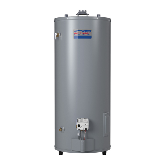
INSTALLING YOUR GAS WATER HEATER Important Information About installed in accordance with Massachusetts Plumbing and Fuel Gas Code 248 CMR Section 2.00 and 5.00. This Water Heater A data plate identifying your water heater can be found next to the gas control valve/thermostat. When referring to your This gas water heater was manufactured to voluntary water heater, always have the information listed on the data... -
Page 4: Location Requirements
and require replacement of the entire water heater. Note: Not following these instructions and/or an inadequate air supply can cause the Flame Guard Safety System to disable the water heater. Please make required installation and venting/air supply changes prior to resetting the system (see "Combustion Air Supply and Ventilation"... - Page 5 IMPORTANT: Thewaterheater s hould belocated Figure 1A in anareawhere leakage ofthetankor connections Air-moving Devices willnotresultindamage totheareaadjacent tothe waterheater o r tolower floorsofthestructure. Due tothenormal c orrosive a ctionofthewater, t hetank willeventually l eakafteranextended periodoftime. Alsoanyexternal plumbing leak,including thosefrom improper installation, maycause earlyfailure ofthetank Exhaust duetocorrosion if notrepaired.
-
Page 6: Gas Supply
Gas Supply Figure Gas Piping Manual Shut-off Valve'---._ Joint Ground Union Check with local utility for minimum height 3"M Explosion Hazard Drip Leg Use a new CSA approved gas supply line. Gas Pressure Install a shut-off valve. IMPORTANT: The gas supply pressure must not exceed the maximum supply pressure as stated on the water heater's data Do not connect a natural gas water heater to... - Page 7 Table1 Natural G asPipeCapacity T able (Cu.Ft./Hr.) Capacity of gas pipe of different diameters and lengths in cu. ft. per hr. with pressure drop of 0.3 in. and specific gravity of 0.60 (natural gas). Nominal Iron Pipe Length of Pipe, Feet Size, in.
- Page 8 Unconfined Space Figure 4 12" maximum Opening Locations- Awater heater in an unconfined space uses indoor air for Confined Spaces combustion and requires at least 50 cubic feet for each 1,000 BTU/HR of the total input for all gas appliances. The ,F-1 table below shows a few examples of the minimum square Closet...
- Page 9 All Air from Outdoors Gable vent to outdoors Outdoor fresh air can be provided to a confined area either Install above directly or by the use of vertical and horizontal ducts. The fresh air can be taken from the outdoors or from crawl or insulation ,-..
-
Page 10: Combustion Air Supply And Ventilation
Figure 9 Draft hood Installation Alternative Opening Location Metal Screws (four provided) _Draft hood Confined ] sq. Inch "_ Space Per 3000 BTU/HR Sl°tJ Jacket top P" LSl°t Install the draft hood with the four screws provided. Vent Pipe Size It is important that you follow the guidelines in these instructions for sizing a vent pipe system. - Page 11 Chimney Connection Figure 10 Listed Lined Chimney Termination r_chimney IMPORTANT: Before connecting a vent to a chimney, Vent System make sure the chimney passageway is clear and free of obstructions. The chimney must be cleaned if previously 2 ft. minimum above any object withinlO used for venting solid fuel appliances or fireplaces.
-
Page 12: Water System Piping
Water System Piping After piping has been properly connected to the water heater, remove the aerator at the nearest hot water faucet. Open the hot water faucet and allow the tank to Piping Installation completely fill with water. To purge the lines of any ex- Piping, fittings, and valves should be installed according to cess air, keep the hot water faucet open for 3 minutes the installation drawing (Figure 13). - Page 13 Please notethefollowing: Closed System/Thermal Expansion • Thesystem shouldbeinstalled onlywithpiping thatis suitable forpotable (drinkable) watersuchas copper, CPVC, o r polybutylene. Thiswaterheater m ustnotbe installed usingironpiping or PVCwaterpiping. • Useonlypumps, v alves, o rfittings thatarecompatible withpotable water. • Useonlyfullflowballor gatevalves. T heuseof valves thatmaycauseexcessive r estriction t owaterflowis notrecommended.
-
Page 14: Temperature & Pressure Relief Valve
IMPORTANT: Only a new temperature and pressure relief Temperature and Pressure valve should be used with your water heater. Do not use an Relief Valve old or existing valve as it may be damaged or not adequate for the working pressure of the new water heater. Do not place any valve between the relief valve and the tank. -
Page 15: Special Applications
Special Applications Some jurisdictions may require a backflow preventer in the incoming cold water line. This may cause the temperature and pressure relief valve on the water heater Combination Space Heating/Potable to discharge or weep due to expansion of the heated water. Water System A diaphragm-type expansion tank suitable for potable... -
Page 16: Installation Checklist
Important Information About This Water Heater This gas water heater was manufactured to voluntary safety standards to reduce the likelihood of a flammable vapor ignition incident. The new technology used in meeting these standards makes this product more sensitive to installation errors. -
Page 17: Operating Your Water Heater
OPERATING YOUR WATER HEATER Lighting Instructions Read and understand these directions thoroughly before Explosion Hazard attempting to light or re-light the pilot. Make sure the viewport is not missing or damaged. (See Figure 23) Replace viewport if glass is missing Make sure the tank is completely filled with water before or damaged. - Page 18 Burner Flames Checking the Draft Inspect the burner flames through the viewport. Flames should be very small with a blue haze and small amounts of yellow or orange at the edges. After several minutes Burn Hazard of operation, the burner screen may glow red. If large flames are observed at any time, shut-off unit and call a Do not touch vent.
- Page 19 IMPORTANT: Adjusting the thermostat past the 120°F bar Water Temperature Regulation on the temperature dial will increase the risk of scald injury. Hot water can produce first degree burns within: Table 4: Time for 1st Time for Water Permanent Burns Temperature °F Degree Burn 2nd &...
-
Page 20: Operating The Temperature Control System
Operating the Temperature Control System Status Light Codes Figure 19B: Status Codes Normal Flashes: List of status codes are shown • 0 Flashes Indicates Control Off/Pilot Out. at top of gas control valve/thermostat • 1 Flash Indicates Normal Operation. • Continuous Light indicates the gas control valve/thermostat is shutting down. -
Page 21: Operational Conditions
Operational Conditions A temperature limit switch or ECO (Energy Cut Off) sensor located in the gas control valve\thermostat is used to shut off the water heater if the water temperature exceeds 189°F (87°C). Condensation The Diagnostic Status Light will flash a code indicating Moisture from the products of combustion condenses on the tank surface and the outside jacket of the water heater and an "Overheat Failure"... - Page 22 MAINTENANCE OF YOUR WATER HEATER Draining and Flushing Temperature and Pressure Relief Valve It is recommended that the tank be drained and flushed every 6 months to remove sediment which may build up during operation. The water heater should be drained if being shut down during freezing temperatures.
- Page 23 Natural Gas Burner (Ultra Low Nox) Replacement Parts Check the burner to see if it is dirty or clogged. The burner IMPORTANT: The following maintenance procedures are may be cleaned with soft paint brush (Figure 24). Do not for the Flame Guard Safety System components and use a wire brush or any tool that may damage the burner should be performed by a qualified person.
- Page 24 External Inspection & Cleaning of the Replacing the Pilot/Thermopile Assembly Remove the burner assembly as directed previously. Flame-trap Lift the retainer clip straight up from the back of Although not likely to occur, if debris collects on the flame- the manifold component block (using a fiat-blade trap, use a vacuum, compressed air, or a soft bristle brush screwdriver), then remove the manifold component to remove it.
- Page 25 Replacing the Burner Door Assembly Figure Combustion Chamber Explosion Hazard Tighten both burner door screws Door Gasket securely. Figure 28B Close-up inside view of the combustion chamber Remove any fiberglass between gasket and combustion chamber. Replace viewport if glass is missing or damaged.
- Page 26 Removing and Replacing the Gas may result. Do not insert any sharp objects into the inlet or outlet connections. Damage to the gas control Control Valve/Thermostat valve/thermostat may result. Gas Control Valve/Thermostat: Removing the Gas Control Valve/Thermostat: To replace the gas control valve/thermostat, reassemble Turn the gas control/temperature knob to the "OFF"...
- Page 27 PROBLEM POSSIBLE CAUSE(S) CORRECTIVE ACTION PILOT WILL NOT LIGHT OR ECO switch open Replace gas control valve/thermostat 10. Clean, locate source and correct REMAIN LIT (continued) 10. Pilot line or orifice clogged 11. Non-functioning thermopite 11. Replace thermopite 12. Air for combustion obstructed 12.
- Page 28 STATUS LIGHT CODE TROUBLESHOOTING CHART LED STATUS PROBLEM CORRECTIVE ACTION 0 FLASHES (LED NOT LIT) Pilot light is not tit. Not enough Follow the lighting instructions on the front of the power (millivolts) to keep it lit. water heater and record any diagnostic codes. See Diagnostic Status Light Code section.
- Page 29 PILOT LIGHT TROUBLESHOOTING CHART Section A: Pilot light will not light (new installation). Section C: Pilot light will not remain lit. Check for insufficient combustion air. m Is the manual gas shut-off valve, •lTurn the manual gas shut-off valve to located in the supply line to the IN NO _lthe on position and follow the lighting...
-
Page 30: Repair Parts Illustration
REPAIR PARTS ILLUSTRATION When ordering repair parts always give the following information: Model, serial, and product number Type of gas Item number Parts description Repair Parts List Item Parts Description DRAFT HOOD REDUCER RING - SOME MODELS FLUE BAFFLE HEAT TRAP (COLD) - SOME MODELS HEAT TRAP (HOT) - SOME MODELS COLD WATER DIP TUBE ANODE ROD... - Page 31 Listed Parts Kits and Illustrations Item 12: Pilot assembly kit, which contains the pilot, electrode, and thermopile (Natural Gas) Item 13: Burner Door assembly, which contains the burner, gasket, door, pilot tube, manifold component block with retainer clip, temperature sensor, and pilot assembly. (Natural Gas/Low Nox) Item 14: Contains manifold component block and retainer clip Item 15:...
- Page 32 Copyright © 2010 American Water Heater Company. All Rights Reserved. Printed in the U.S.