Table of Contents
Advertisement
Quick Links
WARNING: If the information in these
instructions is not followed exactly, a fire
or explosion may result causing property
damage, personal injury or death.
Do not store or use gasoline or other
flammable vapors and liquids in the
vicinity of this or any other appliance.
WHAT TO DO IF YOU SMELL GAS
•
Do not try to light any appliance.
•
Do not touch any electrical switch;
do not use any phone in your
building.
•
Immediately call your gas supplier
from a neighbor's phone. Follow
the gas supplier's instructions.
•
If you cannot reach your gas
supplier, call the fire department.
Installation and service must be performed
by a qualified installer, service agency or
the gas supplier.
INSTALLER:
•
AFFIX THESE INSTRUCTIONS TO OR ADJACENT
TO THE WATER HEATER.
OWNER:
•
RETAIN THESE INSTRUCTIONS AND WARRANTY
FOR FUTURE REFERENCE. RETAIN THE ORIGINAL
RECEIPT AS PROOF OF PURCHASE.
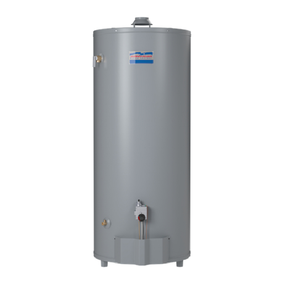
Ultra Low Nox
Gas Water Heater
with the Flame Guard™
Safety System
Installation
Instructions and
Use & Care Guide
To obtain technical, warranty, or service assistance during or after
the installation of this water heater, visit our website at:
http://www.americanwaterheater.com
or call toll free
1-800-999-9515
When calling for assistance, please have the following
information ready:
1.
Model number
2.
7 digit product number
3.
Serial number
4.
Date of installation
5.
Place of purchase
Table of Contents ......................................................
318935-003
LOW LEAD
CONTENT
2
June 2012
1
Advertisement
Table of Contents

Related Manuals for American Water Heater Ultra Low Nox


Summary of Contents for American Water Heater Ultra Low Nox
- Page 1 Ultra Low Nox Gas Water Heater with the Flame Guard™ Safety System WARNING: If the information in these Installation instructions is not followed exactly, a fire or explosion may result causing property Instructions and damage, personal injury or death. Do not store or use gasoline or other Use &...
-
Page 2: Table Of Contents
WATER HEATER SAFETY Your safety and the safety of others are very important. We have provided many important safety messages in this manual and on your appliance. Always read and obey all safety messages. This is the safety alert symbol. This symbol alerts you to potential hazards that can kill or hurt you and others. -
Page 3: Water Heater Safety
INSTALLING YOUR GAS WATER HEATER Important Information About installed in accordance with Massachusetts Plumbing and Fuel Gas Code 248 CMR Section 2.00 and 5.00. This Water Heater A data plate identifying your water heater can be found next to the gas control valve/thermostat. When referring to your This gas water heater was manufactured to voluntary water heater, always have the information listed on the data safety standards to reduce the likelihood of a flammable... -
Page 4: Location Requirements
and require replacement of the entire water heater. Note: WARNING Not following these instructions and/or an inadequate air supply can cause the Flame Guard™ Safety System to disable the water heater. Please make required installation and venting/air supply changes prior to resetting the system (see “Combustion Air Supply and Ventilation”... -
Page 5: Clearances And Accessibility
IMPORTANT: The water heater should be located Figure 1A Air-moving in an area where leakage of the tank or connections Devices will not result in damage to the area adjacent to the water heater or to lower floors of the structure. Due to the normal corrosive action of the water, the tank will eventually leak after an extended period of time. -
Page 6: Gas Supply
Gas Supply Figure 3 Gas Piping Manual Gas Shut-off Valve WARNING Ground Joint Union Check with local utility for minimum height 3” Minimum Explosion Hazard Sediment Trap Use a new CSA approved gas supply line. Gas Pressure Install a shut-off valve. IMPORTANT: The gas supply pressure must not exceed the maximum supply pressure as stated on the water heater’s data Do not connect a natural gas water heater to... -
Page 7: Combustion Air Supply And Ventilation
Combustion Air Supply and Combustion air must be free of acid-forming chemicals such as sulfur, fluorine, and chlorine. These elements are Ventilation found in aerosol sprays, detergents, bleaches, cleaning solvents, air fresheners, paint, and varnish removers, WARNING refrigerants, and many other commercial and household products. -
Page 8: Unconfined Space
Unconfined Space Figure 4 12” maximum Opening Locations- A water heater in an unconfined space uses indoor air for Confined Spaces combustion and requires at least 50 cubic feet for each 1,000 BTU/HR of the total input for all gas appliances. The table below shows a few examples of the minimum square Closet footage (area) required for various BTU/HR inputs. -
Page 9: All Air From Outdoors
All Air from Outdoors Gable vent to outdoors Outdoor fresh air can be provided to a confined area either Install above directly or by the use of vertical and horizontal ducts. The insulation fresh air can be taken from the outdoors or from crawl or attic spaces that freely communicate with the outdoors. -
Page 10: Vent Pipe System
Figure 9 Draft hood Inst allation Sheet Metal Screws (four provided) Alternative Opening Draft hood Legs Location Legs 1 sq. Inch Confined Slot Slot Per 3000 BTU/HR Space Jacket top Install the draft hood with 3”- 4” Draft Hood the four screws provided. Combination Sheet Metal Screws (four provided) Draft hood... -
Page 11: Chimney Connection
Chimney Connection Listed Lined Chimney IMPORTANT: Before connecting a vent to a chimney, make sure the chimney passageway is clear and free of 2 ft. minimum above any obstructions. The chimney must be cleaned if previously object within10 ft. used for venting solid fuel appliances or fireplaces. Also horizontally 3 ft. -
Page 12: Water System Piping
Water System Piping 7. After piping has been properly connected to the water heater, remove the aerator at the nearest hot water Piping Installation faucet. Open the hot water faucet and allow the tank to completely fill with water. To purge the lines of any ex- Piping, fittings, and valves should be installed according to cess air, keep the hot water faucet open for 3 minutes the installation drawing (Figure 13). - Page 13 Closed System/Thermal Expansion Please note the following: • The system should be installed only with piping that is WARNING suitable for potable (drinkable) water such as copper, CPVC, or polybutylene. This water heater must not be installed using iron piping or PVC water piping. •...
-
Page 14: Temperature & Pressure Relief Valve
Temperature and Pressure IMPORTANT: Only a new temperature and pressure relief valve should be used with your water heater. Do not use an Relief Valve old or existing valve as it may be damaged or not adequate for the working pressure of the new water heater. Do not WARNING place any valve between the relief valve and the tank. -
Page 15: Special Applications
Special Applications Some jurisdictions may require a backflow preventer in the incoming cold water line. This may cause the Combination Space Heating/Potable temperature and pressure relief valve on the water heater to discharge or weep due to expansion of the heated water. Water System A diaphragm-type expansion tank suitable for potable water will normally eliminate this weeping condition. -
Page 16: Installation Checklist
Important Information About This Water Heater This gas water heater was manufactured to voluntary safety standards to reduce the likelihood of a flammable vapor ignition incident. The new technology used in meeting these standards makes this product more sensitive to installation errors. -
Page 17: Operating Your Water Heater
OPERATING YOUR WATER HEATER Lighting Instructions WARNING Read and understand these directions thoroughly before Explosion Hazard attempting to light or re-light the pilot. Make sure the viewport is not missing or damaged. (See Figure 23) Make Replace viewport if glass is missing sure the tank is completely filled with water before lighting or damaged. -
Page 18: To Turn Off Gas To Appliance
FOR YOUR SAFETY READ BEFORE LIGHTING WARNING: If you do not follow these instructions exactly, a fire or explosion may result causing property damage, personal injury or loss of life. A. This appliance has a pilot which is lighted by a C. -
Page 19: Emergency Shut Down
Checking the Draft Burner Flames Inspect the burner flames through the viewport. Flames WARNING should be very small with a blue haze and small amounts of yellow or orange at the edges. After several minutes Burn Hazard of operation, the burner screen may glow red. If large flames are observed at any time, shut-off unit and call a Do not touch vent. -
Page 20: Water Temperature Regulation
Water Temperature Regulation IMPORTANT: Adjusting the thermostat past the 120°F bar on the temperature dial will increase the risk of scald injury. WARNING Hot water can produce first degree burns within: Table 4: Time for Time for 1st Water Permanent Burns Degree Burn Temperature °F 2nd &... -
Page 21: Operating The Temperature Control System
Operating the Temperature Operational Conditions Control System Condensation Moisture from the products of combustion condenses on Figure 19B: Status Codes the tank surface and the outside jacket of the water heater and forms drops of water which may fall onto the burner or List of status codes are shown other hot surfaces. - Page 22 the gas supply to the burner if poor combustion is sensed NOTE: This rod may reduce but not eliminate water odor (caused by a blocked vent or insufficient combustion air). If problems. The water supply system may require special the gas control valve/thermostat shuts off the gas supply, filtration equipment from a water conditioning company to check the diagnostic flash code and refer to the “Status successfully eliminate all water odor problems.
-
Page 23: Maintenance Of Your Water Heater
MAINTENANCE OF YOUR WATER HEATER Draining and Flushing Temperature and Pressure Relief Valve It is recommended that the tank be drained and flushed every 6 months to remove sediment which may build up WARNING during operation. The water heater should be drained if being shut down during freezing temperatures. -
Page 24: Removing The Burner Door Assembly
Replacement Parts 6. Grasp the manifold tube and push down slightly to free the manifold, pilot tube, and thermopile. IMPORTANT: The following maintenance procedures are 7. Carefully remove the burner door assembly from the for the Flame Guard™ Safety System components and burner compartment. - Page 25 Replacing the Pilot/Thermopile Assembly 7. Use the screw removed earlier to attach the new pilot/ thermopile assembly to the burner door assembly. 1. Remove the burner assembly. See Removing the Burner NOTE: Remove the pilot nut included with the new Door Assembly Section.
-
Page 26: Replacing The Burner Door Assembly
Cleaning the Combustion Chamber and Figure 28 Pilot/Thermopile Assembly Flame-trap Pilot Tube (50K Models) (Ferrule Nut Igniter 1. Follow procedure outlined in “Removing the Burner Connector Not Shown) Door Assembly”. Thermopile Pilot/Thermopile Connectors 2. Use a vacuum cleaner/shop vac to remove all loose Assembly Thermopile debris in the combustion chamber (Figure 30A). -
Page 27: Piezoelectric Igniter System
Piezoelectric Igniter System if the door gasket does not create a seal between the burner door and the combustion chamber. The piezoelectric igniter system consists of the igniter 6. Reconnect the manifold tubing (3/4” wrench), pilot button, electrode, and wire. The pilot is ignited by an tubing (7/16”... -
Page 28: Troubleshooting Charts
Removing and Replacing the Gas Gas Control Valve/Thermostat: To replace the gas control valve/thermostat, reassemble Control Valve/Thermostat in reverse order. When replacing the gas control valve/ thermostat, thread a 4” section of gas pipe into the inlet and Removing the Gas Control Valve/Thermostat: use it to turn the gas control valve/thermostat (clockwise.) 1. - Page 29 PROBLEM POSSIBLE CAUSE(S) CORRECTIVE ACTION PILOT WILL NOT LIGHT OR ECO switch open Replace gas control valve/thermostat REMAIN LIT (continued) 10. Pilot line or orifice clogged 10. Clean, locate source and correct 11. Non-functioning thermopile 11. Replace thermopile 12. Air for combustion obstructed 12.
- Page 30 STATUS LIGHT CODE TROUBLESHOOTING CHART LED STATUS PROBLEM CORRECTIVE ACTION 0 FLASHES (LED NOT LIT) Pilot light is not lit. Not enough Follow the lighting instructions on the front of the power (millivolts) to keep it lit. water heater and record any diagnostic codes. See Diagnostic Status Light Code section.
- Page 31 PILOT LIGHT TROUBLESHOOTING CHART Section A: Pilot light will not light (new installation). Section C: Pilot light will not remain lit. Check for insufficient combustion air. Is the manual gas shut-off valve, Turn the manual gas shut-off valve to located in the supply line to the the on position and follow the lighting water heater, in the on position? Are the combustion air supply and ventilation openings...
-
Page 32: Repair Parts Illustration
REPAIR PARTS ILLUSTRATION When ordering repair parts always give the following information: 1. Model, serial, and product number 2. Type of gas 3. Item number 4. Parts description Repair Parts List Item Parts Description DRAFT HOOD DRAFT HOOD (50K Models only) REDUCER RING - SOME MODELS FLUE BAFFLE HEAT TRAP (COLD) - SOME MODELS... -
Page 33: Listed Parts Kits And Illustrations
Listed Parts Kits and Illustrations Item 12A: Pilot assembly kit, which contains the pilot, electrode, and thermopile (Natural Gas) Item 12B: Pilot assembly kit (50K Models), which contains the pilot, electrode, and thermopile (Natural Gas) Item 13A: Burner Door assembly, which contains the burner, gasket, door, pilot tube, manifold component block with retainer clip, temperature sensor, and pilot assembly. - Page 34 NOTES...
- Page 35 NOTES...
- Page 36 Copyright © 2012 American Water Heater Company. All Rights Reserved. Printed in the U.S.