Table of Contents
Advertisement
HEATERS
TM
WARNING:
If the information
in these
instructions
is not followed
exactly,
a fire
or explosion
may result
causing
property
damage,
personal
injury or death.
Do not store
or use gasoline
or other
flammable
vapors
and liquids
in the
vicinity
of this or any other appliance.
WHAT TO DO IF YOU SMELL GAS
•
Do not try to light any appliance.
+
Do not touch
any electrical
switch;
do not use any phone in your
building.
+
Immediately
call your gas supplier
from a neighbor's
phone. Follow
the
gas supplier's
instructions.
+
If you cannot
reach your
gas
supplier,
call the fire department.
Installation
and service
must be performed
by a qualified
installer, service
agency
or
the gas supplier.
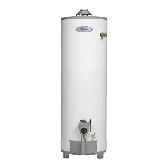
Gas Water Heater
with the Flame Lock TM
Safety System
Installation
Instructions and
Use & Care Guide
To obtain technical, warranty, or service assistance during or
after the installation of this water heater, call toll free:
1-877-817-6750
When
calling
for assistance,
please
have the following
information
ready:
I.
Model number
2.
7 Digit product number
3.
Serial number
4.
Date of installation
Table of Contents
......................................................
2
6510233
September
2001
Advertisement
Table of Contents

Related Manuals for Whirlpool FG1H5040T3NOV


Summary of Contents for Whirlpool FG1H5040T3NOV
-
Page 1: Water Heater Safety
HEATERS Gas Water Heater with the Flame Lock TM Safety System Installation WARNING: If the information in these instructions is not followed exactly, a fire Instructions and or explosion may result causing property damage, personal injury or death. Use & Care Guide Do not store or use gasoline or other... -
Page 2: Table Of Contents
Your safety and the safety of others are very important. We have provided many important safety messages in this manual and on your appliance. Always read and obey all safety messages. This is the safety alert symbol. This symbol alerts you to potential hazards that can kill or hurt you and others. All safety messages will follow the safety alert symbol and either the word "DANGER"... -
Page 3: Installing Your Gas Water Heater
;TALL! EATE Consumer information Unpacking the Water Heater This water heater is design-certified by CSA International as a Category I, non-direct vented water heater which takes its combustion air either from the Excessive Weight Hazard installation area or from air ducted to the unit from the people Use two or more... -
Page 4: Location Requirements
Location Requirements Carbon Dioxide Poisoning Hazard Do not install in a mobile home. Doing so can result in death or carbon monoxide poisoning. The Flame Lock safety system is designed to reduce the risk of flammable vapor related fires. The patented system protects your family by trapping the burning vapors within the water heater combustion chamber through the special flame-trap. - Page 5 Important:Thewaterheater s hould belocated inan Figure 1 areawhereleakage ofthetankor connections will not Air Moving Devices result i ndamage to theareaadjacent t othewater heater o r tolower floorsof thestructure. Duetothe normal c orrosive a ctionofthewater,thetankwill eventually l eakafteranextended period oftime.A suitable metal d rainpanshould beinstalled underthe waterheater a sshown below, t ohelpprotect t he Exhaust property f romdamage whichmayoccurfrom...
-
Page 6: Gas Supply
Gas Supply Figure 3 Gas Piping Manual Gas c:::3 Sh ut-off Valve Ground Joint _---_ Union Check with local utility for min. height 3 in. min. Explosion Hazard Use a new AGA or CSA approved Drip leg" supply line. Pressure Install a shut-off valve. -
Page 7: Combustion Air Supply And Ventilation
Table 1 Natural Gas Pipe Capacity Table (Cu. Ft./hr) Capacity of gas pipe of different diameters and lengths in cu. ft. per hr. with pressure drop of 0.3 in. and specific gravity of 0.60 (natural gas). Nominal Iron Pipe Length of Pipe, Feet Size, in. - Page 8 Figure 4 Unconfined Space 12" inches maximum Opening Locations- ...1.._ Confined Spaces A water heater in an unconfined space uses indoor air for combustion and requires at least 50 cubic feet for each 1,000 BTUH of the total input for all gas Closet appliances.
- Page 9 Gable vent All Air from Outdoors to outdoors Outdoor fresh air can be provided to a confined area Install above either directly or by the use of vertical and horizontal ducts. The fresh air can be taken from the outdoors or insulation from crawl or attic spaces that freely communicate with the outdoors.
- Page 10 Vent Pipe System Vent Pipe Size This water heater uses a non-direct, single-pipe vent The vent pipe must be installed according to all local and state codes or in absence of local and state codes system to remove exhaust gases created by the burning of fossil fuels.
- Page 11 Chimney Connection Certified Lined Figure 10 Chimney Termination Important: Before connecting a vent to a chimney, Vent System _himney make sure the chimney passageway is clear and free of 2 ft. min. above any object obstructions. The chimney must be cleaned if within 10 ft, previously used for venting solid fuel appliances or Horizontally...
-
Page 12: Water System Piping
After piping has been properly connected to the Water System Piping water heater, remove the aerator at the nearest hot water faucet. Open the hot water faucet and allow Piping Installation the tank to completely fill with water. To purge the lines of any excess air, keep the hot water faucet Piping, fittings, and valves should be installed according open for 3 minutes after a constant flow of water is... - Page 13 Please notethefollowing: Closed System/Thermal Expansion DONOTinstall t hiswaterheater w ithironpiping. Periodic discharge of the temperature and pressure Thesystem should beinstalled onlywithnewpiping relief valve may be due to thermal expansion in a thatis suitable forpotable (drinkable) watersuchas closed water supply system. The water utility supply copper, C PVC, o r polybutylene.
- Page 14 Important: Only a new temperature and pressure relief Temperature and Pressure valve should be used with your water heater. Do not Relief Valve use an old or existing valve as it may be damaged or not adequate for the working pressure of the new water heater.
- Page 15 Some jurisdictions may require a backflow preventer in Special Applications the incoming cold water line. This may cause the temperature and pressure relief valve on the water Combination Space Heating/Potable heater to discharge or weep due to expansion of the Water System heated water.
-
Page 16: Installation Checklist
installation Checklist Water Heater Location Vent Pipe System • Centrally located with the water piping system. • Drafthood properly installed. Located as close to the gas piping and vent pipe • Vent connectors securely fastened with screws and system as possible. supported properly to maintain 6 inch clearance. -
Page 17: Operating Yourwater Heater
G YOUR EATE Lighting instructions LP.G. (Bottled Propane) Models Liquefied Petroleum Gas is over 50% heavier than air Read and understand these directions thoroughly and in the occurrence of a leak in the system the gas will before attempting to light or re-light the pilot. Make sure settle at floor level. - Page 18 Checking the Draft Water Temperature Regulation Burn Hazard Do not touch vent. Doing so can result burns. After successfully lighting the water heater, allow the unit to operate for 15 minutes and check the drafthood Water temperature over 125°F can cause relief opening for proper draft.
-
Page 19: Operational Conditions
which is designed to disable the gas valve in the event Operational Conditions of excessive combustion chamber temperatures or a flammable vapor ignition. If the fuse opens, the water Condensation heater cannot be used unless the thermocouple is replaced by a qualified service technician. Contact the Moisture from the products of combustion condenses Product Service and Support Department for service... -
Page 20: Maintenance Of Yourwater Heater
NTENANCE OF YOU WATER EATER Draining and Flushing Temperature and Pressure Relief Valve It is recommended that the tank be drained and flushed every 6 months to remove sediment which may buildup during operation. The water heater should be drained if being shut down during freezing temperatures. - Page 21 Replacement Parts Figure Burner Assembly Removal Piezo The following maintenance procedures are for the Gas Valve igniter Thermostat Flame Lock safety system components and should be performed by a qualified service Thermocouple technician. Pilot Tube Replacement parts may be ordered through your Manifold plumber or the local distributor.
-
Page 22: Natural/L.p. Gas Burner
Natural Gas Burner (Low Nox) Replacing the Thermocouple Take off the burner by removing the two(2) screws Important: Use only a factory authorized Flame located underneath the burner. Lock safety system thermocouple for replacement. Check the burner to see if it is dirty or clogged. The Remove the manifold assembly as directed burner may be cleaned with soap and hot water previously. - Page 23 Cleaning the Combustion Chamber Bracket and Flame-trap Follow procedure outlined in "Removing the Manifold Assembly". Use a vacuum cleaner/shop vac to remove all loose debris in the combustion chamber and flame-trap. See Figure 26. Reassemble following the procedure under IIHII Figure 26 _"...
- Page 24 Piezoelectric Igniter System Removing and Replacing the Gas Control Valve/Thermostat The piezoelectric igniter system is part of the Flame Lock safety system and consists of the igniter button, Important: The gas control valve/thermostat is a electrode and wire. The pilot is ignited by an electric standard valve with a left hand thread thermocouple spark generated when the igniter button is pressed.
-
Page 25: Troubleshooting Chart
Flame Lock Safety System Operational Checklist Manifold gasket properly sealed. Viewport not damaged or cracked. Flame-trap free of debris and undamaged. Two piece wire connector properly installed. No leaks at pilot and manifold connection. Manifold door screws securely tightened. TROUBLESHOOTING CHART PROBLEM CORRECTIVE ACTION... - Page 26 TROUBLESHOOTING CHART (continued) PROBLEM POSSIBLE CAUSE(S} CORRECTIVE ACTION SLOWHOTWATER RECOVERY Insufficientsecondaryair Provideventilationto waterheater.Checkflue way Fluebaffleand burner Cleanflue, locatesourceandcorrect Flueclogged Lowgas pressure Checkwith gas utilitycompany Impropercalibration Replacethermostat Thermostat s et too low Turntemperaturedialto desiredsetting Waterheatertoo small Installadequateheater Wrongpipingconnections Correctpiping-diptube mustbe incold inlet Wastedhot water Advise customer Excessivewaterpressure...
-
Page 27: Repair Parts Illustration
PARTS ILLUSTRAT! location for top T&P Alternate anode ___ Anode location for side T & P When ordering repair parts always give the following information: Model, serial, and product number Type of gas Item number Parts description Repair Parts List item Parts Description DRAFTHOOD... -
Page 28: Part Kits And Illustrations
Contains two piece wire connector with retainer clip, and pilot assembly. item 18: Contains manifold door gasket. item 19: Contains viewport. Item #11 Item #14 Item Item #15 Item #17 Item #18 Item #1_9 Printed in the U.S. ®2001 Whirlpool "All rights reserved." 7MRegistered trademark/TM Trademark of Whirlpool, U.S.A.