Table of Contents
Advertisement
Advertisement
Table of Contents

Related Manuals for Asus P7P55D PREMIUM


Summary of Contents for Asus P7P55D PREMIUM
- Page 1 P7P55D Premium...
- Page 2 Product warranty or service will not be extended if: (1) the product is repaired, modified or altered, unless such repair, modification of alteration is authorized in writing by ASUS; or (2) the serial number of the product is defaced or missing.
-
Page 3: Table Of Contents
Contents Notices ........................vii Safety information ....................viii About this guide ......................ix P7P55D Premium specifications summary ............. xi Chapter 1: Product introduction Welcome! ....................1-1 Package contents..................1-1 Special features..................1-2 1.3.1 Product highlights................ 1-2 1.3.2 ASUS Xtreme Design—Hybrid Processor ........1-3 1.3.3... - Page 4 BIOS setup Knowing BIOS .................... 3-1 Updating BIOS .................... 3-1 3.2.1 ASUS Update utility..............3-2 3.2.2 ASUS EZ Flash 2 utility ............... 3-4 3.2.3 ASUS CrashFree BIOS 3 utility........... 3-5 BIOS setup program .................. 3-6 3.3.1 BIOS menu screen ..............3-6 3.3.2...
- Page 5 Security ..................3-31 Tools menu ....................3-33 3.9.1 ASUS O.C. Profile ..............3-33 3.9.2 AI NET 2 ..................3-34 3.9.3 ASUS EZ Flash 2 ..............3-34 3.9.4 Express Gate ................3-35 3.9.5 ID LED ..................3-35 3.10 Exit menu ....................3-36...
- Page 6 High Definition Audio utility ..........4-8 ® ASUS Unique Overclocking Utility—TurboV EVO ........4-9 4.4.1 Using ASUS TurboV ..............4-9 4.4.2 Using ASUS TurboV Auto Tuning Mode ........4-10 4.4.3 Using ASUS Turbo Key ............. 4-11 RAID configurations ................4-12 4.5.1 RAID definitions ................ 4-12 4.5.2...
-
Page 7: Notices
Complying with the REACH (Registration, Evaluation, Authorisation, and Restriction of Chemicals) regulatory framework, we published the chemical substances in our products at ASUS REACH website at http://green.asus.com/english/REACH.htm. DO NOT throw the motherboard in municipal waste. This product has been designed to enable proper reuse of parts and recycling. -
Page 8: Safety Information
Safety information Electrical safety • To prevent electrical shock hazard, disconnect the power cable from the electrical outlet before relocating the system. • When adding or removing devices to or from the system, ensure that the power cables for the devices are unplugged before the signal cables are connected. If possible, disconnect all power cables from the existing system before you add a device. -
Page 9: About This Guide
Where to find more information Refer to the following sources for additional information and for product and software updates. ASUS websites The ASUS website provides updated information on ASUS hardware and software products. Refer to the ASUS contact information. Optional documentation Your product package may include optional documentation, such as warranty flyers, that may have been added by your dealer. -
Page 10: Conventions Used In This Guide
Conventions used in this guide To ensure that you perform certain tasks properly, take note of the following symbols used throughout this manual. DANGER/WARNING: Information to prevent injury to yourself when trying to complete a task. CAUTION: Information to prevent damage to the components when trying to complete a task. -
Page 11: P7P55D Premium Specifications Summary
* Hyper DIMM support is subject to the physical characteristics of individual CPUs. Some hyper DIMMs only support one DIMM per channel. Please refer to Memory QVL for details. ** Refer to www.asus.com or this user manual for the Memory QVL (Qualified Vendors Lists) Expansion Slots 2 x PCI Express 2.0 x16 slots (single at x16 or dual at x8 / x8... - Page 12 - ASUS CrashFree BIOS 3 - ASUS EZ Flash 2 - ASUS My Logo 2 - Multi-language BIOS ASUS Q-Design ASUS Q-Design: - ASUS Q-LED (CPU, DRAM, VGA, Boot Device LED) - ASUS Q-Slot - ASUS Q-DIMM ASUS Exclusive Precision Tweaker 2: Overclocking Features - vCore: Adjustable CPU voltage at 0.00625V increment...
- Page 13 P7P55D Premium specifications summary Internal I/O Connectors 2 x USB connectors support additional 4 USB ports 1 x IDE connector 1 x COM connector 6 x SATA 3.0Gb/s connectors (blue) 2 x SATA 6.0Gb/s connectors (gray) 1 x CPU Fan connector...
-
Page 15: Chapter 1: Product Introduction
® The motherboard delivers a host of new features and latest technologies, making it another standout in the long line of ASUS quality motherboards! Before you start installing the motherboard, and hardware devices on it, check the items in your package with the list below. -
Page 16: Special Features
Green ASUS This motherboard and its packaging comply with the European Union’s Restriction on the use of Hazardous Substances (RoHS). This is in line with the ASUS vision of creating environment-friendly and recyclable products/packagings to safeguard consumers’ health while minimizing the impact on the environment. -
Page 17: Asus Xtreme Design-Hybrid Processor
ASUS Xtreme Design—Hybrid OS Express Gate SSD Instant Online! Instant Fun! Express Gate SSD is an ASUS exclusive OS that provides you with quick access to the Internet and key applications before entering the Windows OS. Refer to page 3-35 and 4-7 ®... -
Page 18: Asus Exclusive Features
ASUS EPU System Level Energy Saving The new ASUS EPU—the world’s first power saving engine, has been upgraded to a new 6 engine version, which provides total system power savings by detecting current PC loadings and intelligently moderating power in real-time. With auto phase switching for components... -
Page 19: Asus Crystal Sound
With these technologies, you may experience a better home-theater audio with ease. ASUS EZ DIY ASUS EZ DIY feature collection provides you easy ways to install computer components, update the BIOS or back up your favorite settings. ASUS Onboard Switch... -
Page 20: Asus Mylogo2
Freely share and distribute favorite overclocking settings. The motherboard features the ASUS O.C. Profile that allows users to conveniently store or load multiple BIOS settings. The BIOS settings can be stored in the CMOS or a separate file, giving users freedom to share and distribute their favorite overclocking settings. -
Page 21: Chapter 2: Hardware Information
Before you install or remove any component, ensure that the ATX power supply is switched off or the power cord is detached from the power supply. Failure to do so may cause severe damage to the motherboard, peripherals, or components. ASUS P7P55D Premium... -
Page 22: Motherboard Overview
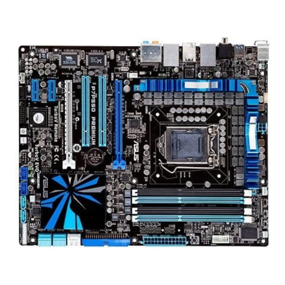
Motherboard overview 2.2.1 Motherboard layout Refer to 2.7 Connectors for more information about rear panel connectors and internal connectors. Chapter 2: Hardware information... -
Page 23: Layout Contents
2-24 TPM connector (20-1 pin TPM) 2-34 IEEE 1394a port connector (10-1 pin IE1394_2) 2-36 Digital audio connector (4-1 pin SPDIF_OUT) 2-38 Optical drive audio connector (4-pin CD) 2-35 Front panel audio connector (10-1 pin AAFP) 2-38 ASUS P7P55D Premium... -
Page 24: Placement Direction
2.2.3 Placement direction When installing the motherboard, ensure that you place it into the chassis in the correct orientation. The edge with external ports goes to the rear part of the chassis as indicated in the image below. 2.2.4 Screw holes Place nine screws into the holes indicated by circles to secure the motherboard to the chassis. -
Page 25: Central Processing Unit (Cpu)
Contact your retailer immediately if the PnP cap is missing, or if you see any damage to the PnP cap/socket contacts/motherboard components. ASUS will shoulder the cost of repair only if the damage is shipment/ transit-related. - Page 26 Lift the load lever in the direction of the arrow until the load plate is completely lifted. Load plate Remove the PnP cap from the CPU socket. PnP cap Position the CPU over the socket, ensuring that the gold triangle is on the bottom-left corner of the socket, and then CPU notches fit the socket alignment keys into the CPU...
- Page 27 Close the load plate (A), and then push down the load lever (B), ensuring that the front edge of the load plate slides under the retention lock (C). Insert the load lever under the retention tab. ASUS P7P55D Premium...
-
Page 28: Installing The Cpu Heatsink And Fan
2.3.2 Installing the CPU heatsink and fan The Intel LGA1156 processor requires a specially designed heatsink and fan assembly to ® ensure optimum thermal condition and performance. • When you buy a boxed Intel ® processor, the package includes the CPU fan and heatsink assembly. -
Page 29: Uninstalling The Cpu Heatsink And Fan
Rotate each fastener counterclockwise. Pull up two fasteners at a time in a diagonal sequence to disengage the heatsink and fan assembly from the motherboard. Carefully remove the heatsink and fan assembly from the motherboard. ASUS P7P55D Premium... -
Page 30: System Memory
System memory 2.4.1 Overview The motherboard comes with four Double Data Rate 3 (DDR3) Dual Inline Memory Modules (DIMM) sockets. A DDR3 module has the same physical dimensions as a DDR2 DIMM but is notched differently to prevent installation on a DDR2 DIMM socket. DDR3 modules are developed for better performance with less power consumption. -
Page 31: Memory Configurations
• According to Intel spec definition, DDR3-1600 is supported for one DIMM per channel only. ASUS exclusively provides two DDR3-1600 DIMM support for each memory channel. • According to Intel CPU spec, DIMM voltage below 1.65V is recommended to protect the CPU. - Page 32 P7P55D Premium Motherboard Qualified Vendors Lists (QVL) DDR3-1067MHz capability for CPU at 2.66, 2.8 and 2.93GHz DIMM socket support Timing (Optional) Vendor Part No. Size Chip Brand Chip NO. Voltage Dimm(Bios) CORSAIR CM3X1024-1066C7 Heat-Sink Package • • • Crucial CT12864BA1067.8SFD...
- Page 33 P7P55D Premium Motherboard Qualified Vendors Lists (QVL) DDR3-1333MHz capability for CPU at 2.66, 2.8 and 2.93GHz (continued) DIMM socket support Chip Timing Vendor Part No. Size Chip NO. Voltage (Optional) Brand Dimm(Bios) ELPIDA EBJ21UE8BAW0-DJ-E ELPIDA J1108BABG-DJ-E 9(1333-9-9-9-24) • • •...
- Page 34 P7P55D Premium Motherboard Qualified Vendors Lists (QVL) DDR3-1333MHz capability for CPU at 2.66, 2.8 and 2.93GHz (continued) DIMM socket support Chip Timing Vendor Part No. Size Chip NO. Voltage (Optional) Brand Dimm(Bios) Patriot PVT33G1333ELK Heat-Sink Package 9-9-9-24(1066-7-7-7-20) 1.65 • •...
- Page 35 P7P55D Premium Motherboard Qualified Vendors Lists (QVL) DDR3-1600MHz capability for CPU at 2.66GHz (continued) DIMM socket support Chip Timing Vendor Part No. Size Chip NO. Voltage (Optional) Brand Lable(Bios) Patriot PVS34G1600LLK(XMP) 4GB(Kit of 2) DS N/A Heat-Sink Package 7-7-7-20(1066-7-7-7-20) •...
- Page 36 P7P55D Premium Motherboard Qualified Vendors Lists (QVL) DDR3-1625MHz capability for CPU at 2.66GHz DIMM socket support Chip Timing (Optional) Vendor Part No. Size Chip NO. Voltage Brand Dimm(Bios) KINGSTON KHX13000D3LLK2/2GN(EPP) 2GB(Kit of 2) Heat-Sink Package • • • KINGSTON KHX13000D3LLK2/2GX(XMP) 2GB(Kit of 2) Heat-Sink Package •...
- Page 37 P7P55D Premium Motherboard Qualified Vendors Lists (QVL) DDR3-1866MHz capability for CPU at 2.66GHz DIMM socket support Chip Timing (Optional) Vendor Part No. Size Chip NO. Voltage Brand Dimm(Bios) CORSAIR TR3X3G1866C9D(XMP) 3GB(Kit of 3) SS Heat-Sink Package 9-9-9-24(1866-9-9-9-24) 1.65 • •...
- Page 38 Hyper DIMM support is subject to the physical characteristics of individual CPUs. • According to Intel spec definition, DDR3-1600 is supported for one DIMM per channel only. ASUS exclusively provides two DDR3-1600 DIMM support for each memory channel. • According to Intel CPU spec, CPUs with a core frequency of 2.66G support the maximum DIMM frequency of up to DDR3-1333.
-
Page 39: Installing A Dimm
Press the retaining clip outward to unlock the DIMM. Support the DIMM lightly with your fingers when pressing the retaining clip. The DIMM might get damaged when it flips out with extra force. Remove the DIMM from the socket. ASUS P7P55D Premium 2-19... -
Page 40: Expansion Slots
Expansion slots In the future, you may need to install expansion cards. The following subsections describe the slots and the expansion cards that they support. Ensure to unplug the power cord before adding or removing expansion cards. Failure to do so may cause you physical injury and damage motherboard components. -
Page 41: Interrupt Assignments
– – – – – Onboard ATA controller – – shared – – – – – 1394 controller – – shared – – – – – HD Audio – – – – – – shared – ASUS P7P55D Premium 2-21... -
Page 42: Pci Slots
2.5.4 PCI slots The PCI slots support cards such as a LAN card, SCSI card, USB card, and other cards that comply with PCI specifications. Refer to the figure below for the location of the slot. 2.5.5 PCI Express 2.0 x1 slots (2.5GT/s) This motherboard supports PCI Express x1 network cards, SCSI cards and other cards that comply with the PCI Express specifications. - Page 43 We recommend that you provide sufficient power when running CrossFireX™ or SLI™ mode. Refer to page 2-39 for details. • Connect a chassis fan to the motherboard connector labeled CHA_FAN1/2 when using multiple graphics cards for better thermal environment. Refer to page 2-37 for details. ASUS P7P55D Premium 2-23...
-
Page 44: Onboard Switches
Onboard switches Onboard switches allow you to fine-tune performance when working on a bare or open- case system. This is ideal for overclockers and gamers who continually change settings to enhance system performance. Power-on switch The motherboard comes with a power-on switch that allows you to power up or wake up the system. - Page 45 BIOS default settings. A messgae will appear during POST reminding you that the BIOS has been restored to its default settings. • We recommend that you download and update to the latest BIOS version from the ASUS website at www.asus.com after using the MemOK! function. ASUS P7P55D Premium 2-25...
- Page 46 CPU / IMC / DRAM overvoltage setting switches (OV_DRAM, OV_IMC, OV_CPU) These switches allow you to enable or disable the advanced CPU, Integrated Memory Controller (IMC), and DRAM overvoltage settings in BIOS. Read the following information before you change the switch settings. The LED color indicates the voltage setting status of CPU, IMC and DRAM.
-
Page 47: Connectors
7. Clear CMOS switch *and **: Refer to the tables on the next page for LAN port and audio port definitions. Press the Clear CMOS switch to clear BIOS setup information only when the system hangs due to overclocking. ASUS P7P55D Premium 2-27... -
Page 48: Audio I/O Connections
*LAN port LED indications ACT/LINK SPEED Activity Link LED Speed LED Status Description Status Description No link 10 Mbps connection ORANGE Linked ORANGE 100 Mbps connection LAN port BLINKING Data activity GREEN 1 Gbps connection ** Audio 2, 4, 6, 8, or 10-channel configuration Headset Port 4-channel... - Page 49 Connect to Stereo / 2.1-channel Speakers Connect to 4.1-channel Speakers Connect to 5.1-channel Speakers ASUS P7P55D Premium 2-29...
- Page 50 Connect to 7.1-channel Speakers Connect to 9.1-channel Speakers 2-30 Chapter 2: Hardware information...
-
Page 51: Internal Connectors
This prevents incorrect insertion when you connect the IDE cable. • Use the 80-conductor IDE cable for Ultra DMA 133/100/66 IDE devices. If any device jumper is set as “Cable-Select”, ensure that all other device jumpers have the same setting. ASUS P7P55D Premium 2-31... - Page 52 Intel P55 Serial ATA connectors (7-pin SATA 1-6) ® These connectors are for the Serial ATA signal cables for Serial ATA hard disk drives and optical disc drives. If you installed Serial ATA hard disk drives, you can create a RAID 0, 1, 5, and 10 configuration with the Intel Matrix Storage Technology through the onboard Intel ®...
- Page 53 ATA hard disk drives. The Serial ATA RAID feature is available only if you are using Windows XP SP2 or later versions. ® When using hot-plug and NCQ, set the Marvell 9123 Controller item in the BIOS to • [AHCI Mode]. Refer to section 3.6.3 Onboard Devices Configuration for details. ASUS P7P55D Premium 2-33...
- Page 54 Ensure to install the TurboV Remote driver from the motherboard support DVD. Refer to section 4.2 Support DVD information for details. Refer to section 4.3.4 ASUS EPU-6 Engine and 4.4 ASUS Unique Overclocking • Utlity—TurboV EVO for related software details.
- Page 55 Never connect a 1394 cable to the USB connectors. Doing so will damage the motherboard! You can connect the front panel USB cable to the ASUS Q-Connector (USB, blue) first, and then install the Q-Connector (USB) to the USB connector onboard if your chassis supports front panel USB ports.
- Page 56 IEEE 1394a port connector (10-1 pin IE1394_2) This connector is for an IEEE 1394a port. Connect the IEEE 1394a module cable to this connector, then install the module to a slot opening at the back of the system chassis. Never connect a USB cable to the IEEE 1394a connector. Doing so will damage the motherboard! The IEEE 1394a module is purchased separately.
- Page 57 These are not jumpers! Do not place jumper caps on the fan connectors! • Only the CPU_FAN, CHA_FAN 1 and CHA_FAN 2 connectors support the ASUS FAN Xpert feature. • If you install two VGA cards, we recommend that you plug the rear chassis fan cable to the motherboard connector labeled CHA_FAN1 or CHA_FAN2 for better thermal environment.
- Page 58 Digital audio connector (4-1 pin SPDIF_OUT) This connector is for an additional Sony/Philips Digital Interface (S/PDIF) port(s). Connect the S/PDIF Out module cable to this connector, then install the module to a slot opening at the back of the system chassis. The S/PDIF module is purchased separately.
- Page 59 • If you are uncertain about the minimum power supply requirement for your system, refer to the Recommended Power Supply Wattage Calculator at http://support.asus. com/PowerSupplyCalculator/PSCalculator.aspx?SLanguage=en-us for details. • If you want to use two or more high-end PCI Express x16 cards, use a PSU with 1000W power or above to ensure the system stability.
-
Page 60: System Panel Connector
System panel connector (20-8 pin PANEL) This connector supports several chassis-mounted functions. • System power LED (2-pin PLED) This 2-pin connector is for the system power LED. Connect the chassis power LED cable to this connector. The system power LED lights up when you turn on the system power, and blinks when the system is in sleep mode. -
Page 61: Asus Q-Connector (System Panel)
2.7.4. ASUS Q-Connector (system panel) Use the ASUS Q-Connector to connect/disconnect the chassis front panel cables. Connect the front panel cables to the ASUS Q-Connector. Refer to the labels on the Q-Connector to know the detailed pin definitions, and then match them to their respective front panel cable labels. -
Page 62: Onboard Leds
Onboard LEDs POST State LEDs POST State LEDs check key components (CPU, DRAM, VGA card, and HDD) in sequence during motherboard booting process. If an error is found , the LED next to the error device will continue lighting until the problem is solved. This user-friendly design provides an intuitional way to locate the root problem within a second. -
Page 63: Starting Up For The First Time
BIOS setting. Pressing the power switch for more than four seconds lets the system enter the soft-off mode regardless of the BIOS setting. Refer to section 3.7 Power Menu in Chapter 3 for details. ASUS P7P55D Premium 2-43... - Page 64 2-44 Chapter 2: Hardware information...
-
Page 65: Chapter 3: Bios Setup
Refer to the corresponding sections for details on these utilities. Save a copy of the original motherboard BIOS file to a USB flash drive in case you need to restore the BIOS in the future. Copy the original motherboard BIOS using the ASUS Update utility. -
Page 66: Asus Update Utility
3.2.1 ASUS Update utility The ASUS Update is a utility that allows you to manage, save, and update the motherboard BIOS in Windows environment. The ASUS Update utility allows you to: ® • Save the current BIOS file • Download the latest BIOS file from the Internet •... - Page 67 Auto Select. Click Next. Next. Follow the onscreen instructions to complete the update process. The ASUS Update utility is capable of updating itself through the Internet. Always update the utility to avail all its features. Updating the BIOS through a BIOS file...
-
Page 68: Asus Ez Flash 2 Utility
ASUS EZ Flash 2 utility The ASUS EZ Flash 2 feature allows you to update the BIOS without having to use a DOS-based utility. The EZ Flash 2 utility is built in the BIOS chip so it is accessible by pressing <Alt>... -
Page 69: Asus Crashfree Bios 3 Utility
The BIOS file in the motherboard support DVD may be older than the BIOS file published on the ASUS official website. If you want to use the newer BIOS file, download the file at support.asus.com and save it to a USB flash drive. -
Page 70: Bios Setup Program
BIOS setup program A BIOS Setup program is provided for BIOS item modification. When you start up the computer, the system provides you with the opportunity to run this program. Press <Del> during the Power-On Self-Test (POST) to enter the Setup utility. Otherwise, POST continues with its test routines. -
Page 71: Navigation Keys
<Page Up> / <Page Down> keys to Pop-up window display the other items on the screen. 3.3.9 General help At the top right corner of the menu screen is a brief description of the selected item. ASUS P7P55D Premium... -
Page 72: Main Menu
Main menu When you enter the BIOS Setup program, the Main menu screen appears, giving you an overview of the basic system information. You can also set the system time and date and BIOS language in this menu. Refer to 3.3.1 BIOS menu screen for information on the menu screen items and how to navigate through them. - Page 73 32-bit double word transfer to the processor. This makes more efficient use of the PCI bus as fewer transactions are needed for the transfer of a particular amount of data. [Disabled] Disables this function. ASUS P7P55D Premium...
-
Page 74: Storage Configuration
3.4.2 Storage Configuration The Storage Configuration menu allows you to configure your storage devices. Select an item then press <Enter> to display the submenu. BIOS SETUP UTILITY Main Set [Compatible Mode] Storage Configuration when Legacy OS (i.e. SATA Configuraton [Enhanced] WIN ME, 98, NT4.0, MS Configure SATA as [IDE]... -
Page 75: System Information
BIOS SETUP UTILITY Main BIOS Information BIOS Version : 0204 BIOS Build Date : 07/24/09 EC BIOS Version : MBEC-0027 Processor Type : Genuine Intel(R) CPU @ 2.13GHz Speed : 2139MHz System Memory Usable Size : 1016MB ASUS P7P55D Premium 3-11... -
Page 76: Ai Tweaker Menu
Ai Tweaker menu The Ai Tweaker menu items allow you to configure overclocking-related items. Be cautious when changing the settings of the Ai Tweaker menu items. Incorrect field values can cause the system to malfunction. The configuration options for this chapter vary depending on the CPU and DIMM model you installed on the motherboard. - Page 77 D.O.C.P. D.O.C.P. • When using DIMMs with a frequncy higher than the Intel CPU spec, use this ASUS ® exclusive DRAM O.C. Profile function to overclock the DRAM. • Adjust BCLK frequency to obtain a better performance after applying the D.O.C.P function.
-
Page 78: Xtreme Phase Full Power Mode
3.5.5 Xtreme Phase Full Power Mode [Auto] [Auto] Automatic configuration. [Enabled] Enables Full Power Mode to ensure the best CPU overclocking performance. The following two items appear only when you set the Ai Overclock Tuner item to [Manual], [D.O.C.P.] or [X.M.P.]. BCLK Frequency [XXX] Allows you to adjust the Internal Base Clock (BCLK). - Page 79 Configuration options: [Auto] [1 DRAM Clock] – [8 DRAM Clock] DRAM WRITE to READ Delay(DR) [Auto] Configuration options: [Auto] [1 DRAM Clock] – [8 DRAM Clock] DRAM WRITE to READ Delay(SR) [Auto] Configuration options: [Auto] [10 DRAM Clock] – [22 DRAM Clock] ASUS P7P55D Premium 3-15...
-
Page 80: Cpu Differential Amplitude
DRAM READ to WRITE Delay(DD) [Auto] Configuration options: [Auto] [2 DRAM Clock] – [14 DRAM Clock] DRAM READ to WRITE Delay(DR) [Auto] Configuration options: [Auto] [2 DRAM Clock] – [14 DRAM Clock] DRAM READ to WRITE Delay(SR) [Auto] Configuration options: [Auto] [2 DRAM Clock] – [14 DRAM Clock] DRAM READ to READ Delay(DD) [Auto] Configuration options: [Auto] [2 DRAM Clock] –... -
Page 81: Imc Voltage
According to Intel CPU spec, DIMM voltage below 1.65V is recommended to protect the CPU. 3.5.14 CPU PLL Voltage [Auto] Allows you to set the CPU PLL voltage. The values range from 1.8V to 2.1V with a 0.1V interval. ASUS P7P55D Premium 3-17... -
Page 82: Pch Voltage
3.5.15 PCH Voltage [Auto] Allows you to set the Platform Controller Hub voltage. The values range from 1.05V to 1.15V with a 0.10V interval. The values of the IMC Voltage, DRAM Voltage, and CPU PLL Voltage items are • labeled in different color, indicating the risk levels of high voltage settings. Refer to the table below for details. -
Page 83: Advanced Menu
CPU TM function [Enabled] Execute-Disable Bit Capability [Enabled] Intel(R) HT Technology [Enabled] Active Processor Cores [All] A20M [Disabled] Intel(R) SpeedStep(TM) Tech [Enabled] Intel(R) Turbo Mode tech [Enabled] Intel(R) C-STATE Tech [Disabled] v02.61 (C)Copyright 1985-2009, American Megatrends, Inc. ASUS P7P55D Premium 3-19... - Page 84 CPU Ratio Setting [Auto] Allows you to adjust the ratio between CPU Core Clock and BCLK Frequency. Use the <+> and <-> keys to adjust the value. The valid value ranges differently according to your CPU model. C1E Support [Enabled] [Enabled] Enables the C1E support function.
-
Page 85: Uncore Configuration
Memory Remap Feature [Enabled] [Disabled] Do not allow remapping of memory. [Enabled] Allows for the segment of system memory that was previously overwritten by PCI devices to be remapped above the total physical memory. ASUS P7P55D Premium 3-21... -
Page 86: Onboard Devices Configuration
3.6.3 Onboard Devices Configuration BIOS SETUP UTILITY Advanced Onboard Devices Configuration Options HDA Controller [Enabled] Front Panel Type [HD Audio] Enabled Realtek LAN1 [Enabled] Disabled LAN Boot ROM [Disabled] Realtek LAN2 [Enabled] LAN Boot ROM [Disabled] Onboard 1394 Controller [Enabled] J-Micron PATA Controller [Enabled] Serial Port1 Address... -
Page 87: Usb Configuration
USB controller legacy mode is enabled. If no USB device is detected, the legacy USB support is disabled. BIOS EHCI Hand-off [Enabled] [Disabled] Disables the function. [Enabled] Enables the support for operating systems without an EHCI hand-off feature. ASUS P7P55D Premium 3-23... -
Page 88: Pcipnp
3.6.5 PCIPnP The PCIPnP menu items allow you to change the advanced settings for PCI/PnP devices. BIOS SETUP UTILITY Advanced Advanced PCI/PnP Settings NO: lets the BIOS configure all the WARNING: Setting wrong values in below sections devices in the may cause system to malfunction. -
Page 89: Power Menu
Allows BIOS to switch off some power at S5 state to get system ready for the EuP requirement. When set to [Enabled], power for WOL, WO_USB, audio and onboard LEDs will be switched off at S5 state. ASUS P7P55D Premium 3-25... -
Page 90: Apm Configuration
3.7.6 APM Configuration BIOS SETUP UTILITY Power APM Configuration <Enter> to select whether or not to Restore on AC Power Loss [Power Off] restart the system Power On By RTC Alarm [Disabled] after AC power loss. Power On By External Modems [Disalbed] Power On By PCI Devices [Disabled]... -
Page 91: Hardware Monitor
[Standard] Sets to [Standard] to make the CPU fan automatically adjust depending on the CPU temperature. [Silent] Sets to [Silent] to minimize the fan speed for quiet CPU fan operation. [Turbo] Set to [Turbo] to achieve maximum CPU fan speed. ASUS P7P55D Premium 3-27... - Page 92 Chassis Q-Fan Control [Disabled] [Disabled] Disables the Chassis Q-Fan control feature. [Enabled] Enables the Chassis Q-Fan control feature. Chassis Fan Profile [Standard] This item appears only when you enable the Chassis Q-Fan Control feature and allows you to set the appropriate performance level of the chassis fan. [Standard] Sets to [Standard] to make the chassis fan automatically adjust depending on the chassis temperature.
-
Page 93: Boot Menu
Configuration options: [Removable Dev.] [Hard Drive] [ATAPI CD-ROM] [Disabled] • To select the boot device during system startup, press <F8> when ASUS Logo appears. • To access Windows OS in Safe Mode, do any of the following: ®... -
Page 94: Boot Settings Configuration
Disables the full screen logo display feature. [Enabled] Enables the full screen logo display feature. Set this item to [Enabled] to use the ASUS MyLogo 2™ feature. AddOn ROM Display Mode [Force BIOS] [Force BIOS] The third-party ROM messages will be forced to display during the boot sequence. -
Page 95: Security
(RTC) RAM. See section 2.7.1 Rear panel connectors for information on how to erase the RTC RAM. After you have set a supervisor password, the other items appear to allow you to change other security settings. ASUS P7P55D Premium 3-31... - Page 96 BIOS SETUP UTILITY Boot Security Settings <Enter> to change password. Supervisor Password : Installed <Enter> again to User Password : Installed disabled password. Change Supervisor Password User Access Level [Full Access] Change User Password Clear User Password Password Check [Setup] User Access Level [Full Access] This item allows you to select the access restriction to the Setup items.
-
Page 97: Tools Menu
<Enter> to display the submenu. BIOS SETUP UTILITY Main Ai Tweaker Advanced Power Boot Tools Exit ASUS O.C. Profile AI NET 2 ASUS EZ Flash 2 Express Gate [Auto] Enter OS Timer [10 Seconds] Reset User Data [No] ID LED [Enabled] Select Screen ←→... -
Page 98: Ai Net 2
3.9.3 ASUS EZ Flash 2 Allows you to run ASUS EZ Flash 2. When you press <Enter>, a confirmation message appears. Use the left/right arrow key to select between [Yes] or [No], then press <Enter> to confirm your choice. Check section 3.2.2 ASUS EZ Flash 2 utility for details. -
Page 99: Express Gate
3.9.4 Express Gate [Auto] Allows you to enable or disable the ASUS Express Gate feature. The ASUS Express Gate feature is a unique instant-on environment that provides quick access to the Internet browser and Skype. Configuration options: [Disabled] [Enabled] [Auto] Enter OS Timer [10 Seconds] Sets countdown duration that the system waits at the Express Gate’s first screen... -
Page 100: Exit Menu
3.10 Exit menu The Exit menu items allow you to load the optimal or failsafe default values for the BIOS items, and save or discard your changes to the BIOS items. BIOS SETUP UTILITY Main Ai Tweaker Advanced Power Boot Tools Exit Exit Options... -
Page 101: Chapter 4: Software Support
The contents of the support DVD are subject to change at any time without notice. Visit the ASUS website at www.asus.com for updates. 4.2.1 Running the support DVD Place the support DVD into the optical drive. -
Page 102: Obtaining The Software Manuals
The software manual files are in Portable Document Format (PDF). Install the Adobe ® Acrobat Reader from the Utilities menu before opening the files. ® Click the Manual tab. Click ASUS Motherboard Utility Guide from the manual list on the left. The Manual folder of the support DVD appears. Double-click the folder of your selected software. -
Page 103: Software Information
Launching PC Probe II Install PC Probe II from the motherboard support DVD. Launch PC Probe II by clicking Start > All Programs > ASUS > PC Probe II > PC Probe II v1.xx.xx. The PC Probe II main window appears. -
Page 104: Asus Ai Suite
Launching AI Suite Install AI Suite from the motherboard support DVD. Launch AI Suite by clicking Start > All Programs > ASUS > AI Suite > AI Suite v1.xx. xx. The AI Suite main window appears. The AI Suite icon appears in the Windows notification area. -
Page 105: Asus Fan Xpert
4.3.3 ASUS Fan Xpert Asus Fan Xpert allows you to adjust both the CPU and chassis fan speeds according to different ambient temperatures and your PC’s system loading. The various fan profiles offer flexible controls of fan speeds to achieve a quiet and cool system environment. -
Page 106: Asus Epu-6 Engine
4.3.4 ASUS EPU-6 Engine ASUS EPU-6 Engine is an energy-efficient tool that satisfies different computing needs. This utility provides four modes that you can select to enhance system performance or save power: Turbo Mode • Medium Power Saving Mode •... -
Page 107: Asus Express Gate Ssd
Skype, or other Express Gate SSD applications. It’s a built-in utility, you can enjoy it without installation. Notices about ASUS Express Gate SSD • ASUS Express Gate SSD supports SATA devices in IDE mode only. See chapter 3 for BIOS setup details. • ASUS Express Gate SSD supports SATA devices connected to motherboard chipset-controlled onboard SATA ports only. -
Page 108: Via ® High Definition Audio Utility
VIA HD Audio Deck for Windows XP Display panel and volume control Minimize button Configuration options Control settings window Refer to the software manual in the support DVD or visit the ASUS website at www.asus.com for detailed software configuration. Chapter 4: Software support... -
Page 109: Asus Unique Overclocking Utility-Turbov Evo
If the TurboV EVO is correctly installed, you will find the TurboV EVO icon on the Windows notification area. Click on the icon to display the TurboV EVO control panel. Refer to the software manual in the support DVD or visit the ASUS website at www.asus.com for detailed software configuration. 4.4.1... -
Page 110: Using Asus Turbov Auto Tuning Mode
4.4.2 Using ASUS TurboV Auto Tuning Mode The Auto Tuning Mode allows smart auto-overclocking. Follow the instructions below to let TurboV EVO detect and overclock your system. Click the Auto Tuning tab and then click Start. You can also click More Setting... -
Page 111: Using Asus Turbo Key
4.4.3 Using ASUS Turbo Key ASUS Turbo Key allows the user to set a group of hot-keys into physical overclocking buttons. After the easy setup, Turbo Key can boost performances without interrupting ongoing work or games—with just one touch! If the TurboV EVO is correctly installed, you will find the TurboV EVO icon on the Windows notification area. -
Page 112: Raid Configurations
RAID configurations The motherboard comes with the Intel P55 chipset that allows you to configure Serial ATA ® hard disk drives as RAID sets. The motherboard supports the following RAID configurations: RAID 0, RAID 1, RAID 10 and RAID 5. •... -
Page 113: Installing Serial Ata Hard Disks
None defined. Physical Disks: Port Drive Model Serial # Size Type/Status(Vol ID) ST3160812AS 9LS0HJA4 149.0GB Non-RAID Disk ST3160812AS 9LS0F4HL 149.0GB Non-RAID Disk ST3160812AS 3LS0JYL8 149.0GB Non-RAID Disk ST3160812AS 9LS0BJ5H 149.0GB Non-RAID Disk [↑↓]-Select [ESC]-Exit [ENTER]-Select Menu ASUS P7P55D Premium 4-13... -
Page 114: Creating A Raid Volume
The navigation keys at the bottom of the screen allow you to move through the menus and select the menu options. The RAID BIOS setup screens shown in this section are for reference only and may not exactly match the items on your screen. The utility supports maximum four hard disk drives for RAID configuration. - Page 115 WARNING: ALL DATA ON SELECTED DISKS WILL BE LOST. Are you sure you want to create this volume? (Y/N): Press <Y> to create the RAID volume and return to the main menu, or <N> to go back to the CREATE VOLUME menu. ASUS P7P55D Premium 4-15...
- Page 116 Deleting a RAID set Take caution when deleting a RAID set. You will lose all data on the hard disk drives when you delete a RAID set. To delete a RAID set From the utility main menu, select 2. Delete RAID Volume and press <Enter>. The following screen appears.
-
Page 117: Creating A Raid Driver Disk
Go to the Make Disk menu, and then click Intel AHCI/RAID Driver to create an Intel ® RAID driver disk. Select USB floppy disk drive as the destination disk. Follow the succeeding screen instructions to complete the process. Write-protect the floppy disk to avoid a computer virus infection. ASUS P7P55D Premium 4-17... -
Page 118: Installing The Raid Driver During Windows ® Os Installation
4.6.3 Installing the RAID driver during Windows OS installation ® To install the RAID driver for Windows ® During the OS installation, the system prompts you to press the F6 key to install third- party SCSI or RAID driver. Press <F6>, and then insert the floppy disk with RAID driver into the USB floppy disk drive. - Page 119 Browse the contents of the RAID driver disk to locate the file txtsetup.oem. Double-click the file. A window appears, allowing you to select the program for opening the oem file. Use Notepad to open the file. ASUS P7P55D Premium 4-19...
- Page 120 Find the [HardwareIds.scsi.iaAHCI_PCH] and [HardwareIds.scsi.iastor_8R9R10RDOPCH] sections in the txtsetup.oem file. Type the following line to the bottom of the two sections: id = “USB\VID_xxxx&PID_xxxx”, “usbstor” [HardwareIds.scsi.iaAHCI_PCH] id= “PCI\VEN_8086&DEV_3A22&CC_0106”,”iaStor” id= “USB\VID_03EE&PID_6901”, “usbstor” [HardwareIds.scsi.iaStor_8R9R10RDOPCH] id= “PCI\VEN_8086&DEV_3A22&CC_0106”,”iaStor” id= “USB\VID_03EE&PID_6901”, “usbstor” Add the same line to both sections. The VID and PID vary with different vendors.
-
Page 121: Chapter 5: Multiple Gpu Technology Support
PCIEX16 slots. If your motherboard has more than two PCIEX16 slots, refer to Chapter 2 in this user manual for the locations of the PCIEX16 slots recommended for multi-graphics card installation. Ensure that the cards are properly seated on the slots. ASUS P7P55D Premium... -
Page 122: Installing The Device Drivers
Align and firmly insert the CrossFireX bridge connector to the goldfingers on each graphics card. Ensure that the connector is firmly in place. Goldfingers CrossFireX bridge (bundled with graphics cards) Connect two independent auxiliary power sources from the power supply to the two graphics cards separately. -
Page 123: Enabling The Ati ® Crossfirex™ Technology
In the Catalyst Control Center window, click Graphics Settings > CrossFireX > Configure. From the Graphics Adapter list, select the graphics card to act as the display GPU. Select Enable CrossFireX. Click Apply, and then click OK to exit the window. ASUS P7P55D Premium... -
Page 124: Nvidia ® Sli™ Technology
NVIDIA SLI™ technology ® The motherboard supports the NVIDIA SLI™ (Scalable Link Interface) technology that ® allows you to install multi-graphics processing units (GPU) graphics cards. Follow the installation procedures in this section. 5.2.1 Requirements • In SLI mode, you should have two identical SLI-ready graphics cards that are NVIDIA ®... -
Page 125: Installing The Device Drivers
You can launch the NVIDIA Control Panel by the following two methods. Right click on the empty space of the Windows desktop ® and select NVIDIA Control Panel. The NVIDIA Control Panel window appears (See Step B5). ASUS P7P55D Premium... - Page 126 If you cannot see the NVIDIA Control Panel item in step (A), select Personalize. From the Personalization window, select Display Settings. From the Display Settings dialog box, click Advanced Settings. Chapter 5: Multiple GPU technology support...
- Page 127 Start the NVIDIA Control Panel. The NVIDIA Control Panel window appears. Enabling SLI settings From the NVIDIA Control Panel window, select Set SLI Configuration. Click Enable SLI and set the display for viewing SLI rendered content. When done, click Apply. ASUS P7P55D Premium...
- Page 128 Chapter 5: Multiple GPU technology support...