Table of Contents
Advertisement
Advertisement
Table of Contents

Related Manuals for Asus P7P55 LX JOOYON SI


Summary of Contents for Asus P7P55 LX JOOYON SI
- Page 1 P7P55 LX...
- Page 2 Product warranty or service will not be extended if: (1) the product is repaired, modified or altered, unless such repair, modification of alteration is authorized in writing by ASUS; or (2) the serial number of the product is defaced or missing.
-
Page 3: Table Of Contents
Welcome! ..................1-1 Package contents ................. 1-1 Special features ................1-1 1.3.1 Product highlights ............1-1 1.3.2 Innovative ASUS features ..........1-2 Before you proceed ..............1-5 Motherboard overview ..............1-6 1.5.1 Placement direction ............1-6 1.5.2 Screw holes ..............1-6 1.5.3... - Page 4 Chapter 2: BIOS information Managing and updating your BIOS ..........2-1 2.1.1 ASUS Update utility ............2-1 2.1.2 ASUS EZ Flash 2 ............2-2 2.1.3 ASUS CrashFree BIOS ........... 2-3 2.1.4 ASUS BIOS Updater ............2-3 BIOS setup program ..............2-6 2.2.1...
- Page 5 Boot Settings Configuration .......... 2-25 2.7.3 Security ................. 2-25 Tools menu ................. 2-26 2.8.1 ASUS O.C. Profile ............2-27 2.8.2 AI NET 2................ 2-27 2.8.3 Express Gate ..............2-27 2.8.4 ASUS EZ Flash 2 ............2-28 Exit menu ..................2-28...
-
Page 6: Notices
Complying with the REACH (Registration, Evaluation, Authorisation, and Restriction of Chemicals) regulatory framework, we published the chemical substances in our products at ASUS REACH website at http://green.asus.com/english/REACH.htm. DO NOT throw the motherboard in municipal waste. This product has been designed to enable proper reuse of parts and recycling. -
Page 7: Safety Information
Safety information Electrical safety • To prevent electric shock hazard, disconnect the power cable from the electric outlet before relocating the system. • When adding or removing devices to or from the system, ensure that the power cables for the devices are unplugged before the signal cables are connected. If possible, disconnect all power cables from the existing system before you add a device. -
Page 8: About This Guide
Operation safety • Before installing the motherboard and adding devices on it, carefully read all the manuals that came with the package. • Before using the product, ensure that all cables are correctly connected and the power cables are not damaged. If you detect any damage, contact your dealer immediately. •... -
Page 9: Conventions Used In This Guide
Refer to the following sources for additional information and for product and software updates. ASUS websites The ASUS website provides updated information on ASUS hardware and software products. Refer to the ASUS contact information. Optional documentation Your product package may include optional documentation, such as warranty flyers, that may have been added by your dealer. -
Page 10: P7P55 Lx Specifications Summary
Extreme Memory Profile (XMP) ® ** Hyper DIMM support is subject to the physical characteristics of individual CPUs. *** Refer to www.asus.com for the latest Memory QVL (Qualified Vendors List). **** When you install a total memory of 4GB or more, Windows 32-bit operating system may only recognize less ®... - Page 11 ASUS Exclusive Features: - MemOK! - ASUS EPU - Express Gate ASUS Quiet Thermal Solution: - ASUS Fanless Design: Stylish Heatsink Solution - ASUS Fan Xpert ASUS EZ DIY: - ASUS Q-DIMM - ASUS O.C. Profile - ASUS CrashFree BIOS 3...
- Page 12 BIOS 16 Mb Flash ROM, AMI BIOS, PnP, DMI 2.0, WfM 2.0, SM BIOS 2.5, ACPI 2.0a, Multi-language BIOS, ASUS EZ Flash 2, ASUS CrashFree BIOS 3 Manageability WfM 2.0, DMI 2.0, WOL by PME, WOR by PME, PXE Accessories 1 x Ultra DMA 133/100/66 cable 2 x Serial ATA 3.0Gb/s cables...
-
Page 13: Chapter 1: Product Introduction
® The motherboard delivers a host of new features and latest technologies, making it another standout in the long line of ASUS quality motherboards! Before you start installing the motherboard, and hardware devices on it, check the items in your package with the list below. -
Page 14: Innovative Asus Features
1.3.2 Innovative ASUS features Turbo Key ASUS Turbo Key allows you to turn the PC power button into a physical overclocking button. After the easy setup, Turbo Key can boost performances without interrupting ongoing work or games—with just one touch! -
Page 15: Asus Turbov
Internet and key applications before entering the Windows ® • ASUS Express Gate supports installation on SATA HDDs, USB HDDs and flash drives with at least 1.2GB free disk space. When installing it on USB HDDs or flash drives, connect the drives to the motherboard USB port before turning on the computer. -
Page 16: Asus Mylogo2
BIOS file using the bundled support DVD or USB flash disk that contains the latest BIOS file. ASUS EZ Flash 2 ASUS EZ Flash 2 is a utility that allows you to update the BIOS without using an OS-based utility. ASUS AI NET2... -
Page 17: Before You Proceed
ON, in sleep mode, or in soft-off mode. This is a reminder that you must shut down the system and unplug the power cable before removing or plugging in any motherboard component. The illustration below shows the location of the onboard LED. SB_PWR P7P55 LX Standby Power Powered Off P7P55 LX Onboard LED ASUS P7P55 LX... -
Page 18: Motherboard Overview
Motherboard overview Before you install the motherboard, study the configuration of your chassis to ensure that the motherboard fits into it. Ensure that you unplug the power cord before installing or removing the motherboard. Failure to do so can cause you physical injury and damage motherboard components. 1.5.1 Placement direction When installing the motherboard, ensure that you place it into the chassis in the correct... -
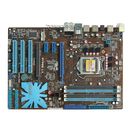
Page 19: Motherboard Layout
1-27 SPDIF_OUT) DDR3 DIMM slots 1-13 Optical drive audio connector (4-pin CD) 1-25 IDE connector (40-1 pin PRI_EIDE) 1-25 Front panel audio connector (10-1 pin 1-24 AAFP) Onboard LED (SB_PWR) Serial port connector (10-1 pin COM1) 1-28 ASUS P7P55 LX... -
Page 20: Central Processing Unit (Cpu)
Contact your retailer immediately if the PnP cap is missing, or if you see any damage to the PnP cap/socket contacts/motherboard components. ASUS will shoulder the cost of repair only if the damage is shipment/transit-related. • Keep the cap after installing the motherboard. ASUS will process Return Merchandise Authorization (RMA) requests only if the motherboard comes with the cap on the LGA1156 socket. - Page 21 CPU notches. The CPU fits in only one correct orientation. DO NOT force the CPU into the socket to prevent bending Gold the connectors on the socket and triangle damaging the CPU! mark Alignment keys ASUS P7P55 LX...
- Page 22 Apply some Thermal Interface Material to the exposed area of the CPU that the heatsink will be in contact with, ensuring that it is spread in an even thin layer. Some heatsinks come with pre- applied thermal paste. If so, skip this step.
-
Page 23: Installing The Cpu Heatsink And Fan
The type of CPU heatsink and fan assembly may differ, but the installation steps and functions should remain the same. The illustration above is for reference only. ASUS P7P55 LX 1-11... -
Page 24: Uninstalling The Cpu Heatsink And Fan
Connect the CPU fan cable to the connector on the motherboard labeled CPU_FAN. CPU_FAN P7P55 LX P7P55 LX CPU fan connector Do not forget to connect the CPU fan connector! Hardware monitoring errors can occur if you fail to plug this connector. 1.6.3 Uninstalling the CPU heatsink and fan To uninstall the CPU heatsink and fan:... -
Page 25: System Memory
The figure illustrates the location of the DDR3 DIMM sockets: Channel Sockets Channel A DIMM_A1 and DIMM_A2 Channel B DIMM_B1 and DIMM_B2 P7P55 LX P7P55 LX 240-pin DDR3 DIMM sockets ASUS P7P55 LX 1-13... -
Page 26: Memory Configurations
1.7.2 Memory configurations You may install 512MB, 1GB, 2GB, and 4GB unbuffered non-ECC DDR3 DIMMs into the DIMM sockets. • You may install varying memory sizes in Channel A and Channel B. The system maps the total size of the lower-sized channel for the dual-channel configuration. Any excess memory from the higher-sized channel is then mapped for single-channel operation. - Page 27 7-7-7-24 1.9V • • • OCZ3G1600LV6GK 6144MB(Kit of 3) DS Heat-Sink Package 8-8-8-24 1.65V • • • Super Talent WA160UX6G9 6144MB(Kit of 3) DS Heat-Sink Package • • • Kingtiger KTG2G1600PG3 2048MB Heat-Sink Package • • ASUS P7P55 LX 1-15...
- Page 28 DDR3 1333 MHz capability Vendor Part No. Size Chip Chip NO. Voltage DIMM socket Brand support (optinal) A-Data AD31333001GOU 1024MB A-Data AD30908C8D-151C E0906 • • • A-Data AD31333G001GOU 3072MB(Kit of 3) SS Heat-Sink Package 8-8-8-24 1.65- • • • 1.85V A-Data AD31333002GOU 2048MB...
- Page 29 • Hyper DIMM support is subject to the physical characteristics of individual CPUs. • According to Intel spec definition, DDR3 1600+ is supported for one DIMM per channel only. ASUS exclusively provides two DDR3 1600+ DIMM support for each memory channel.
-
Page 30: Installing A Dimm
1.7.3 Installing a DIMM Ensure to unplug the power supply before adding or removing DIMMs or other system components. Failure to do so may cause severe damage to both the motherboard and the components. To install a DIMM DIMM notch Unlock a DIMM socket by pressing the retaining clip outward. -
Page 31: Expansion Slots
This motherboard has two PCI Express 2.0 x16 slots that support PCI Express x16 2.0 graphic cards complying with the PCI Express specifications. Refer to section 1.2 Motherboard Overview for the location of the expansion slots. ASUS P7P55 LX 1-19... -
Page 32: Clear Rtc Ram
• In single VGA card mode, use the PCIe 2.0 x16_1 slot (blue) for a PCI Express x16 graphics card to get better performance. • We recommend that you provide sufficient power when running CrossFireX™ mode. • Connect a chassis fan to the motherboard connector labeled CHA_FAN when using multiple graphics cards for better thermal environment. - Page 33 • The USB device wake-up feature requires a power supply that can provide 500mA on the +5VSB lead for each USB port; otherwise, the system would not power up. • The total current consumed must NOT exceed the power supply capability (+5VSB) whether under normal condition or in sleep mode. ASUS P7P55 LX 1-21...
-
Page 34: Memok! Switch
• If the installed DIMMs still fail to boot after the whole tuning process, the DRAM_LED lights continuously. Replace the DIMMs with ones recommended in the Memory QVL (Qualified Vendors Lists) in this user manual or on the ASUS website at www.asus.com. -
Page 35: Connectors
Side Speaker Out port (gray). This port connects the side speaker in an 8-channel audio configuration. Refer to the audio configuration table on the next page for the function of the audio ports in 2, 4, 6, or 8-channel configuration. ASUS P7P55 LX 1-23... -
Page 36: Internal Connectors
Audio 2, 4, 6, or 8-channel configuration Port Headset 2-channel 4-channel 6-channel 8-channel Light Blue Line In Line in Line in Line in Lime Line Out Front Speaker Out Front Speaker Out Front Speaker Out Pink Mic In Mic In Mic in Mic in Orange... -
Page 37: Ide Connector
Optical drive audio connector (4-pin CD) These connectors allow you to receive stereo audio input from sound sources such as a CD-ROM, TV tuner, or MPEG card. P7P55 LX P7P55 LX Internal audio connector ASUS P7P55 LX 1-25... - Page 38 • DO NOT forget to connect the 4-pin ATX +12V power plug. Otherwise, the system will not boot up. • If you are uncertain about the minimum power supply requirement for your system, refer to the Recommended Power Supply Wattage Calculator at http://support.asus. com/PowerSupplyCalculator/PSCalculator.aspx?SLanguage=en-us for details. USB connectors (10-1 pin USB910, USB1112, USB1314) These connectors are for USB 2.0 ports.
- Page 39 These are not jumpers! Do not place jumper caps on the fan connectors! • Only the 4-pin CPU fan supports the ASUS Q-FAN feature. • The CPU_FAN connector supports a CPU fan of maximum 2A (24 W) fan power.
- Page 40 Serial ATA connectors (7-pin SATA1-6) These connectors are for the Serial ATA signal cables for Serial ATA 3Gb/s hard disk and optical disk drives. The Serial ATA 3Gb/s is backward compatible with Serial ATA 1.5Gb/s specification. The data transfer rate of the Serial ATA 3Gb/s is faster than the standard parallel ATA with 133 MB/s (Ultra DMA133).
-
Page 41: System Panel Connector (20-8 Pin Panel)
Pressing the power switch for more than four seconds while the system is ON turns the system OFF. • Reset button (2-pin RESET) This 2-pin connector is for the chassis-mounted reset button for system reboot without turning off the system power. ASUS P7P55 LX 1-29... -
Page 42: Software Support
The contents of the Support DVD are subject to change at any time without notice. Visit the ASUS website at www.asus.com for updates. To run the Support DVD Place the Support DVD to the optical drive. -
Page 43: Chapter 2: Bios Information
BIOS in the future. Copy the original motherboard BIOS using the ASUS Update utility. 2.1.1 ASUS Update utility The ASUS Update is a utility that allows you to manage, save, and update the motherboard BIOS in Windows environment. ®... -
Page 44: Asus Ez Flash 2
Follow the onscreen instructions to complete the updating process. 2.1.2 ASUS EZ Flash 2 The ASUS EZ Flash 2 feature allows you to update the BIOS without using an OS-based utility. Before you start using this utility, download the latest BIOS file from the ASUS website at www.asus.com. -
Page 45: Asus Crashfree Bios
2.1.3 ASUS CrashFree BIOS The ASUS CrashFree BIOS is an auto recovery tool that allows you to restore the BIOS file when it fails or gets corrupted during the updating process. You can restore a corrupted BIOS file using the motherboard support DVD or a removable device that contains the updated BIOS file. - Page 46 Insert the USB flash drive with the latest BIOS file and BIOS Updater to the USB port. Boot your computer. When the ASUS Logo appears, press <F8> to show the BIOS Boot Device Select Menu. Insert the support DVD into the optical drive and select the optical drive as the boot device.
-
Page 47: Updating The Bios File
ASUSTek BIOS Updater for DOS V1.00b [09/06/22] FLASH TYPE: MXIC 25L1605A Current ROM Update ROM BOARD: P7P55 LX BOARD: Unknown VER: 0304 VER: Unknown DATE: 09/03/2009 DATE: Unknown PATH: BIOS backup is done! Press any key to continue. Note Saving BIOS: Updating the BIOS file To update the BIOS file using BIOS Updater At the FreeDOS prompt, type bupdater /pc /g and press <Enter>. -
Page 48: Bios Setup Program
• The BIOS setup screens shown in this section are for reference purposes only, and may not exactly match what you see on your screen. • Visit the ASUS website at www.asus.com to download the latest BIOS file for this motherboard. -
Page 49: Bios Menu Screen
2.2.1 BIOS menu screen Menu items Menu bar Configuration fields General help BIOS SETUP UTILITY Main Ai Tweaker Advanced Power Boot Tools Exit Use [ENTER], [TAB] or System Time [12:56:38] [SHIFT-TAB] to select System Date [Thu 07/09/2009] a field. Language [English] Use [+] or [-] to SATA1... -
Page 50: Navigation Keys
<Page Up> /<Page Scroll bar Down> keys to display the other items on the screen. 2.2.9 General help At the top right corner of the menu screen is a brief description of the selected item. ASUS P7P55 LX... -
Page 51: Main Menu
Main menu When you enter the BIOS Setup program, the Main menu screen appears, giving you an overview of the basic system information. BIOS SETUP UTILITY Main Ai Tweaker Advanced Power Boot Tools Exit Use [ENTER], [TAB] or System Time [12:56:38] [SHIFT-TAB] to select System Date... -
Page 52: Storage Configuration
Disables or enables device write protection. This will be effective only if the device is accessed through BIOS. Configuration option: [Disabled] [Enabled] IDE Detect Time Out (Sec) [35] Selects the time out value for detecting ATA/ATAPI devices. Configuration options: [0] [5] [10] [15] [20] [25] [30] [35] 2-10 ASUS P7P55 LX... -
Page 53: Ahci Configuration
2.3.5 AHCI Configuration This menu is the section for AHCI configuration. It appears only when you set the item Configure SATA as from the sub-menu of SATA Configuration to [AHCI]. SATA Port1–6 [XXXX] Displays the status of auto-detection of SATA devices. SATA Port1 [Auto] Allows you to select the type of device connected to the system. -
Page 54: Ai Tweaker Menu
Overclocks DRAM frequency by adjusting BCLK frequency. X.M.P. If you install memory module(s) supporting the eXtreme Memory Profile (X.M.P.) Technology, choose this item to set the profile(s) supported by your memory module(s) for optimizing the system performance. 2-12 ASUS P7P55 LX... -
Page 55: Xtreme Phase Full Power Mode
D.O.C.P. D.O.C.P. • When using DIMMs with afrequency higher than the Intel CPU spec, use this ASUS ® exclusive DRAM O.C. Profile function to overclock the DRAM. • Adjust BCLK frequency to obtain a better performance after applying the D.O.C.P. -
Page 56: Dram Frequency
DRAM RAS# PRE Time [Auto] Configuration options: [Auto] [3 DRAM Clock] [4 DRAM Clock] – [9 DRAM Clock] [15 DRAM Clock] DRAM RAS# ACT Time [Auto] Configuration options: [Auto] [3 DRAM Clock] [4 DRAM Clock] – [30 DRAM Clock] [31 2-14 ASUS P7P55 LX... - Page 57 DRAM Clock] DRAM RAS# to RAS# Delay [Auto] Configuration options: [Auto] [1 DRAM Clock] – [7 DRAM Clock] DRAM REF Cycle Time [Auto] Configuration options: [Auto] [30 DRAM Clock] [36 DRAM Clock] [48 DRAM Clock] [60 DRAM Clock] [72 DRAM Clock] [82 DRAM Clock] [88 DRAM Clock] [90 DRAM Clock] [100 DRAM Clock] [110 DRAM Clock] [122 DRAM Clock] [132 DRAM Clock] [140 DRAM Clock] [150 DRAM Clock] [160 DRAM Clock] [170 DRAM Clock] [180 DRAM Clock]...
-
Page 58: Cpu Clock Skew
CPU voltage. The values range from 0.85V to 2.10V* with a 0.00625V interval. Refer to the CPU documentation before setting the CPU Vcore voltage. Setting a high VCore voltage may damage the CPU permanently, and setting a low VCore voltage may make the system unstable. 2-16 ASUS P7P55 LX... -
Page 59: Imc Voltage
2.4.11 IMC Voltage [Auto] Allows you to set the CPU Integrated Memory Controller voltage. The values range from 1.1V to 1.45V* with a 0.05V interval. 2.4.12 CPU PLL Voltage [Auto] Allows you to set the CPU PLL voltage. The values range from 1.8V to 2.1V with a 0.1V interval. -
Page 60: Advanced Menu
Enables the Adjacent Cache Line Prefetcher function. This item should be enabled in order to enable the L2 cache (MLC) Spatial Prefetcher for tuning performance of the specific application. [Disabled] Disables this function. v02.61 (C)Copyright 1985-2009, American Megatrends, Inc. 2-18 ASUS P7P55 LX... - Page 61 Max CPUID Value Limit [Disabled] [Enabled] Allows legacy operating systems to boot even without support for CPUs with extended CPUID functions. [Disabled] Disables this function. Intel(R) Virtualization Tech [Enabled] [Enabled] Allows a hardware platform to run multiple operating systems separately and simultaneously, enabling one system to virtually function as several systems.
-
Page 62: North Bridge Configuration
<Enter> to display the configuration options. The USB Devices Enabled item shows the auto-detected values. If no USB device is detected, the item shows None. USB Functions [Enabled] Enables or disables the USB Host Controllers. Configuration options: [Enabled] [Disabled] 2-20 ASUS P7P55 LX... -
Page 63: Pcipnp
The following items appear only when you set USB Support to [Enabled]. Legacy USB Support [Auto] [Disabled] Disables the function. [Enabled] Enables the support for USB devices on legacy operating systems (OS). [Auto] Allows the system to detect the presence of USB devices at startup. If detected, the USB controller legacy mode is enabled. -
Page 64: Suspend Mode
The computer cannot receive or transmit data until the computer and applications are fully running. Thus, connection cannot be made on the first try. Turning an external modem off and then back on while the computer is off causes an initialization string that turns the system power on. 2-22 ASUS P7P55 LX... -
Page 65: Hardware Monitor
Power On By PCI Devices [Disabled] [Disabled] Disables the PME to wake up from S5 by PCI devices. [Enabled] Allows you to turn on the system through a PCI LAN or modem card. This feature requires an ATX power supply that provides at least 1A on the +5VSB lead. -
Page 66: Boot Menu
Configuration options: [Removable Dev.] [Hard Drive] [ATAPI CD-ROM] [Disabled] • To select the boot device during system startup, press <F8> when ASUS Logo appears. • To access Windows OS in Safe Mode, do any of the following: ®... -
Page 67: Boot Settings Configuration
Enables or disables the full screen logo display feature. Configuration options: [Disabled] [Enabled] Set this item to [Enabled] to use the ASUS MyLogo2™ feature. AddOn ROM Display Mode [Force BIOS] Sets the display mode for option ROM. Configuration options: [Force BIOS] [Keep Current] Bootup Num-Lock [On] Selects the power-on state for the NumLock. -
Page 68: Tools Menu
<Enter> to display the submenu. BIOS SETUP UTILITY Main Ai Tweaker Advanced Power Boot Tools Exit Tools Settings ASUS O.C. Profile AI NET 2 Express Gate [Auto] Enter OS Timer [10 Seconds] Reset User Data [No] ASUS EZ Flash 2 2-26 ASUS P7P55 LX... -
Page 69: Asus O.c. Profile
2.8.3 Express Gate [Auto] Allows you to enable or disable the ASUS Express Gate feature. The ASUS Express Gate feature is a unique instant-on environment that provides quick access to the Internet browser and Skype. Configuration options: [Disabled] [Enabled] [Auto] Enter OS Timer [10 Seconds] Sets countdown duration that the system waits at the Express Gate’s first screen... -
Page 70: Asus Ez Flash 2
2.8.4 ASUS EZ Flash 2 Allows you to run ASUS EZ Flash 2. When you press <OK>, a confirmation message appears. Use the left/right arrow key to select between [Yes] or [No], then press <OK> to confirm your choice. See section 2.1.2 ASUS EZ Flash 2 for details.