Table of Contents
Advertisement
Instruction Manual
Form 5587
November 2006
Types 1051 and 1052 Sizes 40, 60 and 70
Styles H and J Rotary Actuators
Contents
. . . . . . . . . . . . . . . . . . . . . . . . . . . . . . .
. . . . . . . . . . . . . . . . . . . . . . . . .
. . . . . . . . . . . . . . . . . . . . . . . . . . . . . .
. . . . . . . . . . . . . . . . . . . . . . . . . . . .
. . . . . . . . . . . . . . . . . . . . . . . . . . . . . . . .
. . . . . . . . . . . . . . . . . . . . . . . .
. . . . . . . . . . . . . . . . . . . . . . . . . . . . . . .
. . . . . . . . . . . . . . . . . . . . . . . .
. . . . . . . . . . . . . . . . . . . . . . . . . . . . .
. . . . . . . . . . . . . . . . . . . . . . . . . . . .
. . . . . . . . . . . . . . . . . . . . . . . . . . . . . . .
. . . . . . . . . . . . . . . . . . . . . . . . .
. . . . . . . . . . . . . . . . . . . . . . .
. . . . . . . . . . . . . . . . . . . . . . . . . . . .
. . . . . . . . . . . . . . . . . . . . . . . . . . . . . . . .
Neither Emerson, Emerson Process
Management, nor any of their affiliated
entities assumes responsibility for the
selection, use and maintenance of any
product. Responsibility for the
selection, use, and maintenance of any
product remains with the purchaser
and end-user.
www.Fisher.com
. . . . . . . . . . . . . . . . . . . . .
. . . . . . . . . . . . . . . . . . . . .
. . . . . . . . . . . . .
. . . . . . . . . . . . . . . . . . . . .
. . . . . . . . . . . . . . .
. . . . . . . . . . . . . . . . . . . . . .
. . . . . . . . . . . . . . . . .
. . . .
. . .
. . . . . . . . .
Note
3
3
3
4
4
4
4
11
11
12
12
13
13
14
16
18
18
W4252 / IL
19
Figure 1. Type 1051 Actuator with H Mounting Adaptation
21
21
22
22
23
23
24
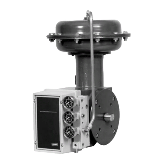
Figure 2. Type 1052 Actuator with J Mounting Adaptation
1051 & 1052 H & J
and Type 3610J Positioner
W4139-1 / IL
Advertisement
Table of Contents

Related Manuals for Emerson 1051


Summary of Contents for Emerson 1051
-
Page 1: Table Of Contents
Instruction Manual Form 5587 November 2006 Types 1051 and 1052 Sizes 40, 60 and 70 Styles H and J Rotary Actuators Contents Introduction ....... -
Page 2: November
1051 & 1052 H & J Operation Direct Acting: Increasing loading pressure extends the diaphragm rod out of the spring barrel Service: Type 1051: For on-off or throttling service with positioner Type 1052: For on-off or throttling service with or without a positioner Actuator Sizes... -
Page 3: Introduction
Scope of Manual This manual provides installation, adjustment, operation, maintenance, and parts ordering information for the Type 1051 (sizes 40 and 60) and Type 1052 (sizes 40, 60, and 70) diaphragm rotary actuators with H and J mounting adaptations (see figures 1 and 2). -
Page 4: Specifications
Specifications Specifications are shown in table 1 for Type 1051 and 1052 actuators. Specifications for a given Type 1051 or 1052 actuator as it originally comes from the factory are stamped on a nameplate attached to the actuator. Principle of Operation The diaphragm rod moves down as loading pressure is increased on top of the diaphragm. - Page 5 Then install the woodruff key (key 91) in the shaft keyseat, and slide the coupling onto the shaft. It is 1051 & 1052 H & J helpful to apply a light coat of grease to the inside of the coupling before sliding it onto the shaft.
- Page 6 WOODRUFF KEY 19A1465-C NOTE: SEE PARTS LIST FOR WOODRUFF KEY NUMBERS C0577-3 / IL Figure 4. Type 1051 Mounting Dimensions (refer to table 4) Table 4. Style H or J Mounting Dimensions Type 1051 Type 1052 – – – Inch 19.88...
- Page 7 19A1461-D 1/4-INCH NPT WOODRUFF KEY 19A1467-E / NOTE: SEE PARTS LIST FOR WOODRUFF KEY NUMBERS C0676-3 / IL Figure 5. Type 1052 Mounting Dimensions (refer to table 4) 19A1461-D 19A1461-G 1051 & 1052 H & J 1/4-INCH NPT S (DIA)
- Page 8 40, 60 & 38.1 1-1/2 1. Tolerance for the K dimension is indicated by showing maximum and minimum dimensions. Figure 6. Type 1051 and 1052 Style H Mounting Dimensions (refer to table 5) Table 5. Style H Mounting Dimensions Inch Inch 15.75...
- Page 9 2. The L dimension is the matchline to the end of the actuator shaft. 3. Size 70 is only available for the Type 1052. 19A1461-G Figure 7. Type 1051 and 1052 Style J Mounting Dimensions (refer to table 6) Table 6. Style J Mounting Dimensions Inch...
- Page 10 1051 & 1052 H & J TYPE 1051 SIZE SIZE – – – DESIRED DESIRED DESIRED DESIRED ACTUATOR ACTUATOR SHAFT ACTUATOR MOUNTING ROTATION, ACTION ACTION POSITION POSITION DEGREES Push Down to Push Down to 60 or 90 60 or 90...
-
Page 11: Loading Connections
Type 1051 actuator. Key numbers used in this procedure are shown in figure 12 for Type 1051 actuators and in figure 13 for Type 1052 actuators. For accurate adjustment, remove the valve body or other operated equipment from the pipeline. -
Page 12: Type 1052 Spring Adjustment
1051 & 1052 H & J Table 9. Wrench Sizes Required for Turnbuckle Adjustment, Inches TURN- ACTUATOR BUCKLE BUCKLE Type Size (KEY 57) 1051 & 1-1/8 1052 1-5/16 1052 1-5/16 3. Make sure the actuator housing (key 20) is clear of any tools or other instruments that could obstruct the actuator stroke path. -
Page 13: Stroking Range
Instructions are given below for disassembly and assembly of parts. Key numbers referenced in the following steps are shown in figure 12 for Type 1051 actuators and in figure 13 for Type 1052 actuators unless otherwise specified. -
Page 14: Disassembly
1051 & 1052 H & J Disassembly The following procedure describes how the actuator can be completely disassembled. When inspection or repairs are required, perform only those steps necessary to accomplish the procedure. Do not under ordinary circumstances remove the cap screws (keys 7, 8, and 21). - Page 15 12. Loosen, but do not remove, all casing cap screws (key 5). Make sure there is no spring force on the Type 1051 upper diaphragm casing. Unscrew and remove the cap screws and hex nuts (keys 5 and 6), and then remove the upper diaphragm casing and the diaphragm (key 3).
-
Page 16: Assembly
If the actuator is not completely disassembled, start these instructions at the appropriate step. Key numbers used are shown in figure 12 to Type 1051 actuators and in figure 13 for Type 1052 actuators. 1. If the Type 1052 spring barrel (key 12) was... - Page 17 3. If the bearing (key 67) was removed, press in the new bearing. The end of the bearing should be flush 1051 & 1052 H & J with the outside of the mounting bracket or mounting plate (key 22).
-
Page 18: Changing Actuator Mounting
1051 & 1052 H & J DESIRED ACTION OF Actuator Operated Equipment Push Down Clockwise to Close to Open to Open Counterclockwise to Close (PDTO) Push Down Clockwise to Close to Close to Close Counterclockwise to Close (PDTC) 1. This action uses the spring to close the valve body or other equipment. -
Page 19: Changing Positions
(key 78). Tighten the cap screws to the torque value listed in table 10. 1051 & 1052 H & J 7. Install the lever (key 27) as follows: a. For push-down-to-open action, rotate the operated equipment to the fully closed position. - Page 20 1051 & 1052 H & J 2. Mark the orientation of the lever (key 27) with respect to the output shaft (key 87). This marking is used during reassembly to allow for proper lever/output shaft positioning. When the lever and...
-
Page 21: Top-Mounted Handwheels And Adjustable Travel Stops
If repeated or daily manual operation is expected or desired, the unit should be equipped with a manual handwheel actuator. Refer to the separate manual 1051 & 1052 H & J handwheel actuator instruction manual for mounting instructions. The top-mounted handwheel assembly is attached... -
Page 22: Handwheel And Travel Stop Maintenance
1051 & 1052 H & J Handwheel and Travel Stop Maintenance WARNING Avoid personal injury or property damage from sudden release of process pressure or uncontrolled movement of parts. Before performing any maintenance operations: D Always wear protective gloves, clothing, and eyewear when performing any maintenance operations to avoid personal injury. -
Page 23: For Adjustable Down Travel Stops
4. Reassemble by reversing the order of the steps you took to disassemble, being sure to apply 1051 & 1052 H & J lubricant as previously mentioned and as shown by the lubrication boxes (key 241) in figures 15 and 16. -
Page 24: Parts List
1051 & 1052 H & J Parts List Retrofit Kits Kit provides parts to add a top-mounted handwheel. Kit number 1 includes the handwheel assembly only. Kit number 2 includes Kit number 1 and a new upper case (key 1) that is required to mount the handwheel assembly. - Page 25 Instruction Manual Form 5587 November 2006 D0299-1/IL Figure 12. Type 1051 Actuator with Typical H and J Mounting Adaptations Description Nut, hex Size 40 (16 req’d) Size 60 (24 req’d) Size 70 (28 req’d) Screw, cap, Hex hd Size 40 (4 req’d) Size 60 (6 req’d)
- Page 26 Instruction Manual Form 5587 1051 & 1052 H & J November 2006 59A2408-B D0299-2 Figure 12. Type 1051 Actuator with Typical H and J Mounting Adaptations (continued)
- Page 27 Instruction Manual Form 5587 November 2006 59A2420-A D0300–1/IL Figure 13. Type 1052 Actuator with Typical H and J Mounting Adaptations 1051 & 1052 H & J...
- Page 28 1051 & 1052 H & J 59A2420-A/DOC Figure 13. Type 1052 Actuator with Typical H and J Mounting Adaptations (continued) Description Lever Screw cap, Hex Hd Retaining Ring, Ext Bushing (2 req’d) Size 40 Sizes 60 & 70 Cover Screw, Cap, Hex Hd...
- Page 29 Nameplate Turnbuckle Nut, Hex, Jam Plate, Access Washer, Plain Type 1051 w/Type 304 or Type 4200 Size 40 (4 req’d) Sizes 60 & 70 (2 req’d) Ind, Travel (not shown)(w/Type 3555T) Screw, Mach, Fill hd (w/Type 3555T) Disc, Travel Indicator (w/Type 3555T) (not shown)
- Page 30 44.5 mm (1-3/4 inch) keyed equipment shaft (1 req’d) for 50.4 mm (2-inch) keyed equipment shaft (1 req’d) Keyed Equipment Shafts Part Number Description Diaphragm head, lower (Type 1051 w/adj down stop) Plug, protective polyethylene (Type 1052 Size 70) Actuator Output Shaft Retaining Ring Pin, Groove, Steel Alloy...
- Page 31 Plate, Pusher Nut, Travel Stop (Size 70) 138* O-Ring, Nitrile 1D237506992 1B885506992 1C415706992 1051 & 1052 H & J Size 40 Size 60 Size 70 Size 40 (6 req’d) Size 60 (8 req’d) Size 70 (12 req’d) (Type 1052 Size 70 only)
- Page 32 1051 & 1052 H & J Description 139* O-Ring, Nitrile Size 40 Size 60 Size 70 140* Groove Pin Size 40 Size 60 Cap Screw, Hex Hd, Steel Size 40 (6 req’d) Size 60 (8 req’d) Size 70 (12 req’d) Body Body Extension (Sizes 40 &...
- Page 33 3 to 15 3 to 15 0.2 to 2.1 3 to 30 1. For more detailed ordering information concerning proper spring selection to obtain the torque required by the valve, consult your Emerson Process Management sales office. INITIAL SPRING COMPRESSION Push-Down-to-Open SIZE...
- Page 34 3 to 30 3 to 30 1. For more detailed ordering information concerning proper spring and spring seat selection to obtain the torque required by the valve, contact your Emerson Process Management sales office. Key 91*. Woodruff Key for Actuator with J Mounting Adaptation, Alloy Steel...
- Page 35 Instruction Manual Form 5587 1051 & 1052 H & J November 2006 28A1207-B/DOC 28A1214-A/DOC CV8057-D/DOC Figure 16. Adjustable Up Travel Stops...
- Page 36 1051 & 1052 H & J Fishtail and Fisher are marks owned by Fisher Controls International LLC, a member of the Emerson Process Management business division of Emerson Electric Co. Emerson Process Management, Emerson, and the Emerson logo are trademarks and service marks of Emerson Electric Co.