Table of Contents
Advertisement
Quick Links
Instruction Manual
Form 5302
July 2006
Design CV500 Rotary Control Valve
Contents
. . . . . . . . . . . . . . . . . . . . . . . . . . . . . . .
. . . . . . . . . . . . . . . . . . . . . . . . .
. . . . . . . . . . . . . . . . . . . . . . . . . . . . . .
. . . . . . . . . . . . . . . . . . . . . . . . . . . .
. . . . . . . . . . . . . . . . . . . . . . . . . . . . . . . .
. . . . . . . . . . . . . . . . . . . . . . . . . . . . . .
. . . . . . . . . . . . . . . . . . . . . . . .
. . . . . . . . . . . . . . . . . . . . . . . . . . .
. . . . . . . . . . . . . . . . . . . . . . . . . . . . . .
. . . . . . . . . . . . . . . . . . . . . . . . . . .
. . . . . . . . . . . . . . . . . . . . . . . . . . . . . .
. . . . . . . . . . . . . . . . . . . . . . . . . . . .
. . . . . . . . . . . . . . . . . . . . . . . . . . . . . . . .
. . . . . . . . . . . . . . . . . . . . . . . . . . . . . . . .
Introduction
Scope of Manual
This instruction manual provides installation,
operation, maintenance, and parts ordering
information for 3- through 12-inch Design CV500
Cam Vee-Ballr rotary control valves. Refer to
separate manuals for information concerning the
actuator and accessories.
www.Fisher.com
. . . . . . . . . . . . . . . . . . . . .
. . . . . . . . . . . . . . . . . . . . . . .
. . . . . . . . . . . . . . . . . . . . . . .
. . . . . . . .
. . . . . . . . . . . . . . . . .
. . . . . . . . . . . .
. . . . . . . . .
1
1
2
2
3
7
8
8
8
9
11
12
14
14
16
W8192-1 / IL
19
19
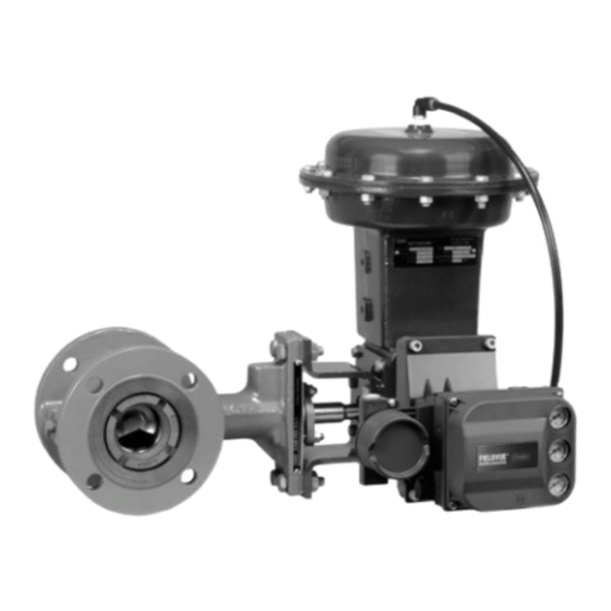
Figure 1. Design CV500 Flanged Valve with Type 1052
20
Actuator and Type DVC6020 Positioner
20
20
21
W5000-1 / IL
Figure 2. Design CV500 Wafer Valve with
CV500 Valve
Type 1066 Actuator
Advertisement
Table of Contents

Related Manuals for Emerson FISHER CV500


Summary of Contents for Emerson FISHER CV500
-
Page 1: Table Of Contents
Instruction Manual Form 5302 CV500 Valve July 2006 Design CV500 Rotary Control Valve Contents Introduction ....... Scope of Manual . -
Page 2: Description
J Right-hand or J left-hand as viewed from the (wafer) valve body sizes are available in certain upstream side of the valve ASME and PN ratings. Consult your Emerson Process Managementt sales office Mounting position depends on the desired open... -
Page 3: Installation
Instruction Manual Form 5302 CV500 Valve July 2006 Table 2. Maximum Allowable Shutoff Pressure Drops VALVE SIZE TEMPERATURE VALVE BODY BEARING MATERIAL MATERIAL −29 to 149 41.4 41.4 41.4 24.1 24.1 27.6 S44004 149 to 204 41.4 41.4 41.4 23.8 24.1 27.6 WCC steel... - Page 4 4. Before starting the actual installation of the valve, first contacting your Emerson Process determine the proper installation orientation of the Management sales office. V-notch ball (key 2) and actuator. Determine the flow Key numbers are shown in figure 11 for 3- direction of the process fluid through the valve.
- Page 5 Instruction Manual Form 5302 CV500 Valve July 2006 ACTUATOR POSITION ACTUATOR VALVE OPEN MOUNTING STYLE STYLE A (PDTC) RIGHT- HAND STYLE B (PDTO) STYLE C (PDTO) LEFT- HAND STYLE D (PDTC) NOTES: 1. ARROW ON LEVER INDICATES DIRECTION OF ACTUATOR THRUST TO CLOSE VALVE. 2.
- Page 6 Instruction Manual Form 5302 CV500 Valve July 2006 Line Studs (Key 36) Cap Screws (Key 37) Valve Valve Bolt Length, Bolt Overall Size Bolt Size Size Bolt Size Length, Length, PN 10-40 M16 x 2 PN 10-40 M16 x 2 PN63 M20 x 2.5 PN63...
-
Page 7: Maintenance
Instruction Manual Form 5302 CV500 Valve July 2006 Note graphited-composition packing ring with PTFE/composition packing) in For best shutoff performance, install order to electrically bond the shaft to the valve with the drive shaft the valve body. Alternate horizontal and the Vee-Ball closing in shaft-to-valve body bonding is the downward direction for standard available for hazardous service areas... -
Page 8: Packing Maintenance
Instruction Manual Form 5302 CV500 Valve July 2006 Valve parts are subject to normal wear and must be ACTUATOR VALVE BODY inspected and replaced as necessary. The frequency of inspection and replacement depends upon the severity of service conditions. Packing Maintenance Key numbers refer to figure 11 for 3- through 8-inch sizes and to figure 12 for 10- and 12-inch sizes unless otherwise indicated. -
Page 9: Replacing Retainer, Seat Ring, And Face Seals
Instruction Manual Form 5302 CV500 Valve July 2006 This procedure may be performed without removing CAUTION the actuator from the valve if adding PTFE/composition packing rings as a temporary measure. However, the actuator must be removed if In the following step, take care not to replacing any other kind of packing or if the metal scratch the valve shaft or packing box packing parts (keys 14, 17, and, if used, 18) need to... - Page 10 Instruction Manual Form 5302 CV500 Valve July 2006 LEAKOFF ARRANGEMENT DOUBLE PACKING ARRANGEMENT BRAIDED PTFE COMPOSITION & GRAPHITE RIBBON DOUBLE PACKING ARRANGEMENTS PRESSURE-VACUUM SERVICE PRESSURE SERVICE VACUUM SERVICE PTFE/V-RING DOUBLE PACKING ARRANGEMENTS FOR PURGED BEARING FOR PURGED BEARING CONSTRUCTION CONSTRUCTION GRAPHITE RIBBON OR PTFE V-RING PTFE-COMPOSITION PACKING...
-
Page 11: Disassembly
Instruction Manual Form 5302 CV500 Valve July 2006 C0774-1 / IL PTFE/COMPOSITION OR GRAPHITE ENVIRO-SEAL PACKING ARRANGEMENTS Figure 6. Packing Arrangements (Continued) A new retainer gasket (key 11) is required whenever CAUTION the retainer (key 5) is removed. Other parts that are in good condition can be reused. -
Page 12: Assembly
Instruction Manual Form 5302 CV500 Valve July 2006 Replacing Ball, Shaft, and Bearings procedure in this Table 4. Assembly Clearance manual. If the parts are in good condition and do not SEAT RING AND RETAINER CLEARANCE require replacement, continue to the Assembly PROCESS Inches TEMPERATURE... - Page 13 Instruction Manual Form 5302 CV500 Valve July 2006 VALVE SIZE (SQUARE) (SQUARE) Inches 79.2 33.3 41.4 19.0 3.12 1.31 1.62 104.6 33.3 41.4 25.4 4.12 1.31 1.62 1.00 155.4 38.1 11.2 63.5 11.2 25.4 6.12 1.50 2.50 1.00 203.2 50.8 11.2 101.6 11.2...
-
Page 14: Replacing Ball, Shaft, And Bearings
(key 16). If the packing is to personal injury. When the actuator is be reused, do not remove it. However, Emerson removed from the valve, the ball/shaft Process Management recommends that the packing assembly may suddenly rotate, be replaced whenever the drive shaft is removed. - Page 15 Instruction Manual Form 5302 CV500 Valve July 2006 Table 5. Data for Tapped Holes on Valve Shaft WARNING SHAFT DIAMETER THREAD Through Through VALVE To avoid personal injury or damage to Spline Spline SIZE, SIZE Valve Valve tools, valve parts, or other items Inches resulting from the ball (key 2) falling from the valve body, support the ball...
-
Page 16: Assembly
Instruction Manual Form 5302 CV500 Valve July 2006 MAX. VALVE MIN. SIZE Inches Inches 27.8 1.094 6.50 27.4 1.078 34.1 1.344 6.50 33.7 1.328 DRIVE PINS OUT FROM THIS END 42.1 1.656 7.75 (SMALLER HOLE) 41.7 1.641 42.1 1.656 9.00 41.7 1.641 48.4... - Page 17 Instruction Manual Form 5302 CV500 Valve July 2006 box in step 4. Stop before the drive shaft enters the PINS GO IN FROM THIS END (LARGER HOLE) main valve body cavity. Support the splined end of the shaft. For 10- and 12-inch sizes, inspect the drive shaft (key 3).
- Page 18 Instruction Manual Form 5302 CV500 Valve July 2006 Note application of excessive force on the expansion pin, use appropriate care When the valve drive shaft is correctly when driving the expansion pin positioned for 3- through 8-inch sizes, through the ball and drive shaft. Use the slash mark on the splined end will the correct tool.
-
Page 19: Adjusting Actuator Travel
Instruction Manual Form 5302 CV500 Valve July 2006 Adjusting Actuator Travel select actuator mounting style and position and to orient the actuator lever with the valve drive shaft Perform this procedure whenever the actuator is (key 3). removed or disconnected from the valve and whenever the seat ring and retainer (keys 4 and 5) 2. -
Page 20: Changing Actuator Mounting Style
O-ring (sealed bearing only) stamped on the nameplate. Always refer to this serial number when corresponding with your Emerson Process Management sales office regarding spare parts or technical information. When Retrofit Kits for ENVIRO-SEAL Packing ordering replacement parts, also specify the... -
Page 21: Parts List
12A8832X012 Keys 1 and 7 are included in the valve body/bearing 4-inch 12A8951X012 assembly. If a part number is required, contact 6- & 8-inch 12A8935X012 your Emerson Process Management sales office for 10-inch 12A9057X012 assistance 12-inch 1R516201012 Ball Braided PTFE/composition and Graphite Rings (see figure 6) - Page 22 Instruction Manual Form 5302 CV500 Valve July 2006 Description Part Number Description Part Number Packing Box Ring Packing Set, (cont’d) Use w/all packing box constructions Graphite Ribbon Rings (see figure 6) 316 SST For single packing arrangements, order 3-inch 16A6085X012 4 graphite ribbon rings (key 13), and 3 4-inch 16A6086X012...
- Page 23 Instruction Manual Form 5302 CV500 Valve July 2006 TCM SEAL DOUBLE PACKING SEALED BEARING APPLY LUB KEY NUMBERS NOT SHOWN ARE 28, 30, 31, 33, 36, 37, 130, AND 131 NOTE: MEASURE GAP HERE 42B3374-A / IL Figure 11. 3- Through 8-Inch Design CV500 Valve...
- Page 24 Instruction Manual Form 5302 CV500 Valve July 2006 DOUBLE PACKING SEALED BEARING APPLY LUB KEY NUMBERS NOT SHOWN ARE 28, 30, 31, 33, 36, 37, 130, AND 131 NOTE: MEASURE GAP HERE 42B5286-A / IL Figure 12. 10- and 12-Inch Design CV500 Valve...
- Page 25 Instruction Manual Form 5302 CV500 Valve July 2006 Description Part Number Description Part Number O-Ring (for sealed bearings, 2 req’d) 106* Anti-Extrusion Ring, Composition/graphite Nitrile filled PEEK (2 req’d) 3-inch 10A8217X042 Single PTFE packing w/std packing box 4-inch 10A3803X012 1-inch 12B7054X012 6- &...
- Page 26 Instruction Manual Form 5302 CV500 Valve July 2006 42B8445-B SINGLE PTFE PACKING STANDARD DEPTH BOX 14B0095-A STACKING ORDER OF PTFE PACKING RINGS 42B8445-B 42B8445-B DOUBLE PTFE PACKING DOUBLE PTFE PACKING WITH LEAKOFF STANDARD DEPTH PACKING BOX NOTES: OPTIONAL DEEP PACKING BOX APPLY LUBRICANT.
- Page 27 Instruction Manual Form 5302 CV500 Valve July 2006 Key 4* Seat Ring—Full Port, Use w/Metal Seal Construction MATERIAL VALVE SIZE, CF8M CF3M R30006 CF8M CF3M INCHES (316 SST) (316L SST) (Alloy 6) w/CoCr-A Seat w/CoCr-A Seat 29A3703X012 29A3703X092 29A3703X022 - - - - - - 29A3667X012 29A3667X102...
- Page 28 Process Management business division of Emerson Electric Co. Emerson Process Management, Emerson, and the Emerson logo are trademarks and service marks of Emerson Electric Co. All other marks are the property of their respective owners. This product may be covered under one or more of the following patents: 4,516,579;...