Emerson Fisher 1052 Instruction Manual
Rotary actuator with h mounting adaptation
Hide thumbs
Also See for Fisher 1052:
- Instruction manual (12 pages) ,
- Safety manual (9 pages) ,
- Instruction manual (28 pages)
Table of Contents
Advertisement
Quick Links
Instruction Manual
D100323X012
Fisher
1052 Size 20 Diaphragm Rotary Actuator
™
with H Mounting Adaptation
Contents
. . . . . . . . . . . . . . . . . . . . . . . . . . . . . . . . .
. . . . . . . . . . . . . . . . . . . . . . . . . . . . .
. . . . . . . . . . . . . . . . . . . . . . . . . . . . . . . . .
. . . . . . . . . . . . . . . . . . . . . . . . . . . . . . .
. . . . . . . . . . . . . . . . . . . . . . . . . . . . . . . . . .
. . . . . . . . . . . . . . . . . . . . . . . . . .
. . . . . . . . . . . . . . . . . . . . . . . . . . . . . . . . .
. . . . . . . . . . . . . . . . . . . . . . . . . . . . . . . .
. . . . . . . . . . . . . . . . . . . . . . . . . . . . . . . . . . .
. . . . . . . . . . . . . . . . . . . . . . . . . . . . .
. . . . . . . . . . . . . . . . . . . . . . . . .
. . . . . . . . . . . . . . . . . . . . . . . . . . . . . . .
. . . . . . . . . . . . . . . . . . . . . . . . . . . . . . . . . .
. . . . . . . . . . . . . . . . . . . . . . . . . . . . . . .
. . . . . . . . . . . . . . . . . . . . . . . . . . . . . . . . . . .
Introduction
Scope of Manual
This instruction manual includes installation, adjustment, operation, maintenance, and parts ordering information for
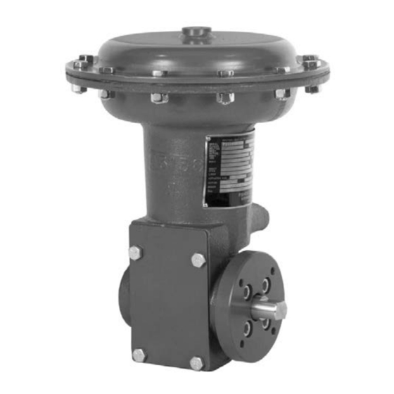
the Fisher 1052 size 20 diaphragm rotary actuator with H mounting (figure 1) and the optional top-mounted
handwheel (see figure 7). Instructions for the rotary positioner and other accessories are included in separate
instruction manuals.
Do not install, operate, or maintain a 1052 actuator without being fully trained and qualified in valve, actuator, and
accessory installation, operation, and maintenance. To avoid personal injury or property damage, it is important to
carefully read, understand, and follow all the contents of this manual, including all safety cautions and warnings. If you
have any questions about these instructions, contact your
proceeding.
www.Fisher.com
. . . . . . . . . . . . . . .
. . . . . . . . . . . . . . . . .
. . . . . . . . . . . . . . . . . . . . . . . . .
. . . . . . . . . . . . . . . . . . . . . . . .
. . . . . . . . . . . . . . . . . .
. . . . . . . . . . . . . . . . . . . . .
Figure 1. Fisher 1052 Size 20 Actuator
with H Mounting Adaptation
1
1
2
2
3
3
3
4
4
5
6
6
8
9
9
11
11
12
12
12
13
W4140-1
Emerson sales office
1052 Size 20 Actuator (H)
or Local Business Partner before
June 2017
Advertisement
Table of Contents

Related Manuals for Emerson Fisher 1052


Summary of Contents for Emerson Fisher 1052
-
Page 1: Table Of Contents
This instruction manual includes installation, adjustment, operation, maintenance, and parts ordering information for the Fisher 1052 size 20 diaphragm rotary actuator with H mounting (figure 1) and the optional top‐mounted handwheel (see figure 7). Instructions for the rotary positioner and other accessories are included in separate instruction manuals. -
Page 2: Description
Direct‐Increasing loading pressure forces the spring compression, and supply pressure. If stroking diaphragm rod from the top to the bottom of the time is critical, consult your Emerson sales office casing Local Business Partner. Casing Pressure Ranges Material Temperature Capabilities 0 to 1.2 bar (10 to 18 psig), J 0 to 2.3 bar (0 to... -
Page 3: Installation
Instruction Manual 1052 Size 20 Actuator (H) D100323X012 June 2017 Installation WARNING Always wear protective gloves, clothing, and eyewear when performing any maintenance operations to avoid personal injury. Personal injury or equipment damage caused by sudden release of pressure might result if the valve assembly is installed where service conditions could exceed the limits given in table 1 or on the appropriate nameplates. -
Page 4: Stroking Range
Instruction Manual 1052 Size 20 Actuator (H) June 2017 D100323X012 Figure 2. Spring Adjustment NOTCHED PORTION OF SPRING ADJUSTER DOWN TRAVEL STOP TRAVEL INDICATOR TRAVEL STOP CLAMPED W6761‐1 LEVER Proper bench set of the spring can only be made when the actuator “up” travel stop has been approximately adjusted. Insert a shaft in the actuator and adjust the “up”... -
Page 5: Principle Of Operation
Instruction Manual 1052 Size 20 Actuator (H) D100323X012 June 2017 Figure 3. Center of Gravity Dimensions (4.91) (INCH) 58.7 (2.31) NOTE: CENTER OF GRAVITY INCLUDES YOKE WEIGHT. 14B8083-A Note Find dimensions and center of gravity information in figures 3 and 4 and the approximate weight in table 1. This information is required for fabrication of the proper bracket and coupling. -
Page 6: Maintenance
Instruction Manual 1052 Size 20 Actuator (H) June 2017 D100323X012 The spring and diaphragm are selected to meet the requirements of the application and, in service, the actuator should produce full travel of the operated equipment with the diaphragm pressure as indicated on the nameplate. Consult the positioner instruction manual for actuator principle of operation with positioner. - Page 7 Instruction Manual 1052 Size 20 Actuator (H) D100323X012 June 2017 (ACTUATOR OUTPUT SHAFT DIAMETER) 15.75 57.2 19.1 22.2 57.2 28.4 26.2 5/16‐18 UNC 63.5 15.62 Inches 0.620 10.06 2.25 7.25 6.75 0.75 2.25 1.12 1.03 5/16‐18 UNC 2.50 0.615 1. Tolerance for K dimension is indicated by showing maximum and minimum dimensions. Figure 4.
-
Page 8: Assembly
Instruction Manual 1052 Size 20 Actuator (H) June 2017 D100323X012 assembly (key 10) from the lever (key 27). Remove the lever with the attached travel stops and hex nuts (keys 8 and 86). 10. Pull the diaphragm plate (key 4) and attached diaphragm rod (key 10) out of the actuator. Remove the cap screw (key 9) and washer (key 79) and separate the diaphragm plate and diaphragm rod. -
Page 9: Changing Actuator Mounting
Instruction Manual 1052 Size 20 Actuator (H) D100323X012 June 2017 10. Attach the output shaft (key 87) to the mounting plate (key 22) with the retaining ring (key 88). Then, with the actuator at the top of its stroke, attach the mounting plate and output shaft assembly to the actuator housing (key 20) with the cap screws (key 23) so that the markings that were made in step 5 of the Disassembly procedure are oriented correctly (output shaft to actuator housing and travel indicator to travel indicator scale). - Page 10 Instruction Manual 1052 Size 20 Actuator (H) June 2017 D100323X012 5. Rotate the actuator housing 180 degrees while maintaining the appropriate position (1, 2, 3, or 4). DESIRED ACTION OF HOUSING CONSTRUCTION TO SPECIFY Actuator Valve Body or Other Equipment Clockwise to Close Style A Push Down To Open...
-
Page 11: Changing Positions
Instruction Manual 1052 Size 20 Actuator (H) D100323X012 June 2017 with the self‐tapping screws or cap screws (key 36). When attaching the travel indicator scale, make certain that it is properly aligned with the travel indicator. 11. Replace the cover and machine screws (keys 40 and 39). Changing Positions 1. -
Page 12: Disassembly
WARNING Use only genuine Fisher replacement parts. Components that are not supplied by Emerson Automation Solutions should not, under any circumstances, be used in any Fisher valve, because they may void your warranty, might adversely affect the... -
Page 13: Parts List
W/o switches W/switches 38 Cap Screw, pl carbon steel (2 req'd) Note (for use w/GO switch only) Contact your Emerson sales office or Local Business Partner for Part 38 Cap Screw (2 req'd) Ordering information. (for use w/ 304 Switch) 39 Cover Plate, steel (used w/o positioner) 40... - Page 14 Instruction Manual 1052 Size 20 Actuator (H) June 2017 D100323X012 Figure 6. Actuator Assembly with H Mounting Adaptation NOTES: [76] APPLY LITHIUM GREASE. 49A2404‐C...
- Page 15 Instruction Manual 1052 Size 20 Actuator (H) D100323X012 June 2017 Figure 6. Actuator Assembly with H Mounting Adaptation (continued) NOTES: [76] APPLY LITHIUM GREASE. [77] APPLY THREAD LOCKING ADHESIVE (MEDIUM STRENGTH) 49A2404‐C...
- Page 16 Responsibility for proper selection, use, and maintenance of any product remains solely with the purchaser and end user. Fisher and GO are marks owned by one of the companies in the Emerson Automation Solutions business unit of Emerson Electric Co. Emerson Automation Solutions, Emerson, and the Emerson logo are trademarks and service marks of Emerson Electric Co.