Table of Contents
Advertisement
Quick Links
Instruction Manual
Form 5062
May 2008
Type 1051 and 1052 Style F and G
Size 40, 60, and 70 Rotary Actuators
Contents
. . . . . . . . . . . . . . . . . . . . . . . . . . . . . . .
. . . . . . . . . . . . . . . . . . . . . . . . .
. . . . . . . . . . . . . . . . . . . . . . . . . . . . . .
. . . . . . . . . . . . . . . . . . . . . . . . . . . .
. . . . . . . . . . . . . . . . . . . . . . . . . . . . . . . .
. . . . . . . . . . . . . . . . . . . . . . . .
. . . . . . . . . . . . . . . . . . . . . . . . . . . .
. . . . . . . . . . . . . . . . . . . . . . . . .
. . . . . . . . . . . . . . . . . . . . . . . . . . . . . .
. . . . . . . . . . . . . . . . . . . . . . . . . . . . .
. . . . . . . . . . . . . . . . . . . . . . . . . . . . . . .
. . . . . . . . . . . . . . . . . . . . . . . . . . .
. . . . . . . . . . . . . . . . . . . . . . .
. . . . . . . . . . . . . . . . . . . . . . . . . .
. . . . . . . . . . . . . . . . . . . . . . . . . . . .
. . . . . . . . . . . . . . . . . . . . . . . . . .
Introduction
Scope of Manual
This instruction manual includes installation,
adjustment, maintenance, and parts ordering
information for the Type 1051 (size 40 and 60) and
Type 1052 (Size 40, 60, and 70) pneumatic piston
rotary actuator with F and G mounting adaptations
(see figure 1).
The G mounting adaptation is for Type 7600 and
9500 valves, and the F mounting adaptation is for all
www.Fisher.com
. . . . . . . . . . . . . . . . . . . . . .
. . . . . . . . . . . . . . . . . . . . . . .
. . . . . . . . . . . . . . . . . . . .
. . . . . . . . . . . . . .
. . . . . . . . . . . . . . . . . . . . .
. . . . . . . . . . . . . .
. . . . . . . . . . . . . . . . .
. . . . . .
. . . . . . . . . .
. . . . . . . . .
1051 & 1052 F & G Actuators
1
1
3
3
3
4
6
7
7
8
8
8
9
9
9
11
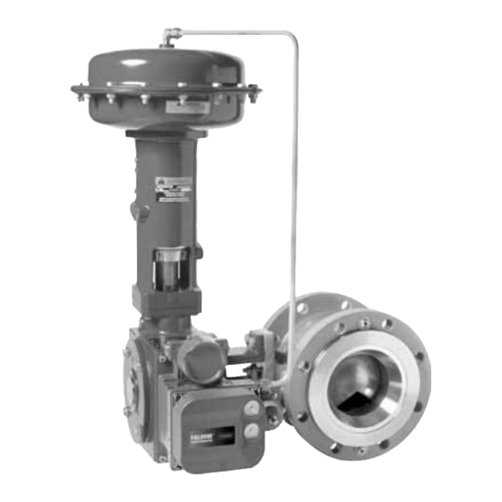
W8508-2
13
Figure 1. Vee-Ballr Valve with Type 1052 Actuator and
Type DVC6020 Digital Valve Controller
14
14
other eccentric disc or Vee-Ballr valves. Also, this
instruction manual provides information for the
15
optional top-mounted handwheel, up and down
17
travel stops, locking mechanism, and pipe-away
17
vent.
18
20
Instructions for the control valve, positioner,
21
accessories, and other sizes of actuators are
21
covered in separate instruction manuals.
Top-Mounted handwheels can be applied for
infrequent service as a manual handwheel actuator.
Also, an adjustable up travel stop can be added to
the actuator to limit its stroke in the upward direction,
or an adjustable down travel stop can be added to
limit actuator stroke in the downward direction.
Do not install, operate, or maintain a Type 1051 or
1052 actuator without first D being fully trained and
qualified in valve, actuator, and accessory
installation, operation, and maintenance, and D
carefully reading and understanding the contents of
this manual. If you have any questions about these
instructions, contact your Emerson Process
Managementt sales office before proceeding.
Advertisement
Table of Contents

Related Manuals for Emerson Fisher 1051


Summary of Contents for Emerson Fisher 1051
-
Page 1: Table Of Contents
(see figure 1). this manual. If you have any questions about these The G mounting adaptation is for Type 7600 and instructions, contact your Emerson Process 9500 valves, and the F mounting adaptation is for all Managementt sales office before proceeding. - Page 2 Dependent on actuator size, rotation, spring rate, initial spring compression, and supply pressure. If positioner Type 1052: For on-off or throttling service with or stroking time is critical, consult your Emerson Process Management sales office without a positioner Material Temperature Capabilities Actuator Sizes NBR (Nitrile) Diaphragm: –40 to 82_C (–40 to...
-
Page 3: Description
Note valve. Follow the valve body instructions when installing the control valve in the pipeline, and then Neither Emerson, Emerson Process perform the procedures presented in the Loading Management, nor any of their affiliated Connection section. If the actuator is shipped... -
Page 4: Actuator Mounting
Instruction Manual Form 5062 1051 & 1052 F & G Actuators May 2008 Table 3. Recommended Bolting Torques ACTUATOR SIZE DESCRIPTION KEY DESCRIPTION, KEY NUMBER NUMBER Size Size Size lbfSft lbfSft lbfSft Diaphragm Casing, 5 3/8-24 3/8-24 3/8-24 Casing to spring barrel, 7 3/8-16 3/8-16 1/2-13... - Page 5 Instruction Manual Form 5062 1051 & 1052 F & G Actuators May 2008 VALVE SERIES OR DESIGN VALVE SERIES OR DESIGN BALL/PLUG DISC/BALL 8510B, 8532, MOUNTING MOUNTING ACTION ACTION CV500 CV500 ROTATION TO ROTATION TO V250 V250 V150 V200 & V300 V150, V200 &...
-
Page 6: Valve Flow Direction
Instruction Manual Form 5062 1051 & 1052 F & G Actuators May 2008 1-1/2 inch shafts is 136 NSm (100 lbfSft); for 1-3/4 to the valve position just noted. Replace the cover 2-inch shafts is 183 NSm (135 lbfSft). (key 33), and secure with washers and cap screws (keys 34 and 63). -
Page 7: Loading Connection
Instruction Manual Form 5062 1051 & 1052 F & G Actuators May 2008 Table 4. Wrench Size Required for Turnbuckle 34.9 (1.375) Adjustment, Inches TURN- LOWER UPPER ACTUATOR OPERATING CLEARANCE (0.0625) BUCKLE BUCKLE LOCKNUT LOCKNUT LOCKNUT LOCKNUT Type Size (KEY 57) (KEY 16) (KEY 58) 1051 &... -
Page 8: Type 1052 Spring Adjustment
Instruction Manual Form 5062 1051 & 1052 F & G Actuators May 2008 a. Push-down-to-close—Slowly stroke the 33, 0 to 40, or 0 to 55 psig) depending on specific actuator to the down travel stop. Adjust the actuator size and construction. turnbuckle (key 57) until the valve is in the closed If the actuator has been disassembled or if the position. -
Page 9: Principle Of Operation
Instruction Manual Form 5062 1051 & 1052 F & G Actuators May 2008 D Use lock-out procedures to be Principle of Operation sure that the above measures stay in The diaphragm rod moves down as loading pressure effect while you work on the is increased on top of the diaphragm. - Page 10 Instruction Manual Form 5062 1051 & 1052 F & G Actuators May 2008 D Loosen, but do not remove, all casing cap 5. Remove the retaining ring (key 30), and slide the hub (key 29) from the cover. If necessary, remove screws and hex nuts (keys 5 and 6).
-
Page 11: Assembly
Instruction Manual Form 5062 1051 & 1052 F & G Actuators May 2008 before completely removing the cap screw (key 9) Assembly could cause personal injury due to the sudden This procedure assumes that the actuator was release of spring compression. completely disassembled. - Page 12 Instruction Manual Form 5062 1051 & 1052 F & G Actuators May 2008 actuator and lead to possible personal thread-locking compound as shown in figure 9, and injury or property damage. install the entire assembly into the spring barrel (key 12). Let the adjusting screw stand undisturbed 5.
-
Page 13: Changing Actuator Mounting
Instruction Manual Form 5062 1051 & 1052 F & G Actuators May 2008 SIZE 40 SIZE 60 AND 70 A2534-1 / IL Figure 5. Travel Stop Orientation 13. Refer to the appropriate valve instruction CAUTION manual for lever/valve shaft orientation marks, and slide the lever (key 27) into place;... -
Page 14: Top-Mounted Handwheels And Adjustable Travel Stops
Instruction Manual Form 5062 1051 & 1052 F & G Actuators May 2008 styles A and D to styles B and C or vice versa or to 6. Secure actuator housing (key 20) to the mounting change the mounting position. yoke (key 22) with cap screws (key 23). -
Page 15: Handwheel Maintenance And Adjustable Travel Stop
Instruction Manual Form 5062 1051 & 1052 F & G Actuators May 2008 be equipped with a manual handwheel to allow more travel. Lock the jam nut against the actuator. Refer to the separate manual hex nut, and replace the closing cap after the handwheel actuator instruction manual adjustment has been made. - Page 16 Instruction Manual Form 5062 1051 & 1052 F & G Actuators May 2008 2. Relieve all actuator spring compression by For size 70: The pusher unit is held to the following the procedures presented in the stem by a retaining screw (key 174, figures 10, 11 Disassembly portion of the Maintenance section.
-
Page 17: Locking Mechanism
In the larger sized actuators, the layers 1. To add the locking mechanism to an existing of the mounting plate assembly may actuator, contact your Emerson Process be far enough apart that you will need Management sales office to purchase the required parts. -
Page 18: Operating The Locking Mechanism
Instruction Manual Form 5062 1051 & 1052 F & G Actuators May 2008 Operating the Locking Mechanism To Lock the Actuator 1. Make sure the actuator diaphragm rod is To Unlock the Actuator retracted fully. This will be the locked position of the 1. - Page 19 Instruction Manual Form 5062 1051 & 1052 F & G Actuators May 2008 32A9325-F / IL 34B4646-B / IL NOTE: NOTE: FOR FIELD CONVERSION OF TYPE 1052 ACTUATORS, IF ACCESSORIES ARE NOT INSTALLED ON THE ATTACH COVER (KEY 141) OVER THE SPRING BARREL MOUNTING BOSS, INSTALL CAP SCREWS (KEY 143) TO ADJUSTMENT OPENING WITH SELF-TAPPING SCREWS PLUG OPENINGS.
-
Page 20: Pipe-Away Vent
Instruction Manual Form 5062 1051 & 1052 F & G Actuators May 2008 Pipe-Away Vent Bushings—Remove the mounting yoke bushing (key 67), and the end plate cover bushing (key 31, figures 8 and 9). Replace them with the pipe-away WARNING vent parts, as shown in figure 7. -
Page 21: Parts Ordering
Instruction Manual Form 5062 1051 & 1052 F & G Actuators May 2008 Parts Ordering Kit Number 1 When corresponding with your Emerson Process Description Part Number Management sales office about this equipment, refer Size 40 38A1213X032 to the serial number found on the actuator... - Page 22 Size 60 2E859802202 Part numbers shown are for recommended spares Size 70 2N130902202 only. For part numbers not shown, contact your VMQ/polyester Emerson Process Management sales office. Standard w/handwheel, or w/adj up stop Description Part Number Size 40 2E6700X0012 Size 60...
- Page 23 Instruction Manual Form 5062 1051 & 1052 F & G Actuators May 2008 j APPLY LUBRICANT/SEALANT 55A9255-B / IL B2679 / IL Figure 8. Typical Type 1051 Actuator Assembly (Continued) Description Part Number Description Part Number Screw, Cap, Hex Hd, Nut, Hex Size 40 (12 req’d) Bearing Rod End...
- Page 24 Instruction Manual Form 5062 1051 & 1052 F & G Actuators May 2008 Description Part Number Description Part Number Screw, Cap, Hex Hd w/o switches, w/Type 304, Type 4200, 140* Pin, Groove w/BZE6-2RN or DTE6-2RN SW, Carbon Steel-Plated w/micro switch w/90 deg, or w/ Type 3710 positioner Size 40 1F118028992 (4 req’d)
- Page 25 Instruction Manual Form 5062 1051 & 1052 F & G Actuators May 2008 j APPLY LUBRICANT/SEALANT 58A9224-A B2680 / IL Figure 9. Typical Type 1052 Assembly...
- Page 26 Instruction Manual Form 5062 1051 & 1052 F & G Actuators May 2008 55A9224-A / IL SECTION A A FOR SIZE 40, 60, AND 70 ACTUATORS Figure 9. Typical Type 1052 Assembly (continued)
- Page 27 Instruction Manual Form 5062 1051 & 1052 F & G Actuators May 2008 j APPLY LUBRICANT j APPLY LUBRICANT/SEALANT 38A1213-B / IL CV8010-G / IL TOP MOUNTED HANDWHEEL ASSEMBLY FOR TOP MOUNTED HANDWHEEL ASSEMBLY FOR SIZE 40 AND 60 ACTUATORS SIZE 70 ACTUATOR Figure 10.
- Page 28 Instruction Manual Form 5062 1051 & 1052 F & G Actuators May 2008 j APPLY LUBRICANT 28A1214-A / IL ADJUSTABLE UP TRAVEL STOP FOR j APPLY LUBRICANT SIZE 60 ACTUATORS 28A1207-B / IL ADJUSTABLE UP TRAVEL STOP FOR SIZE 40 ACTUATORS j APPLY LUBRICANT/SEALANT CV8057-E / IL ADJUSTABLE UP TRAVEL STOP FOR SIZE 70...
- Page 29 Instruction Manual Form 5062 1051 & 1052 F & G Actuators May 2008 Cap Screw Pipe-Away Vent (Figure 7) Description Part Number Complete retrofit kits are listed at the beginning of the parts list. Use this listing for individual replacement parts 132* Lined Bushing (steel/PTFE) yoke side 12.7 mm (1/2 inch) dia.
- Page 30 1K162827082 12A9449X012 1N937327082 12A9449X012 1. For more detailed ordering information concerning spring selection to obtain the torque required by the valve, consult your Emerson Process Management sales office. Key 11. Spring for Type 1052 Actuators Only (Steel) INITIAL SPRING COMPRESSION...
- Page 31 Instruction Manual Form 5062 1051 & 1052 F & G Actuators May 2008 Keys 22 and 67 . Mounting Yoke Assembly VALVE SHAFT VALVE SHAFT ACTUATOR KEY 22 YOKE KEY 67 DIAMETER DIAMETER VALVE DESIGN VALVE DESIGN SIZE SIZE CAST IRON CAST IRON BUSHING PTFE BUSHING, PTFE...
- Page 32 May 2008 Vee-Ball and Fisher are marks owned by Fisher Controls International LLC, a member of the Emerson Process Management business division of Emerson Electric Co. Emerson Process Management, Emerson, and the Emerson logo are trademarks and service marks of Emerson Electric Co.