Table of Contents
Advertisement
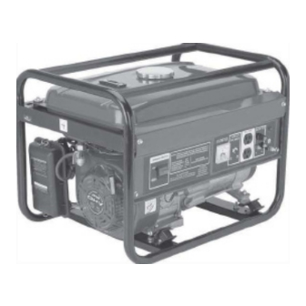
2200 RATED WATTS/2400 MAX WATTS
PORTABLE GENERATOR
Visit our website at: http://www.harborfreight.com
Read this material before using this product.
Failure to do so can result in serious injury.
SAVE ThiS MANuAL.
Copyright
2009 by Harbor Freight Tools
©
contained herein may be reproduced in any shape or form without the express written consent of
Harbor Freight Tools. Diagrams within this manual may not be drawn proportionally. Due to continuing
improvements, actual product may differ slightly from the product described herein. Tools required for
assembly and service may not be included.
For technical questions or replacement parts, please call 1-800-444-3353.
Revised Manual 10e
OPERATiNG iNSTRucTiONS
. All rights reserved. No portion of this manual or any artwork
®
98452
Advertisement
Table of Contents

Related Manuals for Chicago Electric 98452


Summary of Contents for Chicago Electric 98452
-
Page 1: Operating Instructions
2200 RATED WATTS/2400 MAX WATTS PORTABLE GENERATOR 98452 OPERATiNG iNSTRucTiONS Visit our website at: http://www.harborfreight.com Read this material before using this product. Failure to do so can result in serious injury. SAVE ThiS MANuAL. Copyright 2009 by Harbor Freight Tools . -
Page 2: Specifications
SPEciFicATiONS VAC Electrical Specifications 115 Volts @ 20 Amps Current Output 60 Hz 2200 Rated Watts / 2400 Max Watts Two 120V, Household Receptacles with a 20 Amp circuit breaker VDC Electrical Specifications 12 VDC @ 10 Amps Current Output Voltmeter Equipped 0-150 Volts / 50 Volt Increments Display Lights... -
Page 3: General Safety Rules
uNPAcKiNG When unpacking, check to make sure all the parts shown on the Parts LIsts on pages 20 and 22 are included. If any parts are missing or broken, please call Harbor Freight Tools at the number shown on the cover of the manual as soon as possible. GENERAL SAFETY RuLES WARNiNG! READ AND uNDERSTAND ALL iNSTRucTiONS... -
Page 4: Personal Safety
Do not expose power tools to rain or wet conditions. Water entering a generator will increase the risk of electric shock. Do not abuse the Power cords. Never use a Power cord to carry tools or pull the Plug from the outlet. Keep Power cords away from heat, oil, sharp edges, or moving parts. - Page 5 the generator. Such preventive safety measures reduce the risk of starting the generator accidentally. Store idle generators out of reach of children and other untrained persons. Generators are dangerous in the hands of untrained users. Maintain generators with care. Do not use a damaged generator. Tag damaged generators “Do not use”...
- Page 6 Maintain labels and nameplates on the Generator and Engine. These carry important information. If unreadable, or missing, contact Harbor Freight Tools for a replacement. Generator service must be performed only by qualified repair personnel. Service or maintenance performed by unqualified personnel could result in a risk of injury.
-
Page 7: Installation Precautions
SPEciFic SAFETY RuLES AND PREcAuTiONS hEART PAcEMAKER PREcAuTiON WARNiNG! People with pacemakers should consult their physician(s) before using this product. Electromagnetic fields in close proximity to a heart pacemaker could cause interference to or failure of the pacemaker. iNSTALLATiON PREcAuTiONS Ensure installation meets all applicable safety, and local and national electrical codes. -
Page 8: Fire And Explosion Precautions
Install sound and weather proofing only when it is not raining or snowing to avoid trapping moisture with the Generator’s area. FiRE AND EXPLOSiON PREcAuTiONS Gasoline fuel and fumes are flammable, and potentially explosive. proper fuel storage and handling procedures. Always have multiple ABC class fire extinguishers nearby. -
Page 9: Mechanical Precautions
MEchANicAL PREcAuTiONS ALWAYS make sure the Power Switch is in its “OFF” position. Disconnect the spark plug wire, and allow the Engine to completely cool before carrying our maintenance. check for damaged parts. Before using the Generator, any part that appears damaged should be carefully checked to determine that it will operate properly and perform its intended function. -
Page 10: Electrical Precautions
NOiSE PREcAuTiON Prolonged exposure to noise levels above 85 dBA is hazardous to hearing. Always wear ANSI approved ear protection when operating or working around the Generator when it is running. ELEcTRicAL PREcAuTiONS All connections and conduits from the Generator to the load must only be installed by trained and licensed electricians, and in compliance with all relevant local, state, and federal electrical codes and standards, and other regulations where applicable. - Page 11 Keep all electrical equipment clean and dry. Replace any wiring where the in- sulation is cracked, cut, abraded, or otherwise degraded. Replace terminals that are worn, discolored, or corroded. Keep terminals clean and tight. insulate all connections and disconnected wires. Guard against electric shock.
-
Page 12: Grounding The Generator
GENERATOR SuPPORT AND MOuNTiNG Mount the Generator on a concrete slab capable of supporting the weight of the Gen- erator. The slab must extend on all sides beyond the Frame (41B) by a least one foot. Contact a cement contractor for slab specifications if necessary. Attach the Frame to the concrete slab using 3/8”... - Page 13 Ac Applications Before connecting an appliance or power cord to the generator: Make sure that it is in good working order. Faulty appliances or power cords can create a potential for electrical shock. If an appliance begins to operate abnormally, becomes sluggish or stops suddenly, turn it off immediately.
- Page 14 ThiS GENERATOR hAS AN AuTO- ShuTDOWN OiL SENSOR. iF ENGiNE STOPS OR WiLL NOT START, chEcK OiL LEVEL. REV 09h SKU 98452 For technical questions, please call 1-800-444-3353. Page 14...
- Page 15 Before the first use, remove the Fuel Tank Cap (33B ) and fill the Fuel Tank (30B with unleaded gasoline. Then, replace the Fuel Tank Cap. If necessary, refill the Fuel Tank with unleaded gasoline. (See Figure c.) To Start The Engine: Make sure the electrical powered tools/equipment that will be used is not plugged in to the Generator.
- Page 16 Turn the Engine Power Switch (2) to its “ON” position. (See Figure F.) Hold the Start Handle (41A) loosely and pull it slowing several times to allow the gasoline to flow into the Engine’s carburetor. Then hold the Start Handle firmly and pull the rope hard and fast.
- Page 17 Powering 120 Volt AC Tools and Equipment: Prior to powering tools and equipment, make sure the Generator’s rated voltage, and amperage capacity (115 VAc / 20 AMPs) is adequate to supply all electrical loads that the unit will power. If powering exceeds the Generator’s capacity, it may be necessary to group one or more of the tools and/or equipment for connection to a separate generator.
- Page 18 When finished using the Generator, turn the Engine Power Switch (2) to its “OFF” position. Turn the Fuel Valve (40B) to its “OFF” position. Then, disconnect the electrical powered tool or equipment from the Generator’s DC Terminals (7). (See Figure h.) After the Engine and Generator have completely cooled, store the Generator in a safe, clean, dry location (if not already installed in one).
- Page 19 iNSPEcTiON, MAiNTENANcE, AND cLEANiNG cAuTiON! Always make sure the Engine Power Switch (2) is in its “OFF” position. Disconnect the spark plug wire from the engine and allow sufficient time for the Engine and Generator to completely cool before performing any inspection, main- tenance, or cleaning.
-
Page 20: Parts List
PARTS LiST Part Description Part Description Bolt (M6 x 12) w/Lock Washer Bolt (M5 x 20) Engine Power Switch Connection Board Control Panel Nut (M5) Voltmeter Stator Circuit Breaker Rotor Outlet Cooling Fan DC Terminal Heat Insulation Board Ground Connector 30B Fuel Tank DC Fuse Fuel Filter... -
Page 21: Assembly Diagram
ASSEMBLY DiAGRAM SKU 98452 For technical questions, please call 1-800-444-3353. Page 21... - Page 22 PARTS LiST - cONTiNuED Part Description Part Description Muffler Spiral Spring Cylinder Head Bolt Starter Wheel Cylinder Head Cover Bolt Circlip Cylinder Head Cover Starter Ratchet Lock Nut Friction Plate Screw Adjusting Screw 48B1 Cover Rocker Arm 49A1 Starter Pulley Rocker Arm Bolt Cooling Fan Valve Push Rod Guiding Board...
- Page 23 ASSEMBLY DiAGRAM NOTE: Some parts are listed and shown for illustration purposes only, and are not available individually as replacement parts. SKU 98452 For technical questions, please call 1-800-444-3353. Page 23...
-
Page 24: Emission Control System Warranty
LiMiTED 1 YEAR WARRANTY Harbor Freight Tools Co. makes every effort to assure that its products meet high quality and du- rability standards, and warrants to the original purchaser that this product is free from defects in materials and workmanship for the period of one year from the date of purchase (90 days if used by a professional contractor or if used as rental equipment). -
Page 25: Service And Maintenance
Emission control System Warranty - continued harbor Freight Tools Emission control Defects Warranty Provisions Length of coverage Service and Maintenance HFT warrants to a first retail purchaser and each sub- Component parts which are not scheduled for replace- sequent purchaser that the engine is free from defects ment as required maintenance or are scheduled only in materials and workmanship that cause the failure of for regular inspection to the effect of “repair or replace...