Table of Contents
Advertisement
Advertisement
Table of Contents

Related Manuals for Gerber enVision


Summary of Contents for Gerber enVision
- Page 1 enVision Owner’s Guide...
-
Page 2: Copyright Notice
PRINTED IN USA GRAPHIX ADVANTAGE, GERBER EDGE, EDGE, and GerberCal are registered trademarks of Gerber Scientific Products, Inc. Gerber enVision, GA, IP Plus, Gerber Vision, Gerber ImageCal, Gerber Imagecast, Gerber Holographix, Gerber PlastiGraphix, Gerber PlastiGraphix LexEdge, GerberMag, Gerber AutoMag, and GerberMask are trademarks of Gerber Scientific Products, Inc. 3M, Scotchcal, Scotchlite, Controltac, and Scotch are trademarks of 3M company. -
Page 3: Table Of Contents
Contents Introduction ....................... 1 In this manual ........................... 1 Manual conventions ........................2 Customer support ..........................2 Getting Started....................3 Unpacking and setting up the plotter ....................3 Connecting the plotter to the computer .................... 4 Turning on the plotter........................5 Setting up the software ........................ - Page 4 Advanced enVision Functions................ 34 Repeats ............................34 Material pulldown .......................... 36 Pouncing............................37 Pounce patterns .......................... 37 Turning Off Pouncing ........................ 39 Tool settings ........................... 40 Overriding rules..........................41 Customizing tool settings ....................... 42 Viewing the current tool settings ....................42 Setting tool force........................
-
Page 5: Introduction
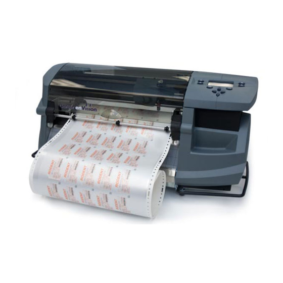
Introduction Thank you for purchasing the Gerber enVision plotter. The enVision is a state- of-the-art plotter designed for use with the GRAPHIX ADVANTAGE and other sign design systems using the HPGL command set. The plotter is available in two models the enVision 750, which is 30"... -
Page 6: Manual Conventions
WARNING: A warning statement contains information which, if not observed, could result in personal injury. Customer support If you require assistance installing or operating your enVision plotter, contact your distributor or Gerber Field Service at: 800-828-5406 (in the USA) 860-645-2448 (fax) The Gerber web site address is www.gspinc.com. -
Page 7: Getting Started
Failure to repack the enVision plotter with the original packaging materials may result in damage to the unit during shipping. Gerber is not liable for shipping damage due to improperly packed units. If you do not have the proper packaging materials, contact Gerber Field... -
Page 8: Connecting The Plotter To The Computer
enVision Owner’s Guide Connecting the plotter to the computer The enVision is equipped with a null modem serial interface cable and power cord. Connect the 25-pin connector end of the serial interface cable to the connector on the plotter and tighten the screws. Connect the other end of the serial cable (9-pin connector) to a the computer COM port. -
Page 9: Turning On The Plotter
Getting Started Turning on the plotter When you turn on power, the plotter performs a check and initialization sequence. The three closely-spaced material alignment pins move to the up position, the tool head taps the right stop, then moves about 2" (5.08 cm) to the left. -
Page 10: Updating Ga Software
enVision Owner’s Guide Updating GA software The enVision plotter is shipped with four 3.5-inch disks. One set of three disks is service pack 3, which is used to update GA version 6.2 so that you can add the enVision plotter and allow it to be fully supported and controlled by GA. The single disk is a driver disk which allows you to add the enVision to your list of available plotters if your GA is version 6.0 or earlier. -
Page 11: Using The Control Panel And Menus
Getting Started From the Devices box, click on enVision 750 or 375 to highlight it. If more than one plotter is connected to your system, highlight the enVision, then click Preferences to set the enVision as the default plotter. Click on the port to which the plotter is connected (COM1, COM2, COM3, or COM4) in the Ports box. - Page 12 enVision Owner’s Guide The message display shows menus, instructions, system and job status, and messages. Each menu has a title (for example, MAIN MENU). You step through menus by pressing function keys. The F1, F2, F3, and F4 function keys select other menus and change parameter values or settings.
-
Page 13: Loading Material
Getting Started Loading material The enVision uses the same punched vinyl film, papers, and masks as all Gerber plotters. Always insist on Gerber-authorized materials for highest quality. Note: The illustrations for loading material depict the enVision 750 plotter. Loading material in the enVision 375 is the same except for the first three steps (putting the material on a vinyl roll shaft and installing the shaft on the plotter stand). - Page 14 enVision Owner’s Guide For the enVision 750 only, position the roll of material on the stand by inserting the vinyl roll shaft tube into the slots of the stand as shown below. Press F4, HOME. The three closely-spaced material alignment pins rotate to the up position and the tool head reorients itself.
- Page 15 Getting Started Open the bails and the front material guide tube by simultaneously pulling the bail handles forward and down away from the front of the plotter. Bail Front material guide tube Bail handle Open the rear material guide tube by lifting it up. (See the illustration below.) Pull the material up toward the plotter, feeding the material from back to front as shown in the illustration below, ensuring that the material is...
-
Page 16: Installing Tools
Installing a tool Changing the knife blade Note: The GERBER EDGE eyepiece, used to align the knife with the cutter registration mark printed on the material, is also installed in the tool head the same way as the tools. For more information on using the plotter with the EDGE, refer to the paragraph "Using the enVision with the EDGE.”... - Page 17 Getting Started Adjusting the blade exposure to the proper amount is a trial and error process. You adjust the blade exposure visually, then perform a hand-held test cut on the material you will be cutting. Evaluate the results, adjust the blade in or out, and perform another hand-held test cut.
-
Page 18: Installing A Tool
enVision Owner’s Guide Installing a tool After you adjust or verify the knife blade exposure: Move the tool head to the middle of the plotter by pressing a slew key. Open the tool clamp by turning the latch fastener counterclockwise and gently pulling the clamp open. -
Page 19: Changing The Knife Blades
Getting Started Close the clamp and secure it by turning the latch fastener clockwise. Changing the knife blades Blades are available in 30°, 45°, and 60° angles. The 30° and 60° blades are designed for cutting thin and thick materials respectively; the 45° blade is designed for most materials. - Page 20 enVision Owner’s Guide Put in the new blade using tweezers. Press the tip lightly with the flat of your fingernail to ensure that it is all the way in. Put the cap back on carefully and turn it clockwise. Adjust the blade further as needed by following the directions in the previous paragraph, “Adjusting the knife blade exposure.”...
-
Page 21: Envision Overview
Overview Both Gerber enVision plotters have many features that make them easy and convenient to use: The enVision 750 draws, cuts, and pounces designs up to 27.25 inches (692.15mm) high. Using the GRAPHIX ADVANTAGE system Panel feature, the enVision can cut text or graphics in strips up to 96 feet long (29 meters) and 27.25 inches (692.15mm) high. -
Page 22: The Plotting Process
Material selection The plotter firmware contains a table of materials (called rule sets) with corresponding tool settings for cutting Gerber materials. When you select the material you plan to cut in the plotter Settings Menu, you automatically set the factory default tool settings for that material. A rule sets guide chart is provided on reference cards in the back of this manual. -
Page 23: Using The Envision With Ga
enVision Overview Using the enVision with GA The enVision can be completely controlled from the GA version 6.2 (and higher) plot program by using controls in the Plotter Settings dialog box. Use of this dialog box is explained in the GRAPHIX ADVANTAGE Reference Volume 1 manual. -
Page 24: Using The Envision With The Edge
Using the enVision with the EDGE The enVision 375 is capable of cutting EDGE printed jobs as described in the GERBER EDGE Owner's Guide. The following additional capabilities are provided when cutting with the enVision plotter: When the Plotter Prompts check box is turned off in the Plotter Settings dialog box, the job starts when you press Start Job (F1 on the enVision control panel). -
Page 25: Plotting Jobs
Plotting Jobs You can send a job to the plotter to be output with a pen, a pounce tool, or a knife. Jobs sent to the plotter are held in the plotter’s memory. The Job Status changes from , and blinks. -
Page 26: Plotting A Single Job
enVision Owner’s Guide Plotting a single job Use Single mode to plot a single job. Single mode allows you to: change material between jobs pen plot using paper before cutting vinyl reposition the start of the next job Each job plots and then waits for you to press Start-Job again to begin the next job. -
Page 27: Plotting Multiple Jobs
Plotting Jobs The plotter displays the vinyl type and color required by the job. This information enables you to verify that you have the correct material loaded for the job. This screen only appears if you are using GA version 6.2 and the Plotter Prompts checkbox turned on. - Page 28 enVision Owner’s Guide Note: If you press F1 before sending the job, it starts immediately when received by the plotter. In this case, you must load the material and install the tool before you send the jobs to the plotter. (See “Running multiple jobs automatically”...
-
Page 29: Running Multiple Jobs Automatically
Plotting Jobs Running multiple jobs automatically In Multi mode, if you press F1, Start-Job before sending a job to the plotter, the job will begin as soon as the plotter receives it without requiring another key press, provided the following conditions are met: Material has been loaded and a tool is installed. -
Page 30: Canceling A Job
enVision Owner’s Guide Opening the cover has the same effect as pressing the Pause-Job command. With the cover open, you can use the slew keys to move the material so that you can view the job. Once the cover is closed, you can re-start the job by pressing F1 and the tool returns to where it paused. -
Page 31: Missing Tool Message
Plotting Jobs Missing tool message If no tool is loaded in the plotter, when it is first turned on the plotter displays a message telling you that there is no tool loaded. If you start the job anyway, the message disappears and the job starts. The message is not repeated even if you send another job. -
Page 32: Choosing Tool Settings
enVision Owner’s Guide Choosing Tool Settings As previously stated, cutting accuracy and weeding ease depend on matching the tool settings to the material being cut. Tool settings are: force corners speed acceleration Normally, tool settings are automatically set using the rule sets in the GA as previously described (Use Settings check box in the Plotter Settings dialog box). -
Page 33: Fine Tuning The Envision
Choosing Tool Settings If necessary, you can modify the force and corners settings right in the Settings menu. These modifications to the factory defaults will remain in effect for that material until you: manually reset the modifications to zero press default in the Settings menu to return the settings for that material back to the factory settings Note: Tool settings sent from GRAPHIX ADVANTAGE will override enVision tool settings during a job unless this feature is turned off either in GA or in the... -
Page 34: Adjusting The Force
enVision Owner’s Guide Pressing the F1 (or F2) key would cause the bar graph to move in the opposite direction, retracting toward the zero point one click for each press. When it reaches the zero point, the factory default has been reset. Continued pressing of the F1 or F2 key will extend the bar graph to the left of the zero point and reduce the factory default by the number of clicks that F1 is pressed. - Page 35 Choosing Tool Settings To adjust the force Press F3, SETTINGS. On the Settings menu, press F4, FORCE. (Scotchcal 220 is shown as an example only.) Note: Pressing F1, (default) on the Settings menu will resets all of the tool settings only for the selected material to the factory presets. Note: This change in tool force applies only to the material shown in the menu above.
-
Page 36: Corners
enVision Owner’s Guide Corners In swivel blade technology, the knife tip is always slightly behind the center of the tool holder and the knife offset is the distance between the knife center and the knife tip. Adjusting the amount of corner rounding in the firmware tells the plotter to compensate for this distance. - Page 37 Choosing Tool Settings The corners adjustment in the example at the left is too small. In this case, what should be a square corner is not well formed because the plotter did not cut far enough before turning the corner. To adjust the corners On the Settings menu, press F2, Corners.
-
Page 38: Advanced Envision Functions
enVision Owner’s Guide Advanced enVision Functions Previous sections presented information on basic enVision operations such as loading material, installing tools, plotting a job, and choosing tool settings. This section provides information about additional enVision functions including: repeats material pull-down pouncing customizing tool settings factory default settings communications... - Page 39 Advanced enVision Functions Send a job to the plotter and plot the job. When the job finishes, the job status displays if you are running in Single mode and if you are running in Multi mode. To repeat a job Press F3 while holding down the ENTER key for the Operational Setup menu.
-
Page 40: Material Pulldown
enVision Owner’s Guide Material pulldown Prior to plotting, the plotter unrolls (pulls down) a specific length of material from the supply roll. This is an automatic feature that prevents pulling the material directly from the roll at high speeds during the job which could lead to poor cut quality. -
Page 41: Pouncing
Pouncing creates a perforation in the material instead of cutting or drawing on it. It requires a special Gerber tool that can be purchased separately. The pounce tool looks like an awl (or a sewing needle) and is driven down into the paper, then moved to make a small rip in the paper. - Page 42 enVision Owner’s Guide Choose the pounce pattern you want to use: short, medium, long, or custom. (If you choose custom, you must choose the pattern length and the percent down.) Setting Pattern Length Percent down Short 0.050" (1.27 mm) Medium 0.200"...
-
Page 43: Turning Off Pouncing
Advanced enVision Functions Press F3 to step through the available pounce patterns: , and back to . Or press F4 to step through them in reverse order. Press ENTER to record the setting and return to the MISC Settings menu. Setting Pattern Length Percent down... -
Page 44: Tool Settings
In addition to correct blade exposure, there are four tool settings that affect the quality of the cut: force, acceleration, speed, and corners. The enVision comes with default settings for many Gerber material types that specify the optimal force, acceleration, speed, and corners. The following paragraphs explain how to change these settings. -
Page 45: Overriding Rules
Overriding rules GRAPHIX ADVANTAGE contains rules that set a combination of acceleration, speed, force, and corners for each different Gerber material. When you send a job from GRAPHIX ADVANTAGE to the enVision, the rule for the chosen material is sent with it and, for the duration of that job, will override any settings you have made at the plotter. -
Page 46: Customizing Tool Settings
Owner’s Guide Customizing tool settings The enVision is pre-set with specific tool settings for each type of Gerber material that might be cut. You may occasionally wish to cut a material with different settings. The Settings menu allows you to modify only the Force and Corner adjustment for the selected material. - Page 47 Advanced enVision Functions Worn blades require a higher tool force setting. You may wish to increase the tool force after many cuts. However, before increasing tool force, check to see if the blade is in good condition. Increasing the force may also necessitate changes for the corners and speed settings to maintain a good cut quality.
-
Page 48: Setting Corners
enVision Owner’s Guide Note: Keep in mind that adjustments made to force in the Settings menu (see “Adjusting the force” on page 30) are added to the new force setting you have just made. If you don’t want that to happen, you must go back to Force in the Settings menu and return the bar graph to its zero point. -
Page 49: Setting Acceleration
Advanced enVision Functions Setting acceleration The acceleration setting represents how fast the tool head and material will get up to the speed setting. High acceleration will make the tool head and material move with quick, sudden motion. Low acceleration moves are gentle and smooth. -
Page 50: Setting Speed
enVision Owner’s Guide Press ENTER to accept the value and return to the Current Settings menu. Setting speed The speed setting represents the maximum speed of the material and tool head. Low speeds are useful for cutting intricate or small graphics. Higher speeds are used for plain or larger graphics. -
Page 51: Factory Default Settings
Advanced enVision Functions Factory default settings There are three levels of factory default settings that can be restored on the enVision: the default settings for the current material (See “Choosing Tool Settings” on page 28.) the default settings for all materials (below) the defaults for all settings (below) Reloading factory defaults for all materials Note: All materials are reset to default settings. -
Page 52: Communication Settings
enVision Owner’s Guide Speed 36 in/sec Pulldown 12 in Acceleration HPGL units 0.01 mm/unit Force 3 oz Use rule sets Corners 0.020 in Pounce Type Scotchcal 220 material Selected Baud 9600 Run mode Single Data Text Display English Stop Parity None Communication settings The communication settings on the plotter are preset at the factory to... - Page 53 Advanced enVision Functions To reset the number of data bits, press F1, DATA BITS. Press F3 or F4 to change the Data Bits setting. You can choose from data bits. Press ENTER to record the setting and return to the Communications menu.
-
Page 54: Testing
enVision Owner’s Guide If you want to reset the stop bit, press F3, STOPS. Press F3 and F4 to change the number of Stop bits. You can choose between and . Press ENTER to record setting and return to the Communications menu. -
Page 55: Wagon Wheel Test Plot
Advanced enVision Functions Wagon wheel test plot The wagon wheel test plot is a pen plot and is used to check the X, Y, and, Z axes. Once the job is enabled it will continue to be available until it is disabled. If the plotter is in Single mode, it will plot one test pattern and stop. - Page 56 enVision Owner’s Guide Press F2, Plot wheel. displays. Press any key. displays. Press any key. displays. Press F1, Start-Job. The plotter generates the Wagon Wheel test plot. If the plotter is in Single mode, as above, it will stop when one test pattern has been plotted. If it is in Multi mode, it will continue to plot one test pattern after another until you press CANCEL to stop it or switch back to single.
-
Page 57: X08 Cut Test
Advanced enVision Functions Press F3, DISABLE. You see a message that the test job has been disabled. Press any key to return to the MAIN MENU. The test job can also be disabled by turning the power off and then on. X08 cut test The X08 cut test also tests the X, Y, and Z axes. - Page 58 enVision Owner’s Guide Press F1, TEST JOBS. Press F1, X08-Cut. displays. Press any key. displays. Press any key. displays. Press F1, Start-Job. The plotter generates the X08 test pattern. If the plotter is in Single mode, as above, it will stop when one test pattern has been cut. If it is in Multi mode, it will continue to cut one test pattern after another until you press CANCEL to stop it.
- Page 59 Advanced enVision Functions Perform the following steps to disable the test job. From the ** Test Job: Active ** screen, Press F3 while holding down the ENTER key for the Operational Setup menu. Press F2, TEST. Press F1, TEST JOBS. Press F3, DISABLE.
-
Page 60: Troubleshooting
enVision Owner’s Guide Troubleshooting Your enVision plotter will provide you with trouble-free operation and productivity for many years to come. However, if you experience an unexpected or unusual sequence of events, use this section to address: Version number Error Conditions Common Problems/Solutions Version number Should a problem occur you may be asked to check the firmware version... -
Page 61: Error Messages
The control panel displays "System Error" followed by an error code number. The error code numbers and their meanings are listed below. Call Gerber Field Service at 800-828-5406 or 860-643-1515, or fax 860-645-2448... - Page 62 enVision Owner’s Guide Error/Failure Meaning Correction Y Axis Encoder Failure Check encoder and power Check for obstructions and retry. Call connectors. Field Service if retry fails. Servo System Halt SYSOK line not asserted. Contact Field Service. X Axis Overload Material movement is jammed Unjam X axis.
-
Page 63: Common Problems/Solutions
Troubleshooting Common problems/solutions This chart of symptoms can help identify the possible problem and the probable adjustment procedure. Refer to the table below for help when solving a problem. Symptom Recommended Procedure No power Check power cable, plugs, fuses, and the ON/OFF switch. Missing tool You can choose to ignore the warning without consequences. -
Page 64: Maintenance
enVision Owner’s Guide Maintenance This section includes instructions for routine cleaning and fuse replacement. Routine cleaning/replacement Routine cleaning should be done weekly or after every 80 hours of use, whichever occurs first. Use a clean, lint-free cloth and 97% or greater isopropyl alcohol to clean dust and debris. -
Page 65: Sprockets And Bails
Maintenance Sprockets and bails X axis material Bail support surface Sprocket Clean the left and right bail wheels and the bail. The left sprocket assembly floats on a pin. Clean the pin so that the sprocket floats freely. Inspect the pins of the sprockets for adhesive buildup from the use of vinyl films. -
Page 66: Y Axis Beam And Tool Assembly
enVision Owner’s Guide Y axis beam and tool assembly CAUTION: Allowing a build-up of dirt to accumulate on the metal ways can shorten the life of the moving parts and can adversely affect cutting quality. (The metal ways are the four shiny metal surfaces the bearings ride on: two on the top , and two on the bottom.) Y axis carriage Bearings... -
Page 67: Material Support
Maintenance Material support There are two areas that support material: one on the rear of the plotter and one on the front. The supporting area on the front contains a cut off mat for cutting off material. Clean this mat with a lint-free cloth and isopropyl alcohol. Stripper plate cut off mat Stripper plate... -
Page 68: Fuse Replacement
enVision Owner’s Guide Remove the protective backing from the replacement strip and insert it into the groove. Press the cut strip firmly along its entire length to assure tight, even adhesion. The strip must be flat for the entire length. Fuse replacement The enVision has both AC and DC fuses. -
Page 69: Dc Fuse Replacement
Maintenance Find the small tab at the right edge of the fuse carrier just to the left of the power cord receptacle. Insert a flat-tip screwdriver under the tab and gently pry outward, loosening the carrier. Pull out the fuse carrier. Remove any blown fuse. - Page 70 enVision Owner’s Guide Insert a flat tipped screwdriver into slotted cap, as shown in the illustration, and rotate counterclockwise about ½ turn. Cap will release spring outward. Take out cap and remove fuse. Remove any blown fuse. The fuse rating is marked on the fuse itself. Be sure to replace a blown fuse with a new fuse of identical size and rating.
-
Page 71: Hpgl Support
enVision Owner’s Guide HPGL Support This appendix provides the HPGL commands supported by the enVision. It also describes a test file you can use to verify enVision operation. The default HPGL plotter unit for the enVision plotter is 0.01mm (0.0003937 inch). -
Page 72: Hpgl Test File
enVision Owner’s Guide PU - Pen Up move PD - Pen Down move PG; - Page (End of Job) This command is used as the end-of file marker. Failure to use the page command could result in the job stopping with the pen down or successive jobs overcutting an earlier one. -
Page 73: Changing The Hpgl Units
Index Press F1 to Start the job. Each time the file is sent to the plotter it should plot a one-inch square and advance .1 inch. Changing the HPGL units The enVision is factory set with an HPGL unit of 0.010 mm. You can change it to 0.025 mm by following this procedure. - Page 74 enVision Owner’s Guide Index Force ........... 40, 42 adjusting.......... 30, 31 Function keys..........8 Acceleration.........40, 45 Fuses, replacing ........65 Adjusting corners ..........32 force............30 Autofit ............26 pouncing ..........37 software, loading........6 using with the plotter ......19 Bail handles ..........
- Page 75 Index using with the EDGE ......20 version number ........56 Maintenance ..........61 Plotter Prompts check box ......20 Manual conventions........2 Plotter Settings dialog box......19 Material Plotting loading ............ 9 a single job..........22 overriding rule sets ....... 41 jobs............
- Page 76 enVision Owner’s Guide speed, setting ........46 Vinyl strip, replacing ........ 64 viewing settings ........42 Troubleshooting........56 Wagon wheel test job........ 51 canceling ..........52 Unpacking ..........3 Web site address ......... 2 Use Settings check box......19 X08 test job..........53 Version number ........
- Page 78 Owner’s Guide COMMENT CARD Please take a moment to complete this questionnaire and mail it to Gerber Scientific Products or fax it to 860-648-8214. We are working hard to produce documentation that will meet your needs. We value your comments.
- Page 79 NO POSTAGE NECESSARY IF MAILED IN THE UNITED STATES BUSINESS REPLY MAIL FIRST CLASS PERMIT NO. 001 South Windsor, CT POSTAGE WILL BE PAID BY ADDRESSEE ATTN: TECHNICAL COMMUNICATIONS DEPARTMENT Gerber Scientific Products, Inc. 83 Gerber Road South Windsor, CT 06074-9864...
- Page 80 151 Batson Drive Manchester, CT 06040 U S A P67606A Rev B...