
Related Manuals for Fire-Lite 411


Summary of Contents for Fire-Lite 411
- Page 1 Digital Alarm Communicator/Transmitter Document #50921 12/09/2008 Rev. P/N 50921:E ECN 08-879 © 2009...
-
Page 2: Fire Alarm System Limitations
While a fire alarm system may lower insurance Fire Alarm System Limitations rates, it is not a substitute for fire insurance! An automatic fire alarm system–typically made up of age of flammable materials, etc.). smoke detectors, heat detectors, manual pull stations, Heat detectors do not sense particles of combustion and audible warning devices, and a fire alarm control panel with alarm only when heat on their sensors increases at a... -
Page 3: Installation Precautions
Adherence to the following will aid in problem-free Installation Precautions installation with long-term reliability: WARNING - Several different sources of power can be Like all solid state electronic devices, this system may connected to the fire alarm control panel. Disconnect all operate erratically or can be damaged when subjected to sources of power before servicing. - Page 4 Notes 411 Communicator Document #50921 Rev. E 12/09/2008 P/N 50921:E...
-
Page 5: Table Of Contents
Product Description CHAPTER 1: ........................8 Product Features ............................8 411 Digital Communicator ..........................8 Specifications ..............................9 Circuits ................................10 Power Requirements ..........................10 Channels/Inputs ............................. 10 Primary and Secondary Phone Lines ..................... 10 Earth Ground ............................10 Controls and Indicator ........................... - Page 6 Handset/Speaker Connection ..........................37 Central Station Communications CHAPTER 4: ....................38 Format Selection Addresses ( 20 and 50) Programming ................39 Format Selection Address Explanation ......................40 Transmittal Priorities ..........................41 Ademco Contact ID Format Event Code Description ................42 Compatible UL Listed Receivers ........................
- Page 7 This digital communicator has been designed to comply with standards set forth by the following regulatory agen- cies: • Underwriters Laboratories Standard • NFPA 72 National Fire Alarm Code • CAN/ULC - S527-M99 Standard for Control Units for Fire Alarm Systems Before proceeding, the installer should be familiar with the following documents.
-
Page 8: Chapter 1: Product Description
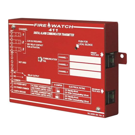
Product Description Product Description CHAPTER 1 The 411 is a three input/channel, dual line, digital alarm communicator transmitter which can be used as a slave com- municator with UL listed fire and nonfire control panels. The three inputs are compatible with normally open relay contacts, require End-Of-Line (EOL) resistors, are supervised and are fully programmable. -
Page 9: Specifications
Specifications • LED for Communication Fail (visible with cover on) • Piezo sounder • Local piezo silence switch which silences onboard piezo sounder (accessible without removing cover) • Real time clock • Extensive transient protection • One Form-C relay, fully programmable to activate for the following conditions: fire alarm host control panel trouble fire supervisory... -
Page 10: Circuits
Circuits Circuits The 411 circuit board utilizes surface mount technology and contains a MicroController Unit (MCU), dual modular phone line jacks, piezo sounder and two connectors for input, output and power wiring. 1.3.1 Power Requirements Voltage for the digital communicator may be a power-limited, filtered, nonresettable nominal 12 VDC [11.2 to 12.4 VDC (UL tested range: -15%, +10%)] or nominal 24 VDC [21.3 to 24.0 VDC (UL tested range: -15%, +10%)]. -
Page 11: Digital Communicator Operation
Digital Communicator Operation 411 Piezo Sounder • The 411 piezo sounder is used to locally annunciate DACT troubles. DACT troubles include input channel open circuit, phone line 1 or 2 voltage fault, phone number 1 or 2 communication fault, total communication failure and communications disabled. -
Page 12: Digital Communicator
Before connecting the 411 to the public switched telephone network, the installation of two RJ31X jacks is necessary. The following information is provided if required by the local telephone company: Manufacturer: Fire•Lite Alarms Inc./Notifier One Fire-Lite Place Northford, CT 06472 Product Model Number: 411 FCC Registration Number: OAAUSA-25431-AL-E Ringer Equivalence 0.5B... -
Page 13: Telephone Company Rights And Warnings
Telephone Requirements and Warnings 1.6.3 Telephone Company Rights and Warnings: The telephone company, under certain circumstances, may temporarily discontinue services and/or make changes in its facilities, services, equipment or procedures which may affect the operation of this digital communicator. How- ever, the telephone company is required to give advance notice of such changes or interruptions. -
Page 14: Operational Modes
Operational Modes Operational Modes 1.7.1 Normal Mode Normal Mode is the standard mode of operation in which the 411 digital communicator monitors the host control panel status as well as telephone line voltage and other internal circuits. In addition to locally annunciating commu- nication fail, the digital communicator transmits system status information to UL listed central station receivers. -
Page 15: Chapter 2: Installation
Installation Installation CHAPTER 2 Mounting Options The 411 with enclosure may be mounted in the cabinet of the Fire•Lite/Notifier control panel which is being monitored or in any enclosure UL listed for fire protective use. When using with other than Fire•Lite/Notifier control panels, the 411 may be mounted in any enclosure UL listed for fire protective use. -
Page 16: Typical Facp Connection To 411
Input Channels Typical FACP Connection to 411 FIGURE 2-2: Channel 1 Channel 2 Channel 3 24 VDC nonresettable power Supervisory Relay J4 Not Installed Alarm Relay Trouble Relay 2.2K EOLS P/N 27070 Typical FACP MS-9200 Each input channel monitors a normally open device and may be programmed as follows: •... -
Page 17: Style B Channel Connections
Output Circuits Channel Labels Note that space is provided for labeling the function of each channel. Write the function that has been programmed for each channel in the white boxes located to the right of the channel designator. Style B Channel Connections FIGURE 2-3: Channel/Input Labels Inputs are power-limited,... -
Page 18: Telephone Circuits
Telephone Circuits Telephone Circuits Provision to connect two independent telephone lines is available via two telephone jacks labeled PH1 (Primary) and PH2 (Secondary). Telephone line control/command is possible via double line seizure as well as usage of an RJ31X style interconnection. (RJ31X jacks must be ordered separately). CAUTION: It is critical that the 411 be located as the first device on the incoming telephone circuit to properly function. -
Page 19: Optional Programmer
Optional Programmer Optional Programmer The optional Fire-Watch 411 Series DACT Programmer is used to: switch between the digital communicator's five Modes of operation set the digital communicator's 24 hour internal clock in Real-Time Clock Mode program the 411 digital communicator in Program Mode test the telephone lines interconnect in Troubleshoot Mode return all digital communicator programming to the factory default settings in Default Mode To use the 411 Series DACT Programmer:... -
Page 20: Ul Power-Limited Wiring Requirements
UL Power-limited Wiring Requirements UL Power-limited Wiring Requirements The three 411 input channels are power-limited circuits. Power supplied to the 411 must be power-limited 12 or 24 volts, filtered and nonresettable. Do not connect nonpower-limited wiring to any circuits on the 411. 411 Communicator Document #50921 Rev. -
Page 21: Modes Of Operation
Modes of Operation Modes of Operation CHAPTER 3 The 411 digital communicator has five operational modes: • Normal Mode • Real Time Clock Mode • Program Mode • Troubleshoot Mode • Default Mode The operational mode for the digital communicator is Normal Mode. The operator is able to switch between any modes of operation provided no alarm events are active in the system. -
Page 22: Programmer Key Functions
Normal Mode The 411 can be switched from Normal Mode to any other Mode, provided no channel programmed for fire alarm or fire supervisory is active, that is, in alarm (shorted). The Fire-Watch 411 Series DACT Programmer must be con- nected to the 411 in order to change from mode to mode. -
Page 23: Programmer Display
Real Time Clock Mode 1st EVENT KEY This key, along with the UP and DOWN arrow keys, are used only in Program Mode. Press the 1st EVENT key at any time to display the first program memory address and its content. The following may be displayed on the Programmer: 00_F (address)(data) - Page 24 Real Time Clock Mode If an incorrect key is entered, reenter the proper 4-digit code before pressing the [ENTER/STORE] key. Note that as information is entered into the 411, the digits will scroll across the Programmer display from right to left. ___2 __25 _252...
-
Page 25: Program Mode
Program Mode To exit Real Time Clock Mode before completing clock programming, press the MODE key, followed by the 4-digit code for an alternate mode and then the [ENTER/STORE] key. During Real Time Clock Mode, if no key is pressed within 10 minutes, the communicator will revert to Normal Mode. -
Page 26: Dact Programming
Program Mode Once in Program Mode, the digital communicator will: Activate relay which is defaulted to DACT trouble Ignore all other keys other than those mentioned in this section Display 00_F on the Programmer display Continue to communicate any events not previously acknowledged at a central station prior to entering Programming Mode While in Program Mode, the first three locations on the left of the Programmer display represent the memory address and the last location (farthest right) represents the contents of the memory address. - Page 27 Program Mode Primary Central Station Number Communication Format (20) One location is needed to select the Communication Format to the primary phone number. Address 20 is used for this purpose. The factory default setting for this address is 'E', which is Contact ID Format. You may enter '0' through 'D' in place of the default, then press [ENTER/STORE].
-
Page 28: Ademco Contact Id Format - Primary
Program Mode Ademco Contact ID Format Primary Central Station Event Codes If 'E' is entered for address 20, the following data is automatically programmed for the Primary Central Station phone number event codes. Enter '000' for the Setting to disable the report to the Central Station. The Channel # is not programmable. -
Page 29: All 3+1, 4+1 And 4+2 Expanded Formats - Primary
Program Mode 4+2 Standard and 4+2 Express Formats - Primary TABLE 3-2: Address Description Setting 190 - 191 Primary # System Test Message 192 - 193 Primary # System Abnormal Test Message 194 - 195 not used 196 - 197 not used 198 - 199 not used... - Page 30 Program Mode Primary Central Station Number 24 Hour Test Time (25 - 28) Use military time when entering the 24 hour 'test' time. The 24 hour test report to phone number 1 takes up four locations, from addresses 25 - 28. The default is 00:00 (12:00 midnight). The limits for each location are as fol- lows (do not use values of A - F as entries).
-
Page 31: Ademco Contact Id Format - Secondary
Program Mode Secondary Central Station Number Communication Format (50) One location is needed to select the Communication Format to the secondary phone number. Address 50 is used for this purpose. The factory default setting for this address is 'E', which is Contact ID Format. You may enter '0' through 'D' in place of the default, then press [ENTER/STORE]. -
Page 32: 4+2 Standard And 4+2 Express Formats - Secondary
Program Mode Ademco Contact ID Format - Secondary TABLE 3-4: Channel/ Address Description Setting Input # 214 - 216 Secondary # Input Channel 1 Fault Event Code 217 - 219 Secondary # Input Channel 2 Fault Event Code 220 - 222 Secondary # Input Channel 3 Fault Event Code 223 - 225 not used... -
Page 33: All 3+1, 4+1 And 4+2 Expanded Formats - Secondary
Program Mode All 3+1, 4+1 and 4+2 Expanded Formats Secondary Central Station Event Codes If 0, 2, 3, 4, 5, 6, 7, 8 ,9, B or D is entered for address 50, the following data is automatically programmed for the Secondary Central Station phone number event codes. - Page 34 Program Mode Secondary Central Station Number 24/12/8/6 Hour Test Time Interval (59) The test report sent to the Secondary phone number may be sent every 6, 8, 12 or 24 hours. If the message is to be sent every 24 hours, leave the factory default entry of '0'. If other test report times are needed, enter 1 = 12 hour, 2 = 8 hour or 3 = 6 hour.
- Page 35 Program Mode Reserved for Future Use (68) Input Channel 1 Delay Timer (69 - 71) The Delay Timer is used to delay activation of the digital communicator when the Input Channel is activated. Input Channel 1 Delay Timer is factory set to '000' seconds for no delay. The timer may be programmed for a delay of from 0 to 179 seconds.
- Page 36 Program Mode Output Relay Function Selections (88) The Output Relay can be programmed to activate for any one of six conditions. It can be programmed to 0, 1, 2 or 4 to match one of the input channels or it can be programmed to 6 or 7 for DACT functioning. The factory default for address 88 is '7' for activation on DACT trouble.
-
Page 37: Default Mode
Default Mode Default Mode To return all program entries to their factory original settings, perform the following steps only when the system is idle (i.e. the communicator is not active) and there are no active fire alarms or fire supervisories in the system: Press the MODE key followed by the 4-digit code 3337 and press the [ENTER/STORE] key. -
Page 38: Central Station Communications
Central Station Communications Central Station Communications CHAPTER 4 The 411 digital communicator transmits system status reports to Central Stations via the public switched telephone network. Two supervised telephone line connections are made to interface the communicator to the telephone lines. Two 7-foot telephone cords P/N MCBL-7 may be used for this purpose (not supplied - order separately). -
Page 39: Format Selection Addresses ( 20 And 50) Programming
Central Station Communications The digital communicator is capable of reporting detailed messages depending upon the Format in use. Table 4-1 shows the data reporting structure for each of the pulsed formats as well as the Ademco Express Formats. Ademco Express Formats allow a typical data message to be transmitted to the Central Station in under 5 seconds. Pulsed for- mats typically require 15 to 20 seconds in comparison. -
Page 40: Format Selection Address Explanation
Central Station Communications Format Selection Address Explanation TABLE 4-2: Where: SSS or SSSS = Subscriber ID = Fire Alarm (1st digit) = Fire Alarm (2nd digit) = Channel/Input Number = Fire Alarm Restore (1st digit) RFA2 = Fire Alarm Restore (2nd digit) = Zone Trouble (1st digit) = Zone Trouble (2nd digit) = Zone Trouble Restore (1st digit) -
Page 41: Transmittal Priorities
Central Station Communications 4.0.1 Transmittal Priorities The digital communicator transmits highest priority events first. Events in terms of priority are listed below in descending order: Fire Alarm (highest priority level) Fire Supervisory System Troubles Host Panel Trouble (active input programmed for trouble) AC Fail (after delay) Channel/Input faults Telephone line fault... -
Page 42: Ademco Contact Id Format Event Code Description
Central Station Communications 4.0.2 Ademco Contact ID Format Event Code Description This section describes the various Event Codes and their messages which are available for the Ademco Contact ID Format. The reporting structure for the Ademco Contact ID Format is as follows: SSSS 18 QXYZ GG CCC Where: SSSS... -
Page 43: Compatible Ul Listed Receivers
Central Station Communications The following table contains UL listed receivers compatible with the 411 digital communicator. Compatible UL Listed Receivers TABLE 4-3: Format # (Addresses 20 and 50) 4+1 Ademco Express 4+2 Ademco Express 3+1/Standard/1800/2300 3+1/Expanded/1800/2300 3+1/Standard/1900/1400 3+1/Expanded/1900/1400 4+1/Standard/1800/2300 4+1/Expanded/1800/2300 4+1/Standard/1900/1400 4+1/Expanded/1900/1400 4+2/Standard/1800/2300... -
Page 44: Programming Sheets
Programming Sheets Programming Sheets Appendix A A.1 Digital Communicator Options Program Sheets --To enter Programming Mode, press the MODE key, 7764 and then the [ENTER/STORE] key. Addresses 00 to 19 store the Primary Central Station phone number. Enter 'F' to represent the end of number. Primary Central Station Communication Format: Valid entries are 0 to 9 and A to F. - Page 45 Programming Sheets Input Channel 3 Delay Timer. Enter 0 - 179 seconds delay. Factory default is '000' for no delay. Does not delay Input Channels programmed for fire functions. Future use. Touchtone/Rotary Select for Primary Phone. Enter '0' for touchtone dialing; '1' for rotary dialing. Make/Break Ratio for Primary Phone.
-
Page 46: Digital Communicator Options Program Sheet (Factory Defaults)
Programming Sheets A.2 Digital Communicator Options Program Sheet (Factory Defaults) --To enter Programming Mode, press the MODE key, 7764 and then the [ENTER/STORE] key. Addresses 00 to 19 store the Primary Central Station phone number. Enter 'F' to represent the end of number. Primary Central Station Communication Format: 'E' for Ademco Contact ID Format. - Page 47 Programming Sheets Touchtone/Rotary Select for Secondary Phone. '0' for touchtone dialing. Make/Break Ratio for Secondary Phone. '0' for 67/33 ratio. Future Use. Future Use. Output Relay Enable. ‘1’ to enable relay. Output Relay Function Selection. ‘7’ for activation on DACT trouble. Trouble Call Limit.
-
Page 48: Event Codes/Transmission Format Programming Sheets
Event Codes/Transmission Format Programming Sheets Event Codes/Transmission Format Appendix B Programming Sheets --To enter Programming Mode, press the MODE key, 7764 and then the [ENTER/STORE] key. B.1 4+2 Standard & 4+2 Express Formats Primary Central Station B.2 4+2 Standard & 4+2 Express Formats Secondary Central Station 411 Communicator Document #50921 Rev. -
Page 49: 4+2 Standard & 4+2 Express Formats Primary Central Station
Event Codes/Transmission Format Programming Sheets --To enter Programming Mode, press the MODE key, 7764 and then the [ENTER/STORE] key. B.3 4+2 Standard & 4+2 Express Formats Primary Central Station B.4 4+2 Standard & 4+2 Express Formats Secondary Central Station 411 Communicator Document #50921 Rev. -
Page 50: All 3+1, All 4+1 And 4+2 Expanded Formats For Primary Central Station
Event Codes/Transmission Format Programming Sheets --To enter Programming Mode, press the MODE key, 7764 and then the [ENTER/STORE] key. B.5 All 3+1, All 4+1 and 4+2 Expanded Formats for Primary Central Station B.6 All 3+1, All 4+1 and 4+2 Expanded Formats for Secondary Central Station B.7 All 3+1, All 4+1 and 4+2 Expanded Formats for Primary Central Station (Factory Defaults) -
Page 51: Ademco Contact Id Format Primary Central Station
Event Codes/Transmission Format Programming Sheets --To enter Programming Mode, press the MODE key, 7764 and then the [ENTER/STORE] key. B.9 Ademco Contact ID Format Primary Central Station B.10 Ademco Contact ID Format Secondary Central Station B.11 Ademco Contact ID Format Primary Central Station (Factory Defaults) B.12 Ademco Contact ID Format Secondary Central Station (Factory Defaults) -
Page 52: Ademco Contact Id Format Event Code Description
Ademco Contact ID Format Event Code Description Ademco Contact ID Format Event Appendix C Code Description EVENT CODE CLASSIFICATIONS ALARMS SUPERVISORY TROUBLES DISABLES/ OPEN/CLOSE TEST/ BYPASSES REMOTE ACCESS MISC. Medical Fire System Open/Close System Test Fire Sounder/Relay Remote Access Sounder/Relay Panic System Peripheral Access Control... - Page 53 Ademco Contact ID Format Event Code Description EVENT MESSAGE General Alarms - 140 140 General Alarm ALARM - General Alarm - # 141 Polling loop open ALARM - Polling Loop Open - # 142 Polling loop short ALARM - Polling Loop Short - # 143 Expansion module failure ALARM - Exp.
- Page 54 Ademco Contact ID Format Event Code Description EVENT MESSAGE System Peripheral Troubles - 330 and 340 330 System peripheral TROUBLE - Sys. Peripheral - # 331 Polling loop open TROUBLE - Polling Loop Open 332 Polling loop short TROUBLE - Polling Loop Short 333 Expansion module failure TROUBLE - Exp.
- Page 55 Ademco Contact ID Format Event Code Description EVENT MESSAGE Sounder/Relay Disables - 520 520 Sounder/Relay disable DISABLE - Sounder/Relay - # 521 Bell 1 disable DISABLE - Bell/Siren - #1 522 Bell 2 disable DISABLE - Bell/Siren - #2 523 Alarm relay disable DISABLE - Alarm Relay 524 Trouble relay disable DISABLE - Trouble Relay...
-
Page 56: Wire Requirements
Wire Requirements Wire Requirements Appendix D It is important to use the correct type of wire, wire gauge and wire run length per each 411 circuit. Reference the fol- lowing table to specify wire requirements and limitations for each digital communicator. Wire Specifications TABLE 4-4: CIRCUIT CONNECTIONS... -
Page 57: Operational Modes
Operational Modes Operational Modes Appendix E Operational Modes TABLE 4-5: CODE ACTIVITY NOTES 6676 (NORM) Returns to normal operation Fire protection is on. Program digital communicator time. 2525 (CLCK) Enters Real-Time Clock Mode Fire protection is off. Allows programming of digital communicator. 7764 (PROG) Enters Program Mode Fire protection is off. -
Page 58: Canadian Applications
Canadian Applications Canadian Applications Appendix F This section illustrates the connection of the 411 Digital Alarm Communicator/Transmitter (DACT) to an FACP for Canadian Applications. The following conditions must be adhered to in order to comply with Canadian require- ments. Only one FACP can be connected to the 411 DACT. Phone lines must exit the building in separate directions. - Page 59 Numerics LED 9 Time see DACT Line Seizure 11, 21 Power-up 25 Setting 25 Transmittal Priorities 41 Trouble Call Limit 36 AC Loss Reporting 16, 34 Modes of Operation 14, 21, 57 Trouble Resound 8 Mounting 8, 15 Troubleshoot Mode 14, 37 Backup Reporting 34 Normal Mode 14, 21 UL Power-limited Wiring 20...
- Page 60 Notes 411 Communicator Document #50921 Rev. E 12/09/2008 P/N 50921:E...
- Page 61 Notes 411 Communicator Document #50921 Rev. E 12/09/2008 P/N 50921:E...
- Page 62 Notes 411 Communicator Document #50921 Rev. E 12/09/2008 P/N 50921:E...
-
Page 63: Limited Warranty
Limited Warranty Honeywell International Inc. warrants products manufactured by it to be free from defects in materials and workmanship for eighteen (18) months from the date of manufacture, under normal use and service. Products are date stamped at time of manufacture. The sole and exclusive obligation of Honeywell International Inc. - Page 64 World Headquarters 1 Firelite Place Northford, CT 06472-1653 USA 203-484-7161 fax 203-484-7118 www.firelite.com...