Table of Contents
Advertisement
Advertisement
Chapters
Table of Contents
Troubleshooting

Related Manuals for Brother P-touch 65


Summary of Contents for Brother P-touch 65
- Page 1 SERVICE MANUAL MODEL: P-touch 65 P-touch HOME&HOBBY P-touch One...
- Page 2 SERVICE MANUAL MODEL:P-touch 65 P-touch HOME&HOBBY P-touch One...
- Page 3 © Copyright Brother 2000 All rights reserved. No part of this publication may be reproduced in any form or by any means without permission in writing from the publisher. Specifications are subject to change without notice.
- Page 4 PREFACE This publication is a service manual covering the specifications, theory of operation, disassembly/reassembly procedure, and troubleshooting of the Brother P-touch 65/P- touch HOME&HOBBY/P-touch One. It is intended for service personnel and other concerned persons to accurately and quickly provide after-sale service for our P-touch 65/P-touch HOME&HOBBY/P-touch One.
- Page 5 Chapter I. SPECIFICATIONS...
-
Page 6: Table Of Contents
CONTENTS CHAPTER I. SPECIFICATIONS 1.1 MECHANICAL SPECIFICATIONS ..................I-1 1.1.1 External Appearance....................I-1 1.1.2 Keyboard........................I-1 1.1.3 Display........................I-1 1.1.4 Printing Mechanism ....................I-2 1.1.5 Tape Cassette ......................I-2 1.1.6 Tape Cutter ......................I-2 1.2 ELECTRONICS SPECIFICATIONS ..................I-4 1.2.1 Character Generator .................... -
Page 7: Mechanical Specifications
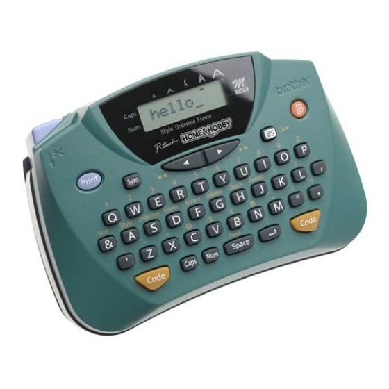
1.1 MECHANICAL SPECIFICATIONS 1.1.1 External Appearance Figure 1.1-1 External Appearance Dimensions (W x D x H) 153 mm x 105 mm x 63 mm Weight Machine proper Approx. 310 g In package 410 g or less (including dry cells and a tape cassette) 1.1.2 Keyboard Entry system... -
Page 8: Printing Mechanism
1.1.4 Printing Mechanism Print system Direct thermal printing (Fixed print head and tape feeding mechanism) Print speed 7.5 mm/second (Typical) Print head Type Thermal print head Heat generator Consists of 64 heating elements vertically aligned Size of heating element 0.136 mm wide by 0.106 mm high Character size (dots) Height x Width Standard (Small) size... - Page 9 Figure 1.1-2 Key Arrangement I - 3...
-
Page 10: Electronics Specifications
1.2 ELECTRONICS SPECIFICATIONS 1.2.1 Character Generator Internal characters U.K./French/Belgium German U.S./Canada Internal fonts HELSINKI Print buffer capacity 55 characters Phrase memory capacity None 1.2.2 Power Supply Power supply Driven by 6 dry cells Optional AC line adapter (7 VDC, 1.2A) available (Europe only) Battery type Alkaline dry cells (AM3/LR6) - Page 11 Chapter II. MECHANISMS...
- Page 12 CONTENTS CHAPTER II. MECHANISMS 2.1 THEORY OF OPERATION ....................II-1 2.1.1 Print Mechanism...................... II-1 2.1.2 Platen Setting & Retracting Mechanism ..............II-2 2.1.3 Tape Feed Mechanism.................... II-3 2.1.4 Tape Cutter Mechanism ..................II-4 2.1.5 Cutter Safety Lock Mechanism................II-5 2.2 DISASSEMBLY & REASSEMBLY..................II-6 2.2.1 Disassembly Procedure...................
-
Page 13: Theory Of Operation
2.1 THEORY OF OPERATION 2.1.1 Print Mechanism n Structure of Thermal Head This machine uses direct thermal printing. The thermal print head has a heat generator consisting of 64 heating elements which are vertically aligned as shown in Figure 2.1-1. Each heating element is 0.136 mm wide by 0.106 mm high. -
Page 14: Platen Setting & Retracting Mechanism
2.1.2 Platen Setting & Retracting Mechanism This mechanism consists of the roller holder ASSY and the roller holder setting lever (wedged lever) provided on the inside of the cassette cover. The roller holder ASSY supports the platen so that the platen can move perpendicularly to the thermal head and rotate freely. -
Page 15: Tape Feed Mechanism
2.1.3 Tape Feed Mechanism This mechanism consists of a DC motor, gear train and roller holder ASSY. When you load a tape cassette and close the cassette cover, the platen and the thermal head sandwich the tape inbetween and the platen gear becomes engaged with the gear train, as described in Subsection 2.1.2. -
Page 16: Tape Cutter Mechanism
2.1.4 Tape Cutter Mechanism The cutter mechanism consists of a cutter lever and a cutter unit in which a blade is retracted by a spring. Pressing the cutter lever pushes out the blade from the cutter unit to press the printed tape against the cutter board of the tape cassette, cutting the printed tape coming through the cutter unit and the cutter board. -
Page 17: Cutter Safety Lock Mechanism
2.1.5 Cutter Safety Lock Mechanism When the cassette cover is opened and no tape cassette is loaded, the roller holder ASSY is retracted from the thermal head with the roller holder spring (as described in Subsection 2.1.2). In this retracted position, the cutter lever stopper of the roller holder ASSY blocks the end of the cutter lever, preventing the cutter blade from coming out of the cutter unit for safety, as shown below. -
Page 18: Disassembly & Reassembly
2.2 DISASSEMBLY & REASSEMBLY n n Safety Precautions (1) You should carry out disassembly & reassembly jobs on an anti-static sheet grounded correctly. Otherwise, the LSI and other electronic devices will be damaged due to the electricity charged in your body. (2) When transporting PCBs, be sure to wrap them in conductive sheets such as aluminum foil. -
Page 19: Disassembly Procedure
2.2.1 Disassembly Procedure [ 1 ] Removing the Cassette Cover, Dry Cells, Tape Cassette, and Cutter Unit (1) Turn the machine upside down. (2) Press section "A" of the cassette cover to release the latch, and then remove the cassette cover. Figure 2.2-1 Removing the Cassette Cover (3) Remove the six dry cells, tape cassette, and cutter unit. -
Page 20: 2 ] Removing The Chassis Assy
[ 2 ] Removing the Chassis ASSY (1) Remove the four screws from the bottom cover. Figure 2.2-3 Unscrewing the Bottom Cover (2) Slightly open the bottom cover and disconnect the head flat cable from the main PCB. Figure 2.2-4 Disconnecting the Head Flat Cable II - 8... - Page 21 (3) Remove the three screws from the chassis ASSY. The FG wire also comes off. (4) Unsolder the motor lead wires from the main PCB. Figure 2.2-5 Unsoldering the Motor Lead Wires and Removing the Chassis ASSY (5) Lift the chassis ASSY up and out of the bottom cover. The cutter lever also comes off.
- Page 22 n n Disassembling the Chassis ASSY When handling the thermal head ASSY, do not touch the thermal head by hand. Otherwise, it may be damaged due to the electricity charged in your body. (1) Remove the screw from the thermal head ASSY and take off the ASSY. (2) Remove the retaining ring from the shaft of the chassis ASSY.
-
Page 23: 3 ] Removing The Sub Pcb*, Main Pcb, And Rubber Key Pad
[ 3 ] Removing the Sub PCB*, Main PCB, and Rubber Key Pad *Provided on the European version. (1) European version: Remove the two screws from the sub PCB*. Taking out the Sub PCB* Figure 2.2-7 (2) Remove the two screws from the main PCB. (3) Slightly slide the main PCB to the front, press the latches provided on the body cover outwards, and then take out the LCD by gently pulling out the main PCB and LCD flat cable. -
Page 24: 4 ] Taking Out The - And + Terminal Assys 65, +/- Terminals P1 And P3, And Battery Terminals P2
[ 4 ] Taking out the - and + Terminal ASSYs 65, +/- Terminals P1 and P3, and Battery Terminals P2 (1) Unlatch the locking pawl of the - terminal ASSY 65 with the tip of the flat screwdriver and from the bottom push the terminal ASSY up and out of the bottom cover. (2) In the same manner as in step (1), remove the +/- terminals P1 and P3. - Page 25 (4) As shown below, press the locking pawl of each battery terminal P2 with a flat screwdriver and push it out from the bottom cover. Figure 2.2-10 Taking out the Battery Terminals P2 II - 13...
-
Page 26: 5 ] Unsoldering The + And - Terminal Assys 65 And Sub Pcb Leads* From The Main Pcb
[ 5 ] Unsoldering the + and - Terminal ASSYs 65 and Sub PCB Leads* from the Main PCB *Provided on the European version. If it is necessary to separate the + and - terminal ASSY 65 or sub PCB* leads from the main PCB, unsolder them with a soldering iron. -
Page 27: Reassembly Procedure
2.2.2 Reassembly Procedure [ 1 ] Soldering the Sub PCB Leads* and the + and - Terminal ASSYs 65 onto the Main *Provided on the European version. (1) European version: Solder the four lead wires of the sub PCB* to the main PCB according to the wire ID colors as shown below. -
Page 28: 2 ] Setting The Battery Terminals P2, +/- Terminals P3 And P1, And + And - Terminal Assys 65
[ 2 ] Setting the Battery Terminals P2, +/- Terminals P3 and P1, and + and - Terminal ASSYs 65 (1) Place the bottom cover upside down. (2) Set three battery terminals P2 to the bottom cover until they snap into place, as shown below. -
Page 29: 3 ] Installing The Rubber Key Pad, Main Pcb, And Sub Pcb
[ 3 ] Installing the Rubber Key Pad, Main PCB, and Sub PCB* *Provided on the European version. (1) Place the body cover upside down. (2) Put the rubber key pad in the body cover. NOTE: Before setting the main PCB, check that there is no foreign material or dust on the key contacts of the main PCB. -
Page 30: 4 ] Installing The Chassis Assy
[ 4 ] Installing the Chassis ASSY (1) If the chassis ASSY has been disassembled, assemble the components, referring to page II-20. (2) As shown in Figure 2.2-20, fit the cutter lever onto the shaft on the chassis ASSY. (3) Put the chassis ASSY with the cutter lever back into the bottom cover. (4) Secure the chassis ASSY with three screws. - Page 31 (6) Route the wires of the + and - terminal ASSYs 65 along the four ribs provided on the bottom cover as illustrated below. (7) Connect the head flat cable to the main PCB and close the bottom cover. Figure 2.2-18 Routing the + and - Terminal ASSYs 65 and Connecting the Head Flat Cable (8) Secure the bottom cover to the body cover with four screws, taking care not to pinch the wires between the body cover and bottom cover.
- Page 32 n n Assembling the Components of the Chassis ASSY (1) Secure the DC motor ASSY to the chassis with two screws so that the motor lead wires face as shown below. (2) Set the roller holder spring onto the roller holder ASSY so that its straight end is fitted into section "A"...
-
Page 33: 5 ] Setting The Cutter Unit, Tape Cassette, Dry Cells, And Cassette Cover
[ 5 ] Setting the Cutter Unit, Tape Cassette, Dry Cells, and Cassette Cover (1) Set the cutter unit into place. (2) Set a tape cassette. (3) Load dry cells. (4) Fit hooks "X" of the cassette cover and then snap the cover into place. Figure 2.2-21 Setting the Cutter Unit, Tape Cassette, Dry Cells, and Cassette Cover II - 21... -
Page 34: 6 ] Demonstration Print And Final Check
[ 6 ] Demonstration Print and Final Check (1) Power on the machine. (2) While holding down the Code key, press the key (BS key in U.S. and Australian versions) to cancel data previously entered. (3) Power off the machine. (4) While holding down the Code and D keys, press and release the key (On/Off key in the U.S. - Page 35 Chapter III. ELECTRONICS...
- Page 36 CONTENTS CHAPTER III. ELECTRONICS 3.1 OUTLINE OF CONTROL ELECTRONICS ................III-1 3.2 MAIN PCB...........................III-2 3.2.1 Block Diagram ......................III-2 3.2.2 CPU........................III-3 3.2.3 LCD Controller......................III-3 3.2.4 Key Contacts Matrix ....................III-4 [ 1 ] Key contacts matrix....................III-4 [ 2 ] Solder points......................III-6 3.2.5 Power ON/OFF Key and Reset Circuit ..............III-7 [ 1 ] Power ON/OFF circuit ....................III-7 [ 2 ] Automatic powering-off circuit................III-8 3.2.6...
-
Page 37: Outline Of Control Electronics
3.1 OUTLINE OF CONTROL ELECTRONICS Figure 3.1-1 shows a block diagram of the control electronics of this machine. The control electronics consists of a main PCB, LCD, motor, thermal print head assembly, and sub PCB*. * Provided on the European version. n Main PCB This manages all the components including an LCD, motor, key pad, and thermal print head. -
Page 38: Main Pcb
3.2 MAIN PCB 3.2.1 Block Diagram Figure 3.2-1 shows a block diagram of the main PCB. The main PCB consists of the following: (1) CPU (including a ROM and RAM) (2) LCD controller (3) Key contacts matrix and solder points (destination switching circuit) (4) Power ON/OFF circuit (5) Motor drive circuit (6) Thermal head drive circuit... -
Page 39: Cpu
3.2.2 The CPU (#1: MN101C30A) is an 8-bit microprocessor produced by CMOS silicon gate process, which integrates a 32-kilobyte ROM and a 1.5-kilobyte RAM. 3.2.3 LCD Controller LCDC (#3: SPLC 780A2) drives the LCD in 1/8 duty and 1/4 bias levels. Figure 3.2-2 CPU and LCD Controller III - 3... -
Page 40: Key Contacts Matrix
3.2.4 Key Contacts Matrix [ 1 ] Key contacts matrix On the main PCB is a key contacts matrix that is a set of carbon-printed 43 key contact patterns. Each contact pattern has a pair of electrodes. The rubber key pad is made of high-impedance silicon rubber. As shown in Figure 3.2-3, each key on the rubber key pad consists of a key top, rubber spring, and conductive paint which functions as a switching element. - Page 41 Figure 3.2-4 Key Scan Timing Scheme and Scanning Pulse Outputs III - 5...
-
Page 42: 2 ] Solder Points
[ 2 ] Solder points Figure 3.2-5 shows a circuit diagram relating to the keyboard and solder points. Solder points 1 through 3 customize the machine for the destination (shipping country) . U.S.A./Canada Germany Belgium France England Spec. Destination Solder Points H: Solder point opened L: Solder point closed Solder points A and C are reserved for the future use for the thermal head ranking. -
Page 43: Power On/Off Key And Reset Circuit
3.2.5 Power ON/OFF Key and Reset Circuit [ 1 ] Power ON/OFF circuit Figure 3.2-6 shows a circuit diagram of the power ON/OFF key. The CPU processes the ON/OFF key state in a sequence quite different from other keys although the ON/OFF key is on the same key pad. -
Page 44: 2 ] Automatic Powering-Off Circuit
[ 2 ] Automatic powering-off circuit If you power off the machine with the ON/OFF key or you make no key entry for approx. 5 minutes, the oscillation stops so that the CPU enters the sleep mode. To cancel the sleep mode and resume the normal operation mode, press the ON/OFF key. -
Page 45: Motor Drive Circuit
3.2.6 Motor Drive Circuit Figure 3.2-8 shows the motor drive circuit of the DC motor which feeds tape. Through P10, the CPU produces a start/stop control signal to the motor drive circuit. Figure 3.2-9 shows the part of motor waveforms. #2 (BA6220) is an electronic governor IC and controls to keep the rotation speed of the motor constant even if the power source voltage (VBT) varies. -
Page 46: Thermal Head Drive Circuit
3.2.7 Thermal Head Drive Circuit Figure 3.2-10 shows the thermal head drive circuit. The print head has an integrated heat generator (consisting of 64 heating elements vertically aligned in 240 dpi) and a built-in driver IC. Synchronizing with the clock on P02, the CPU outputs print data on P00 in the serial form. - Page 47 Figure 3.2-11 Timing Chart for Thermal Head Drive III - 11...
-
Page 48: Voltage Detection Circuit
3.2.8 Voltage Detection Circuit Figure 3.2-12 shows the voltage detection circuit which is composed of a resistor network. Voltage detection circuit This circuit, which is composed of divider resistors R9 and R10, steps down the power source VAD fed from dry cells or the AC adapter and feeds the output to the A/D input port PA1 on the CPU. -
Page 49: Oscillation Circuit
3.2.9 Oscillation Circuit Figure 3.2-13 shows the oscillation circuit. This circuit contains an oscillator and generates 8 MHz frequency which acts as the CPU basic clock. The CPU divides this into half (4 MHz) to synchronize its internal operations. Figure 3.2-13 Oscillation Circuit III - 13... -
Page 50: Power Supply Circuit
3.2.10 Power Supply Circuit Figure 3.2-14 shows the power supply circuit. The 3-terminal regulator RH5RL50A stabilizes the battery output, producing the +5BV power source (5±0.125V). Figure 3.2-14 Power Supply Circuit III - 14... -
Page 51: Sub Pcb
3.3 SUB PCB 3.3.1 Sub PCB The sub PCB is provided for the European version and allows you to connect an AC adapter. Figure 3.3-1 Sub PCB Circuit III - 15... - Page 52 Chapter IV. TROUBLESHOOTING...
- Page 53 CONTENTS CHAPTER IV TROUBLESHOOTING 4.1 TROUBLESHOOTING ......................IV-1 4.1.1 Precautions ......................IV-1 4.1.2 After Repairing .......................IV-1 4.1.3 Troubleshooting Flows ...................IV-2 [ 1 ] Tape feeding failure ....................IV-2 [ 2 ] Printing failure......................IV-5 [ 3 ] Powering failure (Nothing appears on the LCD.) ...........IV-8 [ 4 ] No key entry possible...................IV-10 [ 5 ] Abnormal LCD indication ..................IV-11...
-
Page 54: Troubleshooting
4.1 TROUBLESHOOTING This section gives the service personnel some of the troubleshooting procedures to be followed if an error or malfunction occurs with this machine. It is impossible to anticipate all of the possible troubles which may occur in future and determine the troubleshooting procedures, so this chapter covers some sample troubles. -
Page 55: Troubleshooting Flows
4.1.3 Troubleshooting Flows [ 1 ] Tape feeding failure IV - 2... - Page 56 IV - 3...
- Page 57 IV - 4...
-
Page 58: 2 ] Printing Failure
[ 2 ] Printing failure IV - 5... - Page 59 IV - 6...
- Page 60 IV - 7...
-
Page 61: 3 ] Powering Failure (Nothing Appears On The Lcd
[ 3 ] Powering failure (Nothing appears on the LCD.) IV - 8... - Page 62 IV - 9...
-
Page 63: 4 ] No Key Entry Possible
[ 4 ] No key entry possible IV - 10... -
Page 64: 5 ] Abnormal Lcd Indication
[ 5 ] Abnormal LCD indication IV - 11... - Page 65 APPENDICES Circuit Diagrams A: Main PCB B: Sub PCB (for P-touch 65 and P-touch One only)
- Page 66 Appendix A. Main PCB POWER SUPPLY US Version European (UK,FR,GE,BE) Version P O W E R P O W E R P O W E R L C D E C 1 3 1 0 4 L C D R W L C D U T S - G 5 3 5 A Y V C C...
- Page 67 Appendix B. Sub PCB V B T 3 R 0 A 3 R 0 R 8 C 1 0 4 E R B 8 3 - 0 0 4 J A C K H E C 0 4 7 1 - 0 1 - 6 3 0 S E N S 1 S S 1 3 3 SUB PCB CIRCUIT...
- Page 68 May, 2000 8V2008BE0 Printed in Japan...