
Related Manuals for Fluke 87V Ex


Summary of Contents for Fluke 87V Ex
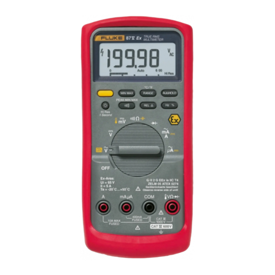
- Page 1 ® 87V Ex True-rms Multimeter Users Manual PN 2518115 December 2005 2005 Fluke Corporation. All rights reserved. Printed in USA All product names are trademarks of their respective companies.
- Page 2 LIMITED WARRANTY AND LIMITATION OF LIABILITY Each Fluke product is warranted to be free from defects in material and workmanship under normal use and service. The warranty period is one year and begins on the date of shipment. Parts, product repairs, and services are warranted for 90 days. This warranty extends only to the original buyer or end-user customer of a Fluke authorized reseller, and does not apply to fuses, disposable batteries, or to any product which, in Fluke's opinion, has been misused, altered, neglected, contaminated, or damaged by accident or abnormal conditions of operation or handling.
-
Page 3: Table Of Contents
Table of Contents Title Page Introduction........................1 Contacting Fluke ......................1 General Safety Information.....................2 ATEX Safety Information....................2 Errors and Load Restrictions ..................5 Ex-Certification Data....................6 The Meter's Features .....................8 Power-Up Options .....................15 Automatic Power-Off ....................15 Input Alert Feature ....................15 Making Measurements ....................15 Measuring AC and DC Voltage..................15 Zero Input Behavior of True-rms Meters..............17... - Page 4 87V Ex Users Manual Measuring Duty Cycle ....................31 Determining Pulse Width................... 32 Bar Graph ........................32 Zoom Mode (Power Up Option Only) ................ 33 Uses for the Zoom Mode................... 33 HiRes Mode ........................33 MIN MAX Recording Mode .................... 34 Smooth Feature (Power Up Option Only) ..............
- Page 5 List of Tables Table Title Page Electrical Symbols ......................... 7 Inputs............................. 8 Rotary Switch Positions......................9 Pushbuttons .......................... 10 Display Features........................13 Functions and Trigger Levels for Frequency Measurements..........30 MIN MAX Functions....................... 35 Approved Batteries ........................ 39 Replacement Parts ........................ 42 Specified Accessories ......................
- Page 6 87V Ex Users Manual...
- Page 7 List of Figures Figure Title Page Display Features........................13 Measuring AC and DC Voltage....................16 Low Pass Filter ........................17 Testing for Continuity......................19 Measuring Resistance ......................21 Measuring Capacitance......................23 Testing a Diode ........................25 Measuring Current......................... 27 Components of Duty Cycle Measurements ................31 Testing the Current Fuses .....................
- Page 8 87V Ex Users Manual...
-
Page 9: Introduction
True-rms Multimeter Introduction Contacting Fluke XWWarning To contact Fluke, call one of the following telephone numbers: Read "Safety Information" before you use the Meter. USA: 1-888-44-FLUKE (1-888-443-5853) Canada: 1-800-36-FLUKE (1-800-363-5853) The Fluke 87V Ex Intrinsically Safe True-rms Multimeter Europe: +31 402-675-200 (hereafter referred to as “the Meter”) is a compact and... -
Page 10: General Safety Information
87V Ex Users Manual the Meter in hazardous areas under the described General Safety Information conditions. Failure to follow the information and The Meter complies with: instructions can have dangerous consequences, or may contravene applicable legislation. EN61010-1:2001 ANSI/ISA S82.01-2004 Please take the time to read through this manual before CAN/CSA C22.2 No. - Page 11 Use only allowed accessories with this section for additional warnings on meter Meter in Ex-hazardous areas. See a listing use in hazardous areas. of allowed Fluke accessories at Do not use the Meter if it is damaged. www.Fluke.com. Before you use the Meter, inspect the Avoid using the Meter in aggressive acidic case.
- Page 12 87V Ex Users Manual Ensure the battery door is closed and Avoid working alone. latched whenever operating the Meter. When measuring current, turn off circuit power before connecting the Meter to the Replace the battery as soon as the circuit. Remember to place the Meter in battery indicator (M) appears.
-
Page 13: Errors And Load Restrictions
True-rms Multimeter ATEX Safety Information Do not use the Low Pass Filter option to Errors and Load Restrictions verify the presence of hazardous If there is any question that the safety or integrity of this voltages. Voltages greater than what is Meter is compromised, remove it from operation and the indicated may be present. -
Page 14: Ex-Certification Data
87V Ex Users Manual Measuring protected electric circuits: Ex-Certification Data Voltage-Mass (V/Ω - COM): EC-type certificate no.: ZELM 05 ATEX 0274 Ui = 65 V Uo = 10.35 V Co = 2.52 µF Ex-designation: ( II 2 G EEx ia IIC T4 Io = 4.0 mA. -
Page 15: Electrical Symbols
True-rms Multimeter ATEX Safety Information Table 1. Electrical Symbols AC (Alternating Current) Earth ground DC (Direct Current) Fuse Capacitance Diode Battery. Low battery when displayed. Continuity test or continuity beeper tone. Hazardous voltage Double insulated Do not mix with solid waste stream. Dispose Risk of Danger. -
Page 16: The Meter's Features
87V Ex Users Manual The Meter's Features Tables 2 through 5 and Figure 1 briefly describe the Meter's features. Table 2. Inputs Terminal Description Input for 0 A to 10.00 A current (20 A overload for 30 seconds maximum), current frequency, and duty cycle measurements. -
Page 17: Rotary Switch Positions
True-rms Multimeter The Meter's Features Table 3. Rotary Switch Positions Switch Position Function Any Position When the Meter is turned on, the Meter model number briefly appears on the display. AC voltage measurement Press for low pass filter (K). DC voltage measurement 600 mV dc voltage range Press for temperature... -
Page 18: Pushbuttons
87V Ex Users Manual Table 4. Pushbuttons Switch Button Function Positon Selects capacitance (Yellow) Selects temperature Selects ac low pass filter function Switches between dc and ac current Switches between dc and ac current Power-up Disables automatic power-off feature (Meter normally powers off in 30 minutes). “PoFF”... - Page 19 True-rms Multimeter The Meter's Features Table 4. Pushbuttons (cont.) Switch Button Function Positon Any switch AutoHOLD (formerly TouchHold) captures the present reading on the display. When a new, position stable reading is detected, the Meter beeps and displays the new reading. MIN MAX Stops and starts recording without erasing recorded values.
- Page 20 87V Ex Users Manual Table 4. Pushbuttons (cont.) Button Switch Positon Function Any switch Stores the present reading as a reference for subsequent readings. The display is position zeroed, and the stored reading is subtracted from all subsequent readings. (Relative mode) 2rEL Power-up...
-
Page 21: Display Features
True-rms Multimeter The Meter's Features Number Feature Indication Indicates negative readings. In relative mode, this sign indicates that the present input is less than the stored reference. Indicates the presence of a high voltage input. Appears if the input voltage is 30 V or greater (ac or dc). - Page 22 87V Ex Users Manual Table 5. Display Features (cont.) Number Feature Indication Number Feature Indication The number of segments is Amperes (amps), Microamp, Milliamp A, A, mA relative to the full-scale value of the selected range. In normal Volts, Millivolts V, mV operation 0 (zero) is on the left.
-
Page 23: Power-Up Options
True-rms Multimeter Making Measurements Power-Up Options Making Measurements Holding a button down while turning the Meter on activates The following sections describe how to take a power-up option. Table 4 includes the power-up options. measurements with the Meter. Automatic Power-Off Measuring AC and DC Voltage The Meter automatically turns off if you do not turn the XW Warning... - Page 24 87V Ex Users Manual When measuring voltage, the Meter acts approximately AC Voltage like a 10 M (10,000,000 ) impedance in parallel with the circuit. This loading effect can cause measurement errors in high-impedance circuits. In most cases, the error ˚...
-
Page 25: Zero Input Behavior Of True-Rms Meters
True-rms Multimeter Making Measurements XWWarning Zero Input Behavior of True-rms Meters To avoid possible electric shock or personal True-rms meters accurately measure distorted waveforms, injury, do not use the Low Pass Filter option but when the input leads are shorted together in the AC to verify the presence of hazardous voltages. -
Page 26: Measuring Temperature
87V Ex Users Manual Measuring Temperature Testing for Continuity The Meter measures the temperature of a type-K WCaution thermocouple (included). Choose between degrees To avoid possible damage to the Meter or to Celsius ( C) or degrees Fahrenheit ( F) by pushing C. the equipment under test, disconnect circuit W Caution power and discharge all high-voltage... - Page 27 True-rms Multimeter Making Measurements For in-circuit tests, turn circuit power off. Activates continuity beeper ˚ ˚ ˚ ˚ RANGE AutoHOLD RANGE AutoHOLD MIN MAX MIN MAX PEAK MIN MAX PEAK MIN MAX Hz % Hz % Hi Res Hi Res 1 Second 1 Second (closed)
-
Page 28: Measuring Resistance
87V Ex Users Manual Measuring Resistance The following are some tips for measuring resistance: The measured value of a resistor in a circuit is often WCaution different from the resistor's rated value. To avoid possible damage to the Meter or to The test leads can add 0.1 to 0.2 of error to... - Page 29 True-rms Multimeter Making Measurements In-Circuit Resistance Measurements Isolating a Potentiometer Circuit Power Disconnect ˚ ˚ MIN MAX RANGE AutoHOLD PEAK MIN MAX Hz % Hi Res 1 Second Isolating a Resistor Ex-Area: Ui = 65 V ZELM 05 ATEX 0274 Ii = 5 A Geräterückseite beachten! Ta = -20 C ...
-
Page 30: Using Conductance For High Resistance Or Leakage Tests
87V Ex Users Manual Using Conductance for High Resistance or To measure conductance, set up the Meter as shown for measuring resistance (Figure 5); then press Cuntil Leakage Tests the nS indicator appears on the display. Conductance, the inverse of resistance, is the ability of a The following are some tips for measuring conductance: circuit to pass current. -
Page 31: Measuring Capacitance
True-rms Multimeter Making Measurements Measuring Capacitance WCaution To avoid possible damage to the Meter or to Select the equipment under test, disconnect circuit Capacitance ˚ ˚ RANGE AutoHOLD MIN MAX power and discharge all high-voltage PEAK MIN MAX Hz % Hi Res capacitors before measuring capacitance. -
Page 32: Testing Diodes
87V Ex Users Manual Testing Diodes To test a diode out of a circuit, set up the Meter as shown in Figure 7. For forward-bias readings on any WCaution semiconductor component, place the red test lead on the To avoid possible damage to the Meter or to component's positive terminal and place the black lead on the equipment under test, disconnect circuit the component's negative terminal. - Page 33 True-rms Multimeter Making Measurements Reverse Bias Forward Bias Typical Reading ˚ ˚ ˚ ˚ MIN MAX RANGE AutoHOLD MIN MAX RANGE AutoHOLD PEAK MIN MAX PEAK MIN MAX Hz % Hz % Hi Res Hi Res 1 Second 1 Second Single Beep Ex-Area: Ex-Area:...
-
Page 34: Measuring Ac Or Dc Current
87V Ex Users Manual Measuring AC or DC Current To measure current, you must break the circuit under test, then place the Meter in series with the circuit. XWWarning The Meter's current ranges are 600.0 A, 6000 A, To avoid possible electric shock or personal 60.00 mA, 400.0 mA, 6000 mA, and 10 A. - Page 35 True-rms Multimeter Making Measurements Circuit Power: Total current to circuit OFF to connect meter. ON for measurement. OFF to disconnect meter. ˚ ˚ MIN MAX RANGE AutoHOLD PEAK MIN MAX Hz % Hi Res 1 Second Current through one component Ex-Area: Ui = 65 V ZELM 05 ATEX 0274...
- Page 36 87V Ex Users Manual If you are using the A terminal, set the rotary switch to The following are some tips for measuring current: mA/A. If you are using the mA/ A terminal, set the If the current reading is 0 and you are sure the Meter rotary switch to A for currents below 6000 A is set up correctly, test the Meter's fuses as described (6 mA), or mA/A for currents above 6000 A.
-
Page 37: Measuring Frequency
True-rms Multimeter Making Measurements Measuring Frequency The following are some tips for measuring frequency: If a reading shows as 0 Hz or is unstable, the input The Meter measures the frequency of a voltage or current signal may be below or near the trigger level. You can signal by counting the number of times the signal crosses usually correct these problems by selecting a lower a threshold level each second. -
Page 38: Functions And Trigger Levels For Frequency Measurements
87V Ex Users Manual Table 6. Functions and Trigger Levels for Frequency Measurements Approximate Function Range Typical Application Trigger Level 6 V, 60 V, ± 5 % of scale Most signals. 600 V, 1000 V High-frequency 5 V logic signals. (The dc-coupling of the L function can 600 mV ±... -
Page 39: Measuring Duty Cycle
True-rms Multimeter Making Measurements Measuring Duty Cycle frequency function, you can change the slope for the Meter's counter by pressing E. Duty cycle (or duty factor) is the percentage of time a For 5 V logic signals, use the 6 V dc range. For 12 V signal is above or below a trigger level during one cycle switching signals in automobiles, use the 60 V dc range. -
Page 40: Determining Pulse Width
87V Ex Users Manual Determining Pulse Width Bar Graph For a periodic waveform (its pattern repeats at equal time The analog bar graph functions like the needle on an intervals), you can determine the amount of time that the analog meter, but without the overshoot. The bar graph signal is high or low as follows: updates 40 times per second. -
Page 41: Zoom Mode (Power Up Option Only)
True-rms Multimeter HiRes Mode Zoom Mode (Power Up Option Only) to the right or left of zero. If an overange symbol lights (< >), press twice to set a new reference; then To use the Rel Zoom Bar Graph: continue with the adjustment. Hold down F while turning the Meter on. -
Page 42: Min Max Recording Mode
87V Ex Users Manual inputs, calculating power consumption, or estimating the MIN MAX Recording Mode percentage of time a circuit is active. The MIN MAX mode records minimum and maximum Min Max records the signal extremes lasting longer than input values. When the inputs go below the recorded 100 ms. -
Page 43: Min Max Functions
True-rms Multimeter Smooth Feature (Power Up Option Only) Table 7. MIN MAX Functions Button MIN MAX Function Enter MIN MAX recording mode. The Meter is locked in the range displayed before you entered MIN MAX mode. (Select the desired measurement function and range before entering MIN MAX.) The Meter beeps each time a new minimum or maximum value is recorded. -
Page 44: Autohold Mode
87V Ex Users Manual AutoHOLD Mode Relative Mode XWWarning Selecting relative mode ( ) causes the Meter to zero the display and store the present reading as the To avoid possible electric shock or personal reference for subsequent measurements. The Meter is injury, do not use AutoHOLD mode to locked into the range selected when you pressed determine that circuits are without power. -
Page 45: Maintenance
True-rms Multimeter Maintenance Fuse Test Maintenance If a test lead is plugged into the mA/ A or A terminal and XWWarning the rotary switch is turned to a non-current function, the To avoid possible electric shock or personal Meter chirps and flashes “LEAd” if the fuse associated injury, servicing not covered in this manual with that current terminal is good. -
Page 46: Replacing The Battery
87V Ex Users Manual Replacing the Battery Good F2 fuse: 00.0 Replace the Meter’s 9 volt battery with only approved 00.5 batteries found in Table 8. ˚ ˚ Replace fuse: OL MIN MAX RANGE AutoHOLD PEAK MIN MAX Hz % Hi Res 1 Second Warning... -
Page 47: Replacing The Fuses
True-rms Multimeter Maintenance Table 8. Approved Batteries Table 8. Approved Batteries (cont.) Battery Description Manufacturer Type Battery Description Manufacturer Type Alkaline Energizer Eveready 6LR61 Alkaline Power Line Industrial Panasonic 6LR61 Energizer No. 522 Battery Industrial Alkaline 6LR61 Alkaline Daimon 6LR61 Powermax 6LR61 Alkaline Duracell... -
Page 48: Service And Parts
Install ONLY specified replacement fuses shown in manual to verify proper use of the Meter. Table 9. Replacement parts and accessories are shown in Tables 9 and 10 and Figure 12. To order parts and accessories, refer to “Contacting Fluke”. - Page 49 True-rms Multimeter Service and Parts aom12f.eps Figure 11. Battery and Fuse Replacement...
-
Page 50: Replacement Parts
948609 80BK Thermocouple Assembly, K-Type, Beaded, Molded Dual Banana Plug, Coiled 1273113 Tiltstand of the Ex holster 2520056 87V Ex Users Manual (English, French, & German) 2518115 CD ROM,87V Ex Users Manual 2520777 WTo ensure safety, use exact replacement only. - Page 51 True-rms Multimeter Service and Parts TL75 Test Lead Set 80BK Alligator Clips AC72 Holster H1-3 MP2-3 Tilt Stand MP6-7 ecg015c.eps Figure 12. Replaceable Parts...
-
Page 52: Specified Accessories
Thermocouple Assembly, K-Type, Beaded, Molded Dual Banana Plug, Coiled TL76 4 mm Diameter Test Leads TL220 Industrial Test Lead Set TL224 Test Lead Set, Heat-Resistant Silicone Test Probes, Flat Blade, Slim Reach Test Probes, 4 mm diameter, Slim Reach Fluke accessories are available from an authorized Fluke distributor. -
Page 53: General Specifications
True-rms Multimeter General Specifications General Specifications Maximum Voltage between any Terminal and Earth Ground: 1000 V rms W Fuse Protection for mA or A inputs: 0.44 A, 1000 V FAST Fuse W Fuse Protection for A input: 11 A, 1000 V FAST Fuse Display: Digital: 6000 counts updates 4/sec;... -
Page 54: Detailed Specifications
87V Ex Users Manual Detailed Specifications For all detailed specifications: Accuracy is given as ([% of reading] + [number of least significant digits]) at 18 ºC to 28 ºC, with relative humidity up to 90 %, for a period of one year after calibration. In the 4 ½-digit mode, multiply the number of least significant digits (counts) by 10. -
Page 55: Dc Voltage, Resistance, And Conductance Function
True-rms Multimeter Detailed Specifications DC Voltage, Resistance, and Conductance Function Function Range Resolution Accuracy 6.000 V 0.001 V ± (0.05 % + 1) 60.00 V 0.01 V ± (0.05 % + 1) 600.0 V 0.1 V ± (0.05 % + 1) 1000 V ±... -
Page 56: Temperature
87V Ex Users Manual Temperature [1,2] Temperature Resolution Accuracy -200 ºC to +1090 ºC 0.1 ºC 1 % + 10 -328 ºF to +1994 ºF 0.1 ºF 1 % + 18 Does not include error of the thermocouple probe. Accuracy specification assumes ambient temperature stable to 1 ºC. -
Page 57: Current Function
True-rms Multimeter Detailed Specifications Current Function [1, 2] Function Range Resolution Accuracy Burden Voltage (typical) 60.00 mA 0.01 mA ±(1.0 % + 2) 1.8 mV/mA 400.0 mA 0.1 mA ± (1.0 % + 2) 1.8 mV/mA 6.000 A 0.001 A ±... -
Page 58: Capacitance And Diode Function
87V Ex Users Manual Capacitance and Diode Function Function Range Resolution Accuracy 10.00 nF 0.01 nF ± (1 % + 2) 100.0 nF 0. 1 nF ± (1 % + 2) 1.000 µF 0.001 µF ± (1 % + 2) 10.00 µF 0.01 µF ±... -
Page 59: Frequency Counter Sensitivity And Trigger Levels
True-rms Multimeter Detailed Specifications Frequency Counter Sensitivity and Trigger Levels Minimum Sensitivity (RMS Sine wave) Approximate Trigger Level Input Range 5 Hz - 20 kHz 0.5 Hz - 200 kHz (DC Voltage Function) 600 mV dc 70 mV (to 400 Hz) 70 mV (to 400 Hz) 40 mV 600 mV ac... -
Page 60: Electrical Characteristics Of The Terminals
87V Ex Users Manual Electrical Characteristics of the Terminals Common Mode Overload Input Impedance Rejection Ratio Function Normal Mode Rejection Protection (nominal) (1 k unbalance) 1000 V rms > 120 dB at dc, 50 Hz or 60 Hz > 60 dB at 50 Hz or 60 Hz 10 M <... -
Page 61: Min Max Recording
True-rms Multimeter Detailed Specifications MIN MAX Recording Nominal Response Accuracy 100 ms to 80 % Specified accuracy 12 counts for changes > 200 ms in duration ( 40 counts in ac with beeper on) 100 ms to 80 % Specified accuracy 12 counts for changes >... - Page 62 87V Ex Users Manual...
- Page 63 True-rms Multimeter Detailed Specifications...
- Page 64 87V Ex Users Manual...