
Related Manuals for Fluke 87 TRUE RMS MULTIMETER


Summary of Contents for Fluke 87 TRUE RMS MULTIMETER
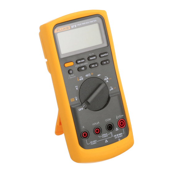
- Page 1 ® True RMS Multimeter Users Manual PN 834192 August 1988 Rev.8, 4/97 © 1988, 1989, 1990, 1992,1993, 1994, 1997 Fluke Corporation. All rights reserved. Printed in U.S.A. All product names are trademarks of their respective companies.
- Page 2 The user may find the following booklet prepared by the Federal Communications Commission helpful: How to Identify and Resolve Radio-TV Interference Problems. This booklet is available from the U.S. Govern- ment Printing Office, Washington, D.C. 20402. Stock No. 004-000-00345-4. Fluke Coporation Fluke Europe B.V. P.O. Box 9090 P.O. Box 1186 Everett, WA 98206-9090 5602 BD Eindhoven U.S.A.
-
Page 3: Table Of Contents
Table of Contents Title Page Introduction ........................1 Multimeter Safety ......................2 Getting Started Quickly ....................3 How to Use the Meter..................... 6 Input Terminals and Input Alert ................. 6 Pushbuttons....................... 8 Summary of Power-On Options................. 13 Digital and Analog Displays..................13 Holster and Flex-Stand.................... - Page 4 Users Manual Noisy Resistance Measurements................22 Measuring Capacitance .................... 22 Diode Testing......................23 Using the Analog Display..................24 Using the MIN MAX Recording Mode ............... 24 Measuring Frequency ....................26 Measuring Duty Cycle ....................27 Pulse Width Measurements ..................29 Maintenance ........................
- Page 5 List of Tables Table Title Page International Electrical Symbols..................3 Input Terminals and Limits....................4 Beeper Response in Continuity Test .................. 7 Options Available at Power-on ..................14 Approximate Charge Rate for Capacitors................. 23 Frequency Counter Operation With Current Inputs ............27 Replaceable Parts ......................
- Page 6 Users Manual...
- Page 7 List of Figures Figure Title Page Summary of Pushbutton Operation ..................9 Holster and Flex-Stand ..................... 18 Duty Cycle Measurement of Typical Logic Signal............. 28 Battery and Fuse Replacement ..................31 Replaceable Parts ......................35...
- Page 8 Users Manual...
-
Page 9: Introduction
An alternate Frequency Counter mode that measures meter. duty cycle and displays it as a value between 0.1 and The Fluke 87 True RMS Multimeter (also referred to as 99.9%. "the meter") is a handheld, 4000-count instrument that is An Input Alert that causes the beeper to sound if the designed for use in the field, laboratory, and at home. -
Page 10: Multimeter Safety
Users Manual A Touch Hold mode that allows you to keep your Avoid working alone. eyes fixed on the probes when taking measurements Do not allow the meter to be used if it is damaged, or in difficult or hazardous circumstances, then read the it's safety is impaired. -
Page 11: Getting Started Quickly
Getting Started Quickly Table 1. International Electrical Symbols Getting Started Quickly Examine the meter carefully, familiarizing yourself with the AC-Alternating See Explanation in layout of the input terminals, rotary switch, pushbuttons Current Manual and display. Notice the Warning information and summary of power-on options engraved into the rear panel. -
Page 12: Input Terminals And Limits
Users Manual Table 2. Input Terminals and Limits Input Terminals Function MIN Display MAX Display Maximum Input Reading † Reading Red Lead Black Lead 0.01 mV 1000V 1000V 0.0001V 1000V 1000V 0.01 mV 400.0 mV 1000V 0.01 40.00 M 1000V 0.001 nS 40.00 nS 1000V... - Page 13 Getting Started Quickly To operate the remaining buttons: press to select and To turn the meter on and select a function, turn the press again to exit. rotary switch from OFF to the appropriate switch position. All segments on the liquid-crystal display Note (LCD) will turn on for one second, then the meter is The response of the display and the pushbuttons...
-
Page 14: How To Use The Meter
Users Manual inserting the plug end of the test lead into the mA uA Amperes Input Terminal. input. The beeper emits an Input Alert if the fuses are For current measurements (ac or dc) up to 10A good. continuous (20A for 30 seconds) when function Although this procedure will allow you to get started selector switch is set to quickly, we suggest that you take the time to read the... -
Page 15: Beeper Response In Continuity Test
How to Use the Meter In Manual Ranging mode, 40 nS conductance range (equal to a 25-100,000 M range) is selectable. (See Power to the meter is turned off. item 9.) Volts ac Autoranges to the 05.00 nF, .0500 F, 0.500 F, or 05.00 F capacitance range. -
Page 16: Pushbuttons
Users Manual Milliamps or amperes Display Back-Light Press the YELLOW button to turn on the back-light. Defaults to dc. Press BLUE button to toggle between Back-light turns off automatically after 68 seconds to dc and ac. extend battery life. Autoranges to the 40 mA or 400 mA range when Power-On Option: 4½-Digit Display Mode using the mA A input terminal, or to the 4000 mA or The meter displays the readings at 10 times the... - Page 17 How to Use the Meter _Press to Select _Press again to Scroll or increment _Press and Hold Down for 2 Seconds to Exit MIN MAX RANGE HOLD PEAK MIN MAX _Press to Select Fequency _Press again to Select Duty Cycle _Press to Select _Press again to Exit _Press again to Exit...
- Page 18 Users Manual through the maximum (MAX), minimum (MIN), Power-On Option: Disable Automatic Power-off average (AVG), and present readings. The MIN, MAX, or AVG annunciator turns on to indicate what Automatic Power-off extends the life of the battery by value is being displayed. If an overload is recorded, turning part of the meter off if neither the rotary switch the averaging function is stopped and the average nor a pushbutton is operated for half an hour.
- Page 19 How to Use the Meter again to return to the maximum (MAX) reading. To more than 1 second duration are recorded. The "1 s" reset the Peak MIN MAX mode press Ttwice: annunciator is turned on. In the Frequency Counter the first press exits the mode, and the second press mode, readings are always recorded at the high re-enters the mode.
- Page 20 Users Manual In the MIN MAX Recording mode, press Ito Power-On Option: Rotary Switch Test stop the recording of readings; press Iagain to The Rotary Switch Test is used only for servicing resume recording. (Previously recorded readings are purposes. See the 80 Series Service Manual for not erased.) details.
-
Page 21: Summary Of Power-On Options
How to Use the Meter Relative Readings five ranges: 199.99 Hz, 1999.9 Hz, 19.999 kHz, 199.99 kHz, and greater than 200 kHz. The RANGE Press Cto enter the Relative mode, zero the button manually selects the voltage or current input display, and store the displayed reading as a range. -
Page 22: Options Available At Power-On
Users Manual Table 4. Options Available at Power-on Option Pushbutton Function Automatic Power-off Blue Disable Automatic Power-off 4½ Digit Mode Yellow Select 4½ digit display. Full scale 19,999 counts. MIN MAX Record Speed MIN MAX Select High Accuracy record speed. (Response time approximately 1 second) Rotary Switch Test Range... - Page 23 How to Use the Meter For increased sensitivity, the analog pointer moves 4000 Input Range Annunciator across the scale four times for each range. The pointer returns to 0 (wraps around) when the Displays 4, 40, 400, or 4,000 input range for volts, equivalent digital display reaches 1024, 2048, and amps, or ohms, and 400 mV.
- Page 24 Users Manual Low Battery Input changes of 100 milliseconds or longer will be recorded. In the 1 s High Accuracy MIN MAX Meter is powered by a single 9V battery, with a typical Recording Mode, the recording speed is 1 second. life of 400 hours with an alkaline battery.
-
Page 25: Holster And Flex-Stand
Applications Minimum Value in MIN MAX Recording Nanosiemens (1 x 10 siemens). Conductance Mode (1/ ) Percent Annunciator (for duty cycle readings The value displayed is the minimum reading taken only) since the MIN MAX Recording mode was entered. Ohms. Resistance Kilohm (1 x 10 ohms). - Page 26 F 1A 600V MIN INTERRUPT RATING 10 000A F 15A 600V MIN INTERRUPT RATING 10 000A 9V NEDA 1604 6F 22 006P JOHN FLUKE MFG. CO., INC. EVERETT, WA MADE IN U.S.A. PATENTS PENDING FLUKE AND PHILLIPS THE T & M ALLIANCE...
-
Page 27: Measuring Voltage (Ac/Dc)
Applications Measuring Current Measuring Voltage (AC/DC) Warning To measure voltage, connect the meter in parallel with the load or circuit under test. Each of the five ac/dc voltage Do not attempt an in-circuit current ranges presents an input impedance of approximately 10 measurement where the potential to earth is in parallel with less than 100 pF. -
Page 28: Continuity Testing
Users Manual To calculate the burden voltage: in A, multiply the display Measuring Resistance reading by 0.03V; in mA, multiply the display reading by Caution 1.8 mV; in A, multiply the display reading by 100 V. For Turn off power on the test circuit and example, at a 20 mA display reading, the burden voltage discharge all capacitors before attempting in- is 20.00 x 1.8 mV = 36 mV. -
Page 29: Using Conductance For High Resistance Or Leakage Tests
Applications When measuring resistance, be sure that the contact Using Conductance for High Resistance or between the probes and the circuit under test is good. Leakage Tests Dirt, oil, solder flux, or other foreign matter seriously Conductance is the inverse of resistance (i.e., 1/ohms) affects resistance. -
Page 30: Noisy Resistance Measurements
1 second per range. When making repeated Noisy Resistance Measurements measurements of similar values, press Kto manually Your Fluke meter is designed to tolerate up to several select the proper range and to speed up subsequent volts of ac noise. Noise appears as changing numbers on measurements. -
Page 31: Diode Testing
Applications environments, use short test leads or a test fixture (1 nF = Diode Testing 1000 pF). To perform a diode or transistor junction test: plug the test The measurement accuracy of capacitors less than 5 nF leads into the VJL and COM inputs, turn the rotary switch to L and connect the test leads across the can be improved by first using the Relative mode to zero the display and automatically subtract the residual meter... -
Page 32: Using The Analog Display
Users Manual Use the Touch Hold mode (see item 10) to make audible the analog display require practice. You will usually be diode tests. When the test leads are placed across the looking for good or bad signal patterns that occur over diode, a good diode or transistor junction will cause the some span of time. - Page 33 Applications intermittent failures. This mode follows the update time of the meter). When you display the average, the reading the analog display. (The minimum and maximum rate slows somewhat in order to calculate the average of excursions of the analog display get recorded.) the accumulated readings.
-
Page 34: Measuring Frequency
Users Manual Measuring Frequency (For example, electronic motor controls distort both voltage and current waveforms.) Select a higher input In the Frequency Counter mode, the frequency display range if you suspect multiple triggering. An alternative is autoranges to one of five ranges: 199.99 Hz, 1999.9 Hz, to turn the rotary switch to F or l, which will shift the 19.999 kHz, 199.99 kHz, and greater that 200 kHz. -
Page 35: Measuring Duty Cycle
Applications For sine waves, use the most sensitive range you can Table 6. Frequency Counter Operation With Current Inputs without getting double triggering. (Normally, a clean signal can be up to ten times the amplitude of the range you are Approximate Trigger on.) Duty cycle measurements can also be used as an Approximate... - Page 36 Users Manual +Slope -Slope Trigger Point Trigger Point 30% +Slope 70% -Slope 100% ep3f.eps Figure 3. Duty Cycle Measurement of Typical Logic Signal The precision and resolution of the duty cycle will alternate between incorrect readings. If this occurs, and the frequency reading was stable, press Mto measurements are achieved by averaging many repetitions of the input signal.
-
Page 37: Pulse Width Measurements
Maintenance Maintenance Dwell (degrees) x No. of Cylinders x 100 % Duty Cycle = 360 degrees Repairs or servicing not covered in this manual should To make a dwell measurement, set the rotary switch to F, only be performed by qualified personnel as described in select the 40V range, press Ftwice (the % the 80 Series Service Manual (refer to Table 7 for part annunciator on the right side of the LCD should turn on),... -
Page 38: Calibration
Users Manual Using a Phillips-head screwdriver, remove the three Calibration screws from the case bottom and turn the case over. Calibrate your meter once a year to ensure that it performs according to its specifications. Contact the Lift the input terminal end of the case top until it nearest Service Center or refer to the 80 Series Service gently unsnaps from the case bottom at the end Manual for calibration procedures. - Page 39 Maintenance Fuse (F2) F11A, 1000 VAC/DC Minimum Interrupt Rating 17 000A Fuse (F1) F44/100A, 1000 VAC/DC Minimum Interrupt Rating 10 000A Case Top Snaps 9V Battery Case Bottom Battery Battery Connector Case Top Case Bottom "A" "B" ep4f.eps Figure 4. Battery and Fuse Replacement...
-
Page 40: Fuse Replacement W
Referring to Figure 4, use the following procedure to postage paid, to the nearest Service Center. Include a examine or replace the meter’s fuses: description of the malfunction. Fluke assumes NO responsibility for damage in transit. -
Page 41: Replaceable Parts
Replaceable Parts A meter under warranty will be promptly repaired or Replaceable Parts replaced (at Fluke’s option) and returned at no charge. See the registration card for warranty terms. If the Note warranty has lapsed, the meter will be repaired and When servicing the meter, use only the returned for a fixed fee. -
Page 42: Replaceable Parts
TL75** Test Lead Set C81Y** Holster, Yellow C81G** Holster, Gray (Optional) C25** Carrying Case, Soft (Optional) To ensure safety, use exact replacement only. ** Items marked with two asterisks are Fluke accessories and are available from you authorized Fluke distributor. - Page 43 Replaceable Parts C81Y,C81G TL75 ep5f.eps Figure 5. Replaceable Parts...
-
Page 44: Specifications
*** Below 10% of range, add 6 digits. † The Fluke 87 is a True-RMS responding meter. The meter will display a reading (typically <25 digits) when the input leads are shorted together in the AC functions which is caused by internal amplifier noise. The accuracy on the Fluke 87 is not significantly affected by this internal offset when measuring inputs that are within 5% to 100% of the selected range. - Page 45 Specifications Specifications (cont) Function Range Resolution Accuracy* 4.000V 0.001V (0.1% + 1) 40.00 V 0.01 V (0.1% + 1) 400.0 V 0.1 V (0.1% + 1) 1000 V (0.1% + 1) 400.0 mV 0.1 mV (0.1% + 1) 400.0 (0.2% + 2)** 4.000 k 0.001 k (0.2% + 1)
- Page 46 Users Manual Specifications (cont) Function Range Resolution Accuracy*** Capacitance 5.00 nF 0.01 nF (1% + 3) 0.0500 F 0.0001 F (1% + 3) 0.500 F 0.001 F (1% + 3) 5.00 F 0.01 F (1.9% + 3) Diode Test 3.000V 0.001V (2% + 1) Function...
- Page 47 Specifications Specifications (cont) Function Range Resolution Accuracy Burden Voltage (typical) 400.0 A 0.1 A (1.0% + 2) 100 V/ A † 4000 A (1.0% + 2) 100 V/ A (45 Hz to 2 kHz) 400.0 A 0.1 A (0.2% + 3) 100 V/ A 4000 A (0.2% + 2)
- Page 48 Users Manual Specifications (cont) Frequency Counter Sensitivity and Trigger Level Input Range Minimum Sensitivity (RMS Sinewave) (Maximum input for Approximate Trigger Level 5 Hz - 20 kHz 0.5 Hz - 200 kHz specified accuracy = (DC Voltage Function) 10X Range or 1000V) 400 mV dc 70 mV (to 400 Hz) 70 mV (to 400 Hz)
- Page 49 Specifications Specifications (cont) Input Overload Common Mode Rejection Function Normal Mode Rejection Impedance Protection† Ratio (1 k unbalance) (nominal) 1000V rms 10 M <100 pF >120 dB at dc, 50 Hz or 60 Hz >60 dB at 50 Hz or 60 Hz 1000V rms 10 M <100 pF >120 dB at dc, 50 Hz or 60 Hz...
- Page 50 Users Manual Specifications (cont) Nominal Response Accuracy 100 ms to 80% Specified accuracy 12 digits for changes >200 ms in duration. (DC Functions) MIN MAX Recording 120 ms to 80% Specified accuracy 40 digits for changes >350 ms and inputs >25% (AC Functions) of range.
- Page 51 Specifications Specifications (cont) Display Digital: 4000 counts updates 4/sec 19,999 counts (4½-digit mode), updates 1/sec Analog: 4 x 32 segments (equivalent to 128), updates 40/sec Frequency: 19,999 counts, updates 3/sec @ >10 Hz Backlight: On for 68 seconds when selected. Operating Temperature -20°C to 55°C Storage Temperature...
- Page 52 Users Manual...