Table of Contents
Advertisement
Introduction
To prevent electric shock or injury, do not perform the
performance tests or calibration adjustment procedures unless
qualified to do so.
The information provided in this document is for the use of
qualified personnel only.
This document provides adjustment and performance test procedures for the
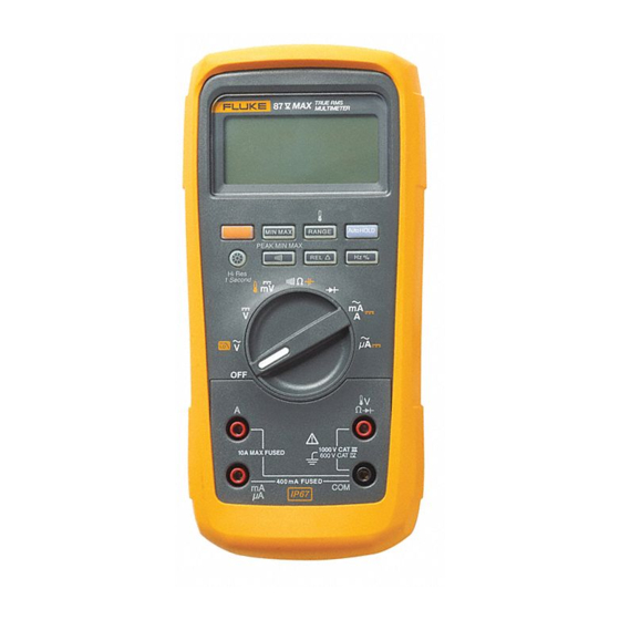
Fluke 87V MAX Digital Multimeter (the Meter).
See the 87V MAX Users Manual for complete operating instructions.
Contact Information
To contact Fluke, call one of the following telephone numbers:
•
Technical Support USA: 1-800-44-FLUKE (1-800-443-5853)
•
Calibration/Repair USA: 1-888-99-FLUKE (1-888-993-5853)
•
Canada: 1-800-36-FLUKE (1-800-363-5853)
•
Europe: +31 402-675-200
•
Japan: +81-3-6714-3114
•
Singapore: +65-6799-5566
•
China: +86-400-921-0835
•
Brazil: +55-11-3530-8901
•
Anywhere in the world: +1-425-446-5500
Or, visit Fluke's website at www.fluke.com.
To register your product, visit http://register.fluke.com.
To view, print, or download the latest manual supplement, visit
http://us.fluke.com/usen/support/manuals.
Safety Information
General Safety Information is in the printed Safety Information document that
ships with the Product and at www.fluke.com. More specific safety information is
listed where applicable.
January 2020
© 2020 Fluke Corporation. All rights reserved. Specifications are subject to change without notice.
All product names are trademarks of their respective companies.
XWWarning
87V MAX
Digital Multimeter
Calibration Information
1
Advertisement
Table of Contents

Related Manuals for Fluke 87V MAX


Summary of Contents for Fluke 87V MAX
- Page 1 Product and at www.fluke.com. More specific safety information is listed where applicable. January 2020 © 2020 Fluke Corporation. All rights reserved. Specifications are subject to change without notice. All product names are trademarks of their respective companies.
-
Page 2: General Specifications
87V MAX Calibration Information General Specifications Maximum voltage between any terminal and earth ground ........... 1000 V rms Fuse Protection for mA or μA inputs ......0.44 A, 1000V, IR 10kA Fuse Protection for A inputs........11 A, 1000 V, IR 17 kA Display Digital ................ -
Page 3: Detailed Specifications
Digital Multimeter Detailed Specifications Battery Type ..............3 AA Alkaline batteries, NEDA 15A IEC LR6 Battery Life ..............800 hr typical without backlight (Alkaline) Vibration ................ Per MIL-PRF-28800 for a Class 2 instrument Size (H x W x L) ............. 1.8 in x 3.7 in x 7.7 in (4.6 cm x 9.4 cm x 19.7 cm) Size with Holster ............ - Page 4 87V MAX Calibration Information Temperature Range Resolution [1,2] Accuracy -200 °C to +1090 °C 0.1 °C ±(1.0 % + 10) -328 °F to +1994 °F 0.1 °F ±(1.0 % + 18) [1] Does not include error of the thermocouple probe.
-
Page 5: Frequency Counter Sensitivity And Trigger Levels
Digital Multimeter Detailed Specifications Frequency Range Resolution Accuracy 199.99 Hz 0.01 Hz 1999.9 Hz 0.1 Hz ±(0.005 % + 1) 19.999 kHz 0.001 kHz 199.99 kHz 0.01 kHz >200 kHz 0.1 kHz Unspecified From 0.5 Hz to 200 kHz and for pulse widths >2 μs. Frequency Counter Sensitivity and Trigger Levels Minimum Sensitivity (RMS Sine Wave) Approximate Trigger Level... -
Page 6: Min Max Recording
87V MAX Calibration Information MIN MAX Recording Nominal Response Accuracy 100 ms to 80 % Specified accuracy ±12 counts for changes >200 ms in duration (dc functions) 120 ms to 80 % Specified accuracy ±40 counts for changes >350 ms and inputs >25 % of range (ac functions) Specified accuracy ±100 counts for changes >250 μs in duration... - Page 7 Digital Multimeter Basic Maintenance h Static Awareness h Semiconductors and integrated circuits can be damaged by electrostatic discharge during handling. This notice explains how to minimize damage to these components. 1. Understand the problem. 2. Learn the guidelines for proper handling. 3.
-
Page 8: How To Replace The Batteries
87V MAX Calibration Information Fuse Test As shown in Figure 1, with the Meter in the function, insert a test lead into the jack and place the probe tip on the other end of the test lead against the metal of the current input jack. - Page 9 Digital Multimeter Basic Maintenance Replace the battery as follows, refer to Figure 2: 1. Turn the rotary switch to OFF and remove the test leads from the terminals. 2. Remove the six Phillips-head screws from the case bottom and remove the battery door ().
- Page 10 87V MAX Calibration Information 7. Replace the fuse compartment door by aligning the arrow on the fuse door with the arrow on the case bottom and lowering the door into the fuse compartment. 8. Replace the fuse compartment seal by aligning the tab on the seal with the outline on the case bottom.
-
Page 11: Performance Tests
Digital Multimeter Performance Tests Performance Tests XWWarning To prevent electric shock, do not perform the performance test procedures unless the Meter is fully assembled. The following performance tests verify the complete operation of the Meter and check the accuracy of each Meter function against its specifications. Performance tests should be performed bi-annually to ensure that the Meter is within accuracy specifications. -
Page 12: Testing Meter Accuracy
87V MAX Calibration Information Testing Meter Accuracy To test the accuracy of the Meter, perform the steps in Table 2. Table 2. Accuracy Tests Test Step Range 5520A Output Display Reading Function 600 mV 60 mV, 60 Hz 59.2 to 60.8... - Page 13 Digital Multimeter Performance Tests Table 2. Accuracy Tests (cont.) Test Step Range 5520A Output Display Reading Function 600 mV 50 mV dc 49.8 to 50.2 600 mV 330 mV dc 329.6 to 330.4 DC Volts 600 Ω 330 Ω (Use 2 wire Comp) ...
-
Page 14: Calibration Adjustments
87V MAX Calibration Information Table 2. Accuracy Tests (cont.) Test Step Range 5520A Output Display Reading Function 0 °C mVdc -1.0 to 1.0 Temperature 100 °C 98.0 to 102.0 Backlight Press backlight button Backlight comes on Press backlight button Backlight intensifies... -
Page 15: Changing The Password
Digital Multimeter Calibration Adjustments Changing the Password To change the password in the Meter: 1. Turn the Meter Rotary Switch from OFF to VAC mode while holding down the MINMAX pushbutton at the same time. The Meter will display Y . 2. - Page 16 87V MAX Calibration Information If the revision number is 010: 4. Remove the PCB from the top case. 5. Apply power to the PCB by clipping on a dc voltage between 3.5 V and 5 V at the test points marked “+” and “-” at the edge of the board. See Figure 3.
- Page 17 Digital Multimeter Calibration Adjustments If the revision number is 011 or higher: 4. Apply power to the PCB by clipping on a dc voltage between 3.5 V and 5 V at the test points marked “+” and “-” at the edge of the board. See Figure 4. 2X-2- 3001 REV 011 3.5 - 5 V gaq102.emf...
- Page 18 87V MAX Calibration Information Other Pushbutton Functions Table 3 list the button on the Meter and describes what the button does when pressed after the password has been entered and pressed. Table 3. Pushbutton Functions During Cal Mode Button Cal Mode Description Press and hold to test the present function.
- Page 19 Digital Multimeter Calibration Adjustments Table 4. Calibration Adjustment Steps Function Adjustment Step Input Value (Switch Position) C-01 600.0 mV, 60 Hz C-02 600.0 mV, 20 kHz (AC Volts) C-03 6.000 V, 60 Hz C-04 6.000 V, 20 kHz C-05 60.00 V, 60 Hz C-06 60.00 V, 20 kHz...
-
Page 20: Disassembling The Meter
87V MAX Calibration Information Disassembling the Meter To disassemble the Meter: 1. Use a Philips screwdriver to remove the six battery-door screws (H1). 2. Lift the battery door (MP1) at the top end of the Meter and remove it from the case back. -
Page 21: Reassembling The Meter
7. Case screw o-ring: Torque case screws to 12 in-lbs torque. Verify that the o- rings are not sticking out of the sides of the screw head. Note If you want to ensure your Meter meets the IP67 rating, return the Meter to a qualified Fluke Service center. -
Page 22: Replacement Parts
87V MAX Calibration Information Replacement Parts Table 5 lists the Meter’s replaceable parts identified in Figure 5. H1 (6) MP3 (2) BT1 (3) H2 (6) H3 (6) MP8 (2) H4 (7) H4 (7) H5 (4) MP10 MP14 MP11 MP12 MP13... - Page 23 CONTACTS FLUKE-2X-II-8007, GASKET, BATT DOOR, FLUKE 27-II AVG AND 3439087 FLUKE 28-II TRMS METERS 666435 FLUKE 89-4-8012, BATTERY CONTACT, DUAL FLUKE-2X-2-2014, FUSE ACCESS DOOR, 27-2 AVG AND 28-2 TRMS 3400480 MULTIMETER 3440546 FLUKE-2X-2-2015, FUSE CAP 3320869 FLUKE-2X-2-2004, CASE, BOTTOM WITHOUT BATTERY CONTACTS...
- Page 24 Not Shown 80BK-A-8001, TYPE K THERMOCOUPLE ASSEMBLY 2747900 Not Shown FLUKE 87-5-8009, TILTSTAND 2074040 Not Shown Quick Reference Guide 5160944 Not Shown Safety Information 5160959 [1] See www.fluke.com for more information about test leads and alligator clips available for your region.
-
Page 25: Lifetime Limited Warranty
For ten years from the date of purchase, this warranty also covers the LCD. Thereafter, for the lifetime of the DMM, Fluke will replace the LCD for a fee based on then current component acquisition costs. - Page 26 87V MAX Calibration Information...