Fluke 8845A Calibration Manual
Digital multimeter
Hide thumbs
Also See for 8845A:
- Manual (126 pages) ,
- User manual (104 pages) ,
- Programmer's manual (102 pages)

Related Manuals for Fluke 8845A


Summary of Contents for Fluke 8845A
-
Page 1: Digital Multimeter
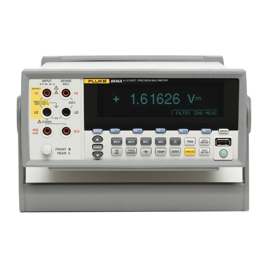
® 8845A/8846A Digital Multimeter Calibration Manual January 2007 © 2007 Fluke Corporation, All rights reserved. All product names are trademarks of their respective companies. - Page 2 Fluke authorized resellers shall extend this warranty on new and unused products to end-user customers only but have no authority to extend a greater or different warranty on behalf of Fluke. Warranty support is available only if product is purchased through a Fluke authorized sales outlet or Buyer has paid the applicable international price.
-
Page 3: Table Of Contents
Electrical......................1-10 Remote Interfaces ..................1-10 Warranty ......................1-10 Electrical Specifications ..................1-10 DC Voltage Specifications ................1-10 Input Characteristics.................. 1-10 8846A Accuracy..................1-11 8845A Accuracy..................1-11 Additional Errors..................1-11 AC Voltage Specifications ................1-11 Input Characteristics.................. 1-12 8846A Accuracy..................1-12... - Page 4 8845A/8846A Calibration Manual 8845A Accuracy..................1-13 Additional Low Frequency Errors............. 1-13 Resistance ...................... 1-14 Input Characteristics.................. 1-14 8846A Accuracy..................1-14 8845A Accuracy..................1-14 Additional Ohms Errors ................1-15 DC Current ....................1-15 Input Characteristics.................. 1-15 Accuracy (8846A)..................1-15 Accuracy (8845A)..................1-16 Additional Current Errors .................
- Page 5 Aborting a Calibration Process..............3-32 Sample Adjustment Program................. 3-32 List of Replaceable Parts..............4-1 Introduction......................4-3 How to Obtain Parts................... 4-3 How to Contact Fluke ..................4-3 Parts ........................4-4 Appendices A Verification Forms ..................A-1 B Example Adjustment Program ..............B-1...
- Page 6 8845A/8846A Calibration Manual...
- Page 7 3-10. 8845A 2-Wire Ohms Verification Steps ..............3-15 3-11. 8846A Rear-Panel Terminal Verification Steps (Optional Test) ......3-18 3-12. 8845A Rear-Panel Terminal Verification Steps (Optional Test) ......3-18 3-13. 8846A Capacitance Verification Steps ..............3-18 3-14. 8846A DC Current Verification Steps ..............3-19 3-15.
- Page 8 8845A/8846A Calibration Manual...
- Page 9 List of Figures Figure Title Page 1-1. IEC 61010 Measurement Category (CAT) Levels..........1-6 2-1. Line Fuse Replacement ..................2-5 2-2. Current Input Fuse Replacement................2-6 3-1. DC Volts Test Equipment Setup with 5520A ............3-6 3-2. AC Volts Test Equipment Setup with 5520A ............3-8 3-3.
- Page 10 8845A/8846A Calibration Manual viii...
-
Page 11: Introduction And Specifications
Chapter 1 Introduction and Specifications Title Page Introduction......................1-3 Safety Information ..................... 1-3 Symbols ......................1-4 General Safety Summary................1-4 Description of IEC 61010 Measurement Categories ......... 1-6 Organization of the Calibration Manual ............1-7 Chapter 1 – Introduction and Specifications ..........1-7 Chapter 2 –... - Page 12 8845A/8846A Calibration Manual Diode Test ..................... 1-21 Measurement Rates ..................1-21 Measurement Uncertainty.................. 1-21 Interpreting Accuracy Specifications..............1-22 24-Hour Accuracy ..................1-22 90-Day and 1-Year Accuracy ................ 1-22 Temperature Coefficients ................1-22 Configuring for Highest Accuracy Measurements ..........1-22 DC Voltage, DC Current, and Resistance Measurements ......1-22 AC Voltage and AC Current Measurements: ..........
-
Page 13: Introduction
There are a few additional features in the 8846A that are not present in the 8845A. These features will be identified with the annotation of “8846A Only” by each feature that is found only in that model. -
Page 14: Symbols
Static awareness. Static discharge Do not dispose of this product as unsorted can damage part(s) municipal waste. Contact Fluke or a qualified recycler for disposal General Safety Summary This instrument has been designed and tested in accordance with the European standard publication EN 61010-1:2001 and U.S. - Page 15 Introduction and Specifications Safety Information Table 1-2. Safety Information XW Warning To avoid possible electric shock, personal injury, or death, read the following before using the Meter: • Use the Meter only as specified in this manual, or the protection provided by the Meter might be impaired.
-
Page 16: Description Of Iec 61010 Measurement Categories
8845A/8846A Calibration Manual WCaution To prevent damage to the Meter, do not change the position of the Front/Rear switch while signals are applied to either the front or rear input terminals. Description of IEC 61010 Measurement Categories The IEC 61010 safety standard defines four Overvoltage (Installation) Categories (CAT I to CAT IV) based on the magnitude of danger from transient impulses as shown in Figure 1-1. -
Page 17: Organization Of The Calibration Manual
This calibration manual is divided into the following chapters: Chapter 1 – Introduction and Specifications This chapter introduces the Fluke 8845A and 8846A Digital Multimeters, describing their features, and accessories. This chapter also discusses use of the Calibration Manual and the various conventions used in describing the meter’s circuitry and presents a complete... - Page 18 FlukeView Forms Software Upgrade - NO cable FVF-SC4 Flukeview Forms W/Cable For 8845/8846 FVF-SC5 Flukeview Forms -Basic For 8845/8846 Y8846S Rack Mount Kit 8845A & 8846A Single Y8846D Rack Mount Kit 8845A & 8846A Dual FUSE Fuse,11A,1000V,Fast.406inx1.5in,Bulk FUSE Fuse,.440 mA,1000V,Fast,.406X1.375,Bulk...
-
Page 19: General Specifications
Introduction and Specifications General Specifications General Specifications Power Voltage 100 V Setting ............90 V to 110 V 120 V Setting ............108 V to 132 V 220 V Setting ............198 V to 242 V 240 V Setting ............216 V to 264 V Frequency ............... -
Page 20: Memory
Input Protection ............ 1000 V all ranges Overrange .............. 20 % on all ranges except 1000 V dc, 1000 V ac (8846A), 750 V ac (8845A), Diode, and 10 A ranges Remote Interfaces RS-232 (RS-232 to USB cable available to connect the Meter to a PC USB port. See Accessories) IEEE 488.2... -
Page 21: 8846A Accuracy
0.1 % of range, and for 50 to 100 kHz, add 0.13 % of range. Maximum Input............750 V rms or 1000 V peak (8845A), 1000 V rms or 1414 V peak (8846A) or 8 x 10 volts-Hertz product (whichever is less) for any range. -
Page 22: Input Characteristics
8845A/8846A Calibration Manual Input Characteristics Resolution Range Resolution Input Impedance 4½ Digits 5½ Digits 6½ Digits 100 mV 100.0000 mV 10 µV 1 µV 100 nV 1.000000 V 100 µV 10 µV 1 µV 1 MΩ ±2 % shunted 10 V 10.00000 V... -
Page 23: 8845A Accuracy
Introduction and Specifications Electrical Specifications 8845A Accuracy Accuracy is given as ± (% measurement + % of range) Temperature Frequency 24 Hour 90 Days 1 Year Coefficient/ °C Range (23 ±1 °C) (23 ±5 °C) (23 ±5 °C) (Hz) Outside 18 to 28 °C 100 mV 3 –... -
Page 24: Resistance
0.8 + 0.01 0.15 + 0.0002 1 GΩ 1.0 + 0.01 1.5 + 0.01 2.0 + 0.01 0.6 + 0.0002 8845A Accuracy Accuracy is given as ± (% measurement + % of range) Temperature 24 Hour 90 Days 1 Year Coefficient/ °C Range (23 ±1 °C) -
Page 25: Additional Ohms Errors
Introduction and Specifications Electrical Specifications Additional Ohms Errors Digits NPLC Additional Noise Error 6½ 0 % of range 6½ 0 % of range 5½ 0.001 % of range 0.001 % of range ±20 mΩ 5½ 0.01 % of range ±20 mΩ 4½... -
Page 26: Accuracy (8845A)
8845A/8846A Calibration Manual Accuracy (8845A) Accuracy is given as ± (% measurement + % of range) Temperature 24 Hour 90 Days 1 Year Coefficient/ °C Range (23 ±1 °C) (23 ±5 °C) (23 ±5 °C) Outside 18 to 28 °C 100 µA... -
Page 27: 8846A Accuracy
Introduction and Specifications Electrical Specifications 8846A Accuracy Accuracy is given as ± (% measurement + % of range) Temperature Frequency 24 Hour 90 Days 1 Year Coefficient/ °C Range (23 ±1 °C) (23 ±5 °C) (23 ±5 °C) (Hz) Outside 18 to 28 °C 100 μA 3 –... -
Page 28: 8845A Accuracy
8845A/8846A Calibration Manual 8845A Accuracy Accuracy is given as ± (% measurement + % of range) Temperature Frequency 24 Hour 90 Days 1 Year Coefficient/ °C Range (23 ±1 °C) (23 ±5 °C) (23 ±5 °C) (Hz) Outside 18 to 28 °C 10 mA 3 –... -
Page 29: 8846A Accuracy
0.01 0.001 [1] Input >100 mV. For 10 – 100 mV, multiply percent measurement error by 10. [2] Limited to 8 X 10 volt-Hertz 8845A Accuracy Accuracy is given as ± % measurement Temperature 24 Hour 90 Days 1 Year Compensation/ °C... -
Page 30: Additional Low Frequency Errors
8845A/8846A Calibration Manual Additional Low Frequency Errors Error stated as percent of measurement for inputs >100 mV. For 10 – 100 mV, multiply percent by 10. Resolution Frequency 6½ 5½ 4½ 3 – 5 Hz 0.12 0.12 5 – 10 Hz 0.17... -
Page 31: Diode Test
0.008 + 0.002 0.01 + 0.002 0.001 + 0.002 Measurement Rates Integration Time Measurements/Second Function Digits Setting 60 Hz (50 Hz) 8845A 8846A DC Volts, DC Current, and 6½ 100 NPLC 1.67 (2) s 0.6 (0.5) 0.6 (0.5) Resistance 6½... -
Page 32: Interpreting Accuracy Specifications
8845A/8846A Calibration Manual Interpreting Accuracy Specifications The following sections provide a clearer understanding of specifications over time and with temperature variations. Hour Accuracy The 24 hour accuracy specification indicates the Meter's relative accuracy over its full measurement range for short time intervals and within a stable environment. Short... -
Page 33: General Maintenance
Chapter 2 General Maintenance Title Page Introduction......................2-3 Warranty Repairs and Shipping Information ............. 2-3 General Maintenance Information ..............2-3 Required Equipment..................2-3 Power Requirements..................2-3 Static Safe Handling ..................2-3 Cleaning ......................2-4 Fuse Replacement ....................2-4 Line-Power Fuse.................... 2-4 Current-Input Fuses .................. - Page 34 8845A/8846A Calibration Manual...
-
Page 35: Introduction
If your meter is still under warranty, see the warranty information at the front of this manual for instructions on returning the unit. A list of Fluke telephone numbers and the website address can be found in the “How to Contact Fluke” section of Chapter 4. -
Page 36: Cleaning
8845A/8846A Calibration Manual punctured. The static problem is thus complicated in that failure may occur anywhere from two hours to six months after the initial damage. Two failure modes are associated with ESD. First, a person who has acquired a static charge can touch a component or assembly and cause a transient discharge to pass through the device. -
Page 37: Current-Input Fuses
4. Replace the selector block back into the fuse holder. XW Warning To avoid electric shock or fire, do not use makeshift fuses or short-circuit the fuse holder. Use only Fluke fuses. Table 2-1. Line Voltage to Fuse Rating Line Voltage Selection Fuse Rating Fluke Part No. - Page 38 5. Remove the defective fuse and replace with one having the appropriate rating (See table 4-1 for fuse ratings and Fluke part numbers). 6. Replace the protective cover by pushing it over the fuses while aligning the catches with the holes in the printed circuit board.
-
Page 39: If The Meter Does Not Turn On
“Fuse Replacement” section earlier in this chapter for instructions on changing the Meter’s voltage setting. 5. Verify that the power-line fuse is good. If these steps don’t solve the problem, then contact Fluke for more help. See the “Contacting Fluke” section in Chapter 4 for contact information. Display Tests To test the pixels on the front panel display, use the following steps. -
Page 40: Main Chassis Disassembly
8845A/8846A Calibration Manual 6. Remove the wedges from the front and rear input modules by rotating the top toward the chassis middle and pulling up. See Figure 4-1. 7. Remove both sets of screws holding the front panel to the chassis (8-32 pan head and 6-32 flat head undercut). -
Page 41: Performance Test And Calibration
Chapter 3 Performance Test and Calibration Title Page Introduction......................3-3 Required Equipment ..................3-3 Test Considerations.................... 3-5 Performance Tests....................3-5 Volts DC Verification..................3-5 Volts AC and Frequency Verification ............3-8 4-Wire Ohms Verification ................3-12 2-Wire Ohms Verification ................3-14 2X4 Test Lead Verification Steps .............. - Page 42 8845A/8846A Calibration Manual...
-
Page 43: Introduction
Volts dc Standard Fluke 5520A Must be characterized with 8508A 8½ digit meter Fluke 8508A Used to characterize the 5520A 4-wire short Fluke low thermal 4-wire Fluke PN 2653346 short or equivalent Alternate standard Fluke 5720A Volts ac Standard Fluke 5520A Must be characterized with 8508A 8½... - Page 44 To reduce the possibility of inducing errors with ac signals picked up by the test leads, use short, shielded twisted-pair PTFE-insulated test cables between the test equipment and the Meter. Fluke makes a 2 foot (PN 738716) and 4 foot (PN 738724) PTFE insulated test cable for this purpose.
-
Page 45: Test Considerations
Ideally, the standards used to verify and adjust the Meter should be four times more accurate than each full-scale error specification of the Meter. • User Fluke’s low thermal 4-Wire short for all voltages and ohmic shorts. See Table 3-1 for Fluke part number.. Performance Tests The following performance tests are provided to ensure that the Meter is in proper operating condition. - Page 46 8845A/8846A Calibration Manual INPUT SENSE 8846A 6-1/2 DIGIT PRECISION MULTIMETER 2W/4W +1.000002 1000 V CAT I FUSED 300V 600V CAT II FUSED BACK MEMORY INSTR DC V DC I AC I TRIG SETUP REAR FRONT RANGE FREQ MEAS TEMP ZERO...
- Page 47 1000 -999.9590 V -1000.0410 V -999.9490 V -1000.0510 V [1] 5520A must be used with 8508A to obtain suitable test uncertainty ratio. Table 3-3. 8845A DC Volts Verification Steps 90-day Test Limits 1-year Test Limits Nominal Range Input (V) High High 3.5 μV...
-
Page 48: Volts Ac And Frequency Verification
8845A/8846A Calibration Manual Volts AC and Frequency Verification Connect the Meter to the test equipment as shown in Figure 3-2 and, depending on which meter you are calibrating, apply the voltage listed in Table 3-4 or Table 3-5. Verification forms can be found in Appendix A which can be copied and used to record each meter reading. - Page 49 Performance Test and Calibration Performance Tests Table 3-4. 8846A AC Volts Verification Steps Nominal Input 90-day Test Limits 1-year Test Limits Range Ampl. Freq. High High 100.0 mV 10 Hz 0.100 100.09 mV 99.91 mV 100.1 mV 99.9 mV 100.0 mV 20 kHz 0.100 100.09 mV...
- Page 50 8845A/8846A Calibration Manual Table 3-5. 8845A AC Volts Verification Steps Nominal Input 90-day Test Limits 1-year Test Limits Range Ampl. Freq. High High 100.0 mV 10 Hz 0.100 100.09 mV 99.91 mV 100.1 mV 99.9 mV 100.0 mV 20 kHz 0.100...
- Page 51 Performance Test and Calibration Performance Tests Table 3-6. 8845A/8846A AC Volts Frequency Verification Steps Nominal Input 90-day Test Limits 1-year Test Limits Ampl. Freq. High High 10 Hz 10.00300 Hz 9.99700 Hz 10.00300 Hz 9.99700 Hz 40 Hz 40.0040 Hz 39.9960 Hz...
-
Page 52: 4-Wire Ohms Verification
8845A/8846A Calibration Manual 4-Wire Ohms Verification Connect the Meter to the test equipment as shown in Figure 3-3 and, depending on which meter you are calibrating, apply the resistance listed in Table 3-7 or Table 3-8. Verification forms can be found in Appendix A which can be copied and used to record each meter reading. - Page 53 1.000000 100 kΩ 100000 100.0090 kΩ 99991.0 10.00110 kΩ 99989.0 5520A must be used with 8508A to obtain suitable test uncertainty ratio. Table 3-8. 8845A 4-Wire Ohms Verification Steps 90-day Test Limits 1-year Test Limits Nominal Range Input High High 0 Ω...
-
Page 54: 2-Wire Ohms Verification
8845A/8846A Calibration Manual 2-Wire Ohms Verification Connect the Meter to the test equipment as shown in Figure 3-4 and, depending on which meter you are calibrating, apply the resistance listed in Table 3-9 or Table 3-10. Verification forms can be found in Appendix A which can be copied and used to record each meter reading. - Page 55 1.020100 GΩ 0.979900 GΩ [1] Zero Meter before each measurement. 5520A must be used with 8508A to obtain suitable test uncertainty ratio. [3] Optional test. Table 3-10. 8845A 2-Wire Ohms Verification Steps Nominal Range 90-day Test Limits 1-year Test Limits...
-
Page 56: 2X4 Test Lead Verification Steps
8845A/8846A Calibration Manual Table 3-10. 8845A 2-Wire Ohms Verification Steps (cont.) Nominal Range 90-day Test Limits 1-year Test Limits Input High High 100.000 kΩ 100000 100.0090 kΩ 99.9910 kΩ 100.0110 kΩ 99.9890 kΩ 0 Ω 10.00000 Ω 0 Ω 10.00000 Ω... - Page 57 RS-232 TRIG I/O 100 mA WARNING: N10140 SERIAL TAG TO AVOID ELECTRIC SHOCK GROUNDING CONNECTOR FLUKE CORPORATION IN POWER CORD NO INTERNAL USER SERVICEABLE PARTS MADE IN USA www.fluke.com MUST BE CONNECTED REFER SERVICE TO QUALIFIED SERVICE PERSONNEL 5520A CALIBRATOR...
- Page 58 0.099965 A 0.100055 A 0.099945 A 100 mA 100 mA 5520A must be used with 8508A to obtain suitable test uncertainty ratio. Table 3-12. 8845A Rear-Panel Terminal Verification Steps (Optional Test) 90-day Test Limits 1-year Test Limits Nominal Range Input...
-
Page 59: Capacitance Verification Steps (8846A Only)
Performance Test and Calibration Performance Tests Capacitance Verification Steps (8846A only) Connect the Meter to the test equipment as shown in Figure 3-6, and apply the capacitance values listed in Table 3-13. Verification forms can be found in Appendix A which can be copied and used to record each meter reading. -
Page 60: Dc Current Verification Steps
8845A/8846A Calibration Manual DC Current Verification Steps Connect the Meter to the test equipment as shown in Figure 3-7 and, depending on which meter you are calibrating, apply the nominal values listed in Table 3-14 or Table 3-15. Verification forms can be found in Appendix A which can be copied and used to record each meter reading. - Page 61 Performance Test and Calibration Performance Tests Table 3-14. 8846A DC Current Verification Steps 90-day Test Limits 1-year Test Limits Nominal Range Input High High 100.0 μA 25.0 ηA -25.0 ηA 25.0 ηA -25.0 ηA 100.0 μA 100.0 μA 100.065 μA 99.935 μA 100.075 μA 99.935 μA...
- Page 62 8845A/8846A Calibration Manual Table 3-15. 8845A DC Current Verifications Steps 90-day Test Limits 1-year Test Limits Nominal Range Input High High 100.0 μA 25.0 ηA -25.0 ηA 25.0 ηA -25.0 ηA 100.0 μA 100.0 μA 100.065 μA 99.935 μA 100.075 μA 99.935 μA...
-
Page 63: Ac Current Verification Steps
Performance Test and Calibration Performance Tests AC Current Verification Steps Connect the Meter to the test equipment as shown in Figure 3-8 and, depending on which meter you are calibrating, apply the nominal values listed in Table 3-16 or Table 3-17. Verification forms can be found in Appendix A which can be copied and used to record each meter reading. - Page 64 8845A/8846A Calibration Manual Table 3-16. 8846A AC Current Verification Steps Nominal Output 90-day Test Limits 1-year Test Limits Range Amplitude Freq. High High 100.0 μA 100.0 μA 100.14 μA 99.86 μA 100.14 μA 99.86 μA 10 Hz 100.0 μA 100.0 μA 100.14 μA...
-
Page 65: Adjustment (Calibration)
Performance Test and Calibration Adjustment (Calibration) Table 3-17. 8845A AC Current Verification Steps Nominal Output 90-day Test Limits 1-year Test Limits Range Ampl Freq High High 10.0 mA 10 Hz 10.0 mA 10.014 mA 9.986 mA 10.014 mA 9.986 mA 10.0 mA... -
Page 66: Unlocking The Meter For Front-Panel Adjustments (Calibration)
Changing the Calibration Password The calibration password can be changed only through the remote interface. Find the CALIBRATION:SECURE:CODE command in the “Supported SCPI Commands” section of the 8846A/8845A Programmers Manual for information on changing the calibration password. Resetting the Calibration Password If the calibration password has is lost or forgotten, the password can be reset to FLUKE884X by performing the following actions. -
Page 67: Equipment For Calibration
The required equipment for calibration is that same the equipment listed in Table 3-1. Adjustment Process The adjustment steps differ slightly between the 8845A and 8846A. In both cases, they are divided into four areas: open adjust, zero adjust, rear panel zero adjust, and gain adjust. - Page 68 8845A/8846A Calibration Manual Table 3-18. 8845A/8846A Adjustment Steps Step Modes Value Range Input Signal Description Series Open OHM 100M open ORES 100000000 open terminals OHM 1G open terminals ORES 1000000000 open (8846A only) CAP 1 nF open ZCAP 1.00E-09 open...
- Page 69 Performance Test and Calibration Adjustment (Calibration) Table 3-18. 8845A/8846A Adjustment Steps (cont) Step Modes Value Range Input Signal Description Series 4W 10 OHM (8846A ZRES 4-wire low-thermal short only) Rear Ω Zero ZRES 100000 4-wire low-thermal short 4W 100 kOHM rear input...
- Page 70 8845A/8846A Calibration Manual Table 3-18. 8845A/8846A Adjustment Steps (cont) Step Modes Value Range Input Signal Description Series ZIACS 10 A to Lo short AC 1 A ZIAC 10 A to Lo short AC 10 A ZIACS 10 A to Lo short...
- Page 71 Performance Test and Calibration Adjustment (Calibration) Table 3-18. 8845A/8846A Adjustment Steps (cont) Step Modes Value Range Input Signal Description Series GVDC DC 10 V GVDC DC 10 V GVDC DC 1 V GVDC DC 1 V GVDC DC 100 mV GVDC -0.1...
- Page 72 8845A/8846A Calibration Manual Table 3-18. 8845A/8846A Adjustment Steps (cont) Step Modes Value Range Input Signal Description Series GIDC 10.0E-3 10.0E-3 DC 10 mA GIDC -10.0E-3 -10.0E-3 DC 10 mA GIDC 100.0E-3 100.0E-3 DC 100 mA GIDC -100.0E-3 -100.0E-3 DC 100 mA Ω...
-
Page 73: Aborting A Calibration Process
PRINT @<address of meter>, "CAL? ON" INPUT LINE @<address of meter>, A$ # Disable Calibration PRINT @<address of meter>, "CAL:SEC:STAT ON, FLUKE884X” For more information about writing a program to remotely control the Meter, refer to the 8845A/8846A Programmer’s Manual. 3-33... - Page 74 8845A/8846A Calibration Manual 3-34...
-
Page 75: List Of Replaceable Parts
Chapter 4 List of Replaceable Parts Title Page Introduction......................4-3 How to Obtain Parts................... 4-3 How to Contact Fluke ..................4-3 Parts ........................4-4... - Page 76 8845A/8846A Calibration Manual...
-
Page 77: Introduction
Introduction Introduction This chapter contains an illustrated list of replaceable parts for the Fluke 8845A and 8846A Digital Multimeters. Parts are listed by assembly and alphabetized by reference designator. Each assembly is accompanied by an illustration showing the location of each part and its reference designator. -
Page 78: Parts
Singapore: +65-738-5655 Anywhere in the world: +1-425-446-5500 Visit Fluke's web site at www.fluke.com. Parts Table 4-1 lists the replaceable parts for the 8845A and 8846A Digital Multimeters. Figure 4-1 identifies the parts within the Meter. Table 4-1. Replaceable Parts Ref. - Page 79 2526849 MP22 FLUKE 27-2002,COVER, FUSE 665031 MP23 8845A-2027,HANDLE CAP, PLASTIC PART 2663315 8846A-8001,KEYPAD 2454042 8845a-8001,KEYPAD 2439221 8845A-2013,SWITCHBODY 2440417 8845A-4201,FRONT / REAR SWITCH ASSEMBLY 2571214 TRANSFORMER,POWER,100/120/220/240V,50/60HZ,31:7:1:1:7,14W,8845 A-6501,EI100,BULK 2455793 2620A-4403,WIRE ASSY,GROUND 874099 8845A-4402,WIRE ASSY 2584378 CD-ROM, PROGRAMMER AND USERS MANUAL, 8845A/8846A 2453193...
- Page 80 8845A/8846A Calibration Manual Table 4-1. Replaceable Parts (cont) Ref. Description Part Desig. Number LC1 LINE CORD,NORTH AM,10A,5-15/IEC,18/3,SVT,6.0 FT 284174 TEST LEAD SET,600V/1KV,PROBE-R/A PLUG,BLACK/RED 802980...
- Page 81 List of Replaceable Parts Parts 884XA Final Assembly (1 of 3) caw0301f.emf Figure 4-1. Final Assembly...
- Page 82 8845A/8846A Calibration Manual 884XA Final Assembly (2 of 3) caw0302f.emf Figure 4-1. Final Assembly (cont)
- Page 83 List of Replaceable Parts Parts 884XA Final Assembly (3 of 3) caw0303f.emf Figure 4-1. Final Assembly (cont)
- Page 84 8845A/8846A Calibration Manual 4-10...
-
Page 85: Appendices
Appendices Appendix Title Page Verification Forms ....................A-1 Example Adjustment Program ................B-1... - Page 86 8845A/8846A Calibration Manual...
- Page 87 Appendix A Verification Forms Introduction The following tables are forms used to collect Meter readings while performing the verification procedures contained in Chapter 3. Appendix pages may be copied as needed to record meter readings.
- Page 88 -10.000230 600.0E-6 -600.0E-6 100.0033 99.9967 -100 -99.9967 -100.0033 1000 10.0E-3 -10.0E-3 1000 1000 1000.0410 999.9590 -1000 1000 -999.9590 -1000.0410 8845A DC Volts 0.100 3.5E-6 -3.5E-6 100.0E-3 0.100 100.0075E-3 99.9925E-3 -100.0E-3 0.100 -99.9925E-3 -100.0075E-3 7.0E-6 -7.0E-6 1.000037E+0 999.963E-3 -999.963E-3 -1.000037E+0 50.0E-6 -50.0E-6...
- Page 89 Appendices Verification Forms Table A-1. Blank Verification Record for 90-Day Specifications (cont) Nominal Output Test Limits Range Results Pass/Fail Ampl. Freq. High 8845A DC Volts (cont) -100 -99.9959E+0 -100.0041E+0 1000 10.0E-3 -10.0E-3 1000 1000 1.000045E+3 999.955E+0 -1000 1000 -999.955E+0 -1.000045E+3 8845A/8846A AC Volts 100.0E-3...
- Page 90 Ampl. Freq. High 8846A Only AC Volts (cont) 20000 1000 320.460 319.540 50000 1000 320.852E+0 319.148E+0 100000 1000 322.72E+0 317.28E+0 8845A Only AC Volts 750.600 749.400 1000 750.600 749.400 10000 750.600 749.400 20000 320.385 319.615 50000 320.727E+0 319.273E+0 100000 322.52E+0 317.48E+0...
- Page 91 100000000 100000000 100810000 99190000 8846A Only 2-Wire Resistance 1000000000 100000.0 1000000000 1000000000 1015100000 984900000 8845A/8846A Optional 2X4 Test Lead (Split Lead) test 4.0E-3 100.0120 99.9880 8846A Optional Rear Panel Test 10 V 10.00023 V 9.99977 V DCV (10V) 1000 Ω...
- Page 92 8845A/8846A Calibration Manual Table A-1. Blank Verification Record for 90-Day Specifications (cont) Nominal Output Test Limits Range Results Pass/Fail Ampl. Freq. High 8846A Capacitance 1.0E-9 25.0E-12 1.0E-9 1.0E-9 1.045E-9 955.0E-12 10.0E-9 10.0E-9 10.15E-9 9.85E-9 100.0E-9 100.0E-9 101.5E-9 98.5E-9 1.0E-6 1.0E-6 1.015E-6...
- Page 93 Table A-1. Blank Verification Record for 90-Day Specifications (cont) Nominal Output Test Limits Range Results Pass/Fail Ampl. Freq. High 800.0E-6 -800.0E-6 10.0128E+0 9.9872E+0 -9.9872E+0 -10.0128E+0 8845A Only DC Current 100.0E-6 25.0E-9 -25.0E-9 100.0E-6 100.0E-6 100.065E-6 99.935E-6 -100.0E-6 100.0E-6 -99.935E-6 -100.065E-6 1.0E-3 50.0E-9 -50.0E-9 1.0E-3...
- Page 94 Nominal Output Test Limits Range Results Pass/Fail Ampl. Freq. High 1.0E-3 5000 1.0E-3 1.0014E-3 998.6E-6 1.0E-3 10000 1.0E-3 1.0045E-3 995.5E-6 8845A/8846A Current 10.0E-3 10.0E-3 10.014E-3 9.986E-3 10.0E-3 1000 10.0E-3 10.014E-3 9.986E-3 10.0E-3 5000 10.0E-3 10.014E-3 9.986E-3 10.0E-3 10000 10.0E-3 10.045E-3 9.955E-3...
- Page 95 -10.000290 600.0E-6 -600.0E-6 100.0044 99.9956 -100 -99.9956 -100.0044 1000 10.0E-3 -10.0E-3 1000 1000 1000.0510 999.9490 -1000 1000 -999.9490 -1000.0510 8845A DC Volts 0.100 3.5E-6 -3.5E-6 100.0E-3 0.100 100.0085E-3 99.9915E-3 -100.0E-3 0.100 -99.9915E-3 -100.0085E-3 7.0E-6 -7.0E-6 1.000047E+0 999.953E-3 -999.953E-3 -1.000047E+0 50.0E-6 -50.0E-6...
- Page 96 8845A/8846A Calibration Manual Table A-2. Blank Verification Record for 1-Year Specifications (cont) Nominal Output Test Limits Range Results Pass/Fail Ampl. Freq. High 8845A DC Volts (cont) -100 -99.9949E+0 -100.0051E+0 1000 10.0E-3 -10.0E-3 1000 1000 1.000055E+3 999.945E+0 -1000 1000 -999.945E+0 -1.000055E+3 8845A/8846A AC Volts 100.0E-3...
- Page 97 Ampl. Freq. High 8846A Only AC Volts (cont) 20000 1000 320.492E+0 319.508E+0 50000 1000 320.884E+0 319.116E+0 100000 1000 322.72E+0 317.28E+0 8845A Only AC Volts 750.675E+0 749.325E+0 1000 750.675E+0 749.325E+0 10000 750.675E+0 749.325E+0 20000 320.417E+0 319.583E+0 50000 320.759E+0 319.241E+0 100000 322.52E+0 317.48E+0...
- Page 98 100000000 100000000 100810000 99190000 8846A Only 2-Wire Resistance 1000000000 100000.0 1000000000 1000000000 1020100000 979900000 8845A/8846A Optional 2X4 Test Lead (Split Lead) test 4.0E-3 100.01400 99.98600 8846A Optional Rear Panel Test 10 V 10.00029 V 9.99971 V DCV (10V) 1000 Ω...
- Page 99 Appendices Verification Forms Table A-2. Blank Verification Record for 1-Year Specifications (cont) Nominal Output Test Limits Range Results Pass/Fail Ampl. Freq. High 8846A Capacitance 1.0E-9 25.0E-12 1.0E-9 1.0E-9 1.045E-9 955.0E-12 10.0E-9 10.0E-9 10.15E-9 9.85E-9 100.0E-9 100.0E-9 101.5E-9 98.5E-9 1.0E-6 1.0E-6 1.015E-6 985.0E-9 10.0E-6...
- Page 100 Table A-2. Blank Verification Record for 1-Year Specifications (cont) Nominal Output Test Limits Range Results Pass/Fail Ampl. Freq. High 800.0E-6 -800.0E-6 10.0158E+0 9.9842E+0 -9.9842E+0 -10.0158E+0 8845A Only DC Current 100.0E-6 25.0E-9 -25.0E-9 100.0E-6 100.0E-6 100.075E-6 99.935E-6 -100.0E-6 100.0E-6 -99.925E-6 -100.065E-6 1.0E-3 50.0E-9 50.0E-9 1.0E-3...
- Page 101 Nominal Output Test Limits Range Results Pass/Fail Ampl. Freq. High 1.0E-3 5000 1.0E-3 1.0014E-3 998.6E-6 1.0E-3 10000 1.0E-3 1.0045E-3 995.5E-6 8845A/8846A Current 10.0E-3 10.0E-3 10.014E-3 9.986E-3 10.0E-3 1000 10.0E-3 10.014E-3 9.986E-3 10.0E-3 5000 10.0E-3 10.014E-3 9.986E-3 10.0E-3 10000 10.0E-3 10.045E-3 9.955E-3...
- Page 102 8845A/8846A Calibration Manual A-16...
- Page 103 Appendix B Example Adjustment Program Introduction Shown below is an adjustment program example for the 8845A and 8846A. ## Adjustment of opens # Open PRINT @<address of meter>, "CAL:VAL ORES,100000000" PRINT @<address of meter>, “CAL? ON” # Check that the response is “+0” indicating accepted adjustment step.
- Page 104 8845A/8846A Calibration Manual INPUT LINE @<address of meter>, A$ PRINT @<address of meter>, "CAL:VAL ZVACS,1" PRINT @<address of meter>, “CAL? ON” INPUT LINE @<address of meter>, A$ PRINT @<address of meter>, "CAL:VAL ZVAC,10" PRINT @<address of meter>, “CAL? ON” INPUT LINE @<address of meter>, A$ PRINT @<address of meter>, "CAL:VAL ZVACS,10"...
- Page 105 Appendices Example Adjustment Program PRINT @<address of meter>, "CAL:VAL ZRES,10" PRINT @<address of meter>, “CAL? ON” INPUT LINE @<address of meter>, A$ PRINT @<address of meter>, "CAL:REC" ## REAR CAL POINTS PRINT @<address of meter>, "CAL:VAL ZRES,100000" PRINT @<address of meter>, “CAL? ON” INPUT LINE @<address of meter>, A$ PRINT @<address of meter>, "CAL:VAL ZRES,10000"...
- Page 106 8845A/8846A Calibration Manual PRINT @<address of meter>, "CAL:VAL ZIACS,10.0E-3" PRINT @<address of meter>, “CAL? ON” INPUT LINE @<address of meter>, A$ PRINT @<address of meter>, "CAL:VAL ZIAC,100.0E-3" PRINT @<address of meter>, “CAL? ON” INPUT LINE @<address of meter>, A$ PRINT @<address of meter>, "CAL:VAL ZIACS,100.0E-3"...
- Page 107 Appendices Example Adjustment Program # 100 mV AC Gain PRINT @<address of meter>, "CAL:VAL GVACS,0.1" PRINT @<address of meter>, “CAL? ON” INPUT LINE @<address of meter>, A$ ### Calibrate 100 mV AC Pole @1200 Hz # 100 mV AC Pole PRINT @<address of meter>, "CAL:VAL ACPOLE,0.1"...
- Page 108 8845A/8846A Calibration Manual # 100 V AC Pole PRINT @<address of meter>, "CAL:VAL ACPOLE,100" PRINT @<address of meter>, “CAL? ON” INPUT LINE @<address of meter>, A$ ### Calibrate 1000 V AC Gain @1200 Hz # 1000 V AC Gain PRINT @<address of meter>, "CAL:VAL GVAC,750"...
- Page 109 Appendices Example Adjustment Program ### Calibrate -1 V DC # -1V DC PRINT @<address of meter>, "CAL:VAL GVDC,-1" PRINT @<address of meter>, “CAL? ON” INPUT LINE @<address of meter>, A$ ### Calibrate 0.1 V DC # 0.1V DC PRINT @<address of meter>, "CAL:VAL GVDC,0.1" PRINT @<address of meter>, “CAL? ON”...
- Page 110 8845A/8846A Calibration Manual PRINT @<address of meter>, “CAL? ON” INPUT LINE @<address of meter>, A$ ### Calibrate 0.1 A AC @1200 Hz # 0.1 A AC PRINT @<address of meter>, "CAL:VAL GIAC,100.0E-3" PRINT @<address of meter>, “CAL? ON” INPUT LINE @<address of meter>, A$ ### Calibrate 0.1 A AC @1200 Hz...
- Page 111 Appendices Example Adjustment Program PRINT @<address of meter>, "CAL:VAL GIDC,1.0E-3" PRINT @<address of meter>, “CAL? ON” INPUT LINE @<address of meter>, A$ ### Calibrate -0.001 ADC # -0.001 ADC PRINT @<address of meter>, "CAL:VAL GIDC,-1.0E-3" PRINT @<address of meter>, “CAL? ON” INPUT LINE @<address of meter>, A$ ### Calibrate 0.01 ADC # 0.01 ADC...
- Page 112 8845A/8846A Calibration Manual # 1 kOhm PRINT @<address of meter>, "CAL:VAL GRES,1000" PRINT @<address of meter>, “CAL? ON” INPUT LINE @<address of meter>, A$ ### Calibrate 100 Ohm # 100 Ohm PRINT @<address of meter>, "CAL:VAL GRES,100" PRINT @<address of meter>, “CAL? ON”...