3Com 4500 Getting Started Manual
Switch 4500 family 26/50-port
Hide thumbs
Also See for 4500:
- Manual (942 pages) ,
- Configuration manual (742 pages) ,
- Getting started manual (134 pages)

Related Manuals for 3Com 4500


Summary of Contents for 3Com 4500
-
Page 1: Getting Started Guide
® 3Com Switch 4500 Family Getting Started Guide Switch 4500 26-Port Switch 4500 50-Port Switch 4500 PWR 26-Port Switch 4500 PWR 50-Port www.3Com.com Part No. 10012034, Rev. AC Published: March 2008... - Page 2 LICENSE.TXT or !LICENSE.TXT. If you are unable to locate a copy, please contact 3Com and a copy will be provided to you.
-
Page 3: Table Of Contents
Switch 4500 — Rear View Detail Default Settings NSTALLING THE WITCH Package Contents Important Steps Before Proceeding Connecting a Redundant Power Supply to your Switch 4500 PWR The Power-up Sequence SFP Operation Packing and Shipping the Switch 4500 ANAGING Methods of Managing a Switch... - Page 4 Access Software Downloads Telephone Technical Support and Repair Contact Us ETWORK 3Com Network Supervisor 3Com Network Director 3Com Network Access Manager 3Com Enterprise Management Suite Integration Kit with HP OpenView Network Node Manager EDUNDANT OWER Important Safety Information L’information de Sécurité Importante...
- Page 5 Importanti Informazioni di Sicurezza Wa¿ne informacje o zabezpieczeniach Regulatory Notices ECHNICAL PECIFICATIONS Switch 4500 (26 Port) Switch 4500 (50 Port) Switch 4500 PWR (26 Port) Switch 4500 PWR (50 Port) Earthing Lead REATING A TACK How To Interconnect Units Guidelines For Interconnecting Units...
-
Page 7: About This Guide
If the information in the Release Notes differ from the information in this guide, follow the instructions in the Release Notes. The latest versions of user guides and release notes are available in Adobe Acrobat Reader Portable Document Format (PDF) on the 3Com World Wide Web site: http://www.3com.com/... -
Page 8: Conventions
■ a summary of the command line interface commands for the ■ Switch. This guide is also available under the Help button on the web interface. Switch 4500 Command Reference Guide This guide provides detailed information about the web interface and... - Page 9 Switch 4500 Family Getting Started Guide Page 21 We can only respond to comments and questions about 3Com product documentation at this e-mail address. Please direct all questions related to technical support or sales in the first instance to your network supplier.
- Page 10 BOUT UIDE...
-
Page 11: Introducing The Switch 4500 Family
NTRODUCING THE WITCH This chapter contains introductory information about the Switch 4500 and how it can be used in your network. It covers summaries of hardware and software features and also the following topics: About the Switch 4500 ■ Switch 4500 — Front View Detail ■... -
Page 12: About The Switch 4500
1: I HAPTER NTRODUCING THE About the Switch 4500 The Switch 4500 Family are mixed media devices. Table 2 summarizes what each Switch consists of: Table 2 Switch 4500 Family Hardware Table 0-1 Switch 4500 Family Switch 4500 26 Port... -
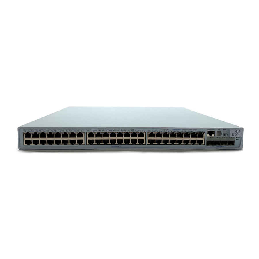
Page 13: Switch 4500 - Front View Detail
Summary of Hardware Table 3 summarizes the hardware features that are supported by the Switch 4500. Features Table 3 Hardware Features Table 0-2 Feature Addresses Auto-negotiation Forwarding Modes Duplex Modes Auto MDI/MDIX Flow Control Traffic Prioritization Power over Ethernet Ethernet and Fast Ethernet... - Page 14 Either shielded or unshielded data cables with shielded or unshielded jacks can be connected to these data sockets. 10BASE-T/ 100BASE-TX The Switch 4500 has 24 or 48 auto-negotiating 10BASE-T/100BASE-TX ports Ports configured as Auto MDIX (cross-over). These ports automatically provide the appropriate connection.
- Page 15 On the Switch 4500 10/100 26 Port unit, there are two SFP slots and two 1000Base-T ports. On the Switch 4500 PWR 26 Port, 50 Port, and PWR 50 Port models all the physical Gigabit ports are SFP slots.
- Page 16 1: I 4500 F HAPTER NTRODUCING THE WITCH AMILY will need to connect an RJ-45 to DB9 converter cable to a standard null modem cable in order to connect a terminal.
- Page 17 Unit LED The Unit LED is a seven segment display visible on the front of the Switch. The Unit LED can be used to indicate the unit number in a fabric, POST test ID and software upgrade information. In the unlikely event of a hardware fault occurring, the Unit LED may be used to help diagnose the problem.
-
Page 18: Switch 4500 - Rear View Detail
Duplex (3CR17571-91 and 3CR17572-91 only) Switch 4500 — Rear Figure 5 Switch 4500 — rear view View Detail Power Socket 100-240V; 50/60Hz; 1A Figure 6 Switch 4500 PWR - rear view Power Socket NULL 100-240V; 50/60Hz; 7.0A -53 -55V;19.5A Redundant Power System Socket... -
Page 19: Default Settings
Anhang A dieses Handbuchs aufgeführten Sicherheitshinweise lesen. ADVERTENCIA: Antes de instalar o extraer cualquier componente del Switch 4500 Family o de realizar tareas de mantenimiento, debe leer la información de seguridad facilitada en el Apéndice A de esta guía. AVVERTENZA: Prima di installare o rimuovere qualsiasi componente dello Switch 4500 Family o di eseguire qualsiasi procedura di manutenzione, leggere le informazioni di sicurezza riportate nell'Appendice A di questa guida. - Page 20 Rapid Spanning Tree Protocol Enabled Fast Start RMON Alarm Traffic Prioritization Port Security Configuration Save and Restore 4500 F AMILY Switch 4500 Filtering enabled Enabled on front panel ports Enabled All ports prioritize NBX VoIP traffic (LAN and IP). All ports set to “best effort” for all other traffic.
-
Page 21: Installing The Switch
■ ■ ■ ■ ■ ■ ■ ■ Important Steps Before proceeding, make sure to access the Switch 4500 information on 3Com’s Before Proceeding Web site at www.3Com.com and: ■ ■ ■ ■ NSTALLING THE Switch unit Unit Information Labels... -
Page 22: Connecting A Redundant Power Supply To Your Switch 4500 Pwr
NSTALLING THE WITCH Connecting a The Switch 4500 PWR 26 and 50 port have a -48V DC Redundant Power Supply Redundant Power socket that can be used in addition to the standard AC connection of the switch. Supply to your Switch If you intend to use this DC connection, please read this section. - Page 23 WARNING: Any RPS must be approved as a SELV output in accordance with IEC 60950-1/UL 60950-1/EN 60950-1. WARNING: The characteristics of the Switch 4500 DC supply input are given in Appendix E “Technical Specifications” on page 79. The Switch 4500 PWR units can be powered in three different ways: AC Mains only —...
- Page 24 AC mains and RPS AC mains and RPS RPS only AC mains Specifying the 3Com’s redundant power solution allows the use of any off-the-shelf -48V DC RPS Redundant Power that meets the requirements defined in Appendix E “Technical Specifications” System on page 79.
- Page 25 The -48V DC power distribution provides the mechanism to connect to the Switch 4500 PWR. The distribution consists of a number of circuit breakers and connection terminals for the positive (common) and negative -48V outputs. Each Switch 4500 PWR must be individually connected to a circuit breaker terminal.
- Page 26 The recommended cable length should not exceed 3 metres (9.84 feet). RPS LED The RPS status LED on the front of the Switch 4500 PWR indicates the status of the RPS and AC supplies as shown in Table 13. Table 13 RPS LED Colors...
- Page 27 Using Power over The Switch 4500 Power over Ethernet (PoE) units can supply power to any IEEE Ethernet 802.3af compliant device through any of its 10/100 ports over a Category 5 or Category 5e Ethernet cable. The same cable connects the device to the network.
-
Page 28: The Power-Up Sequence
2: I HAPTER NSTALLING THE WITCH The Power-up The following sections describe how to get your Switch 4500 powered-up and Sequence ready for operation. Powering-up the Switch Use the following sequence of steps to power-up the Switch. 4500 1 Plug the power cord into the power socket at the rear of the Switch. - Page 29 Choosing the Correct The 1000BASE-SX SFP transceiver supports a direct connection to a multi-mode Cables for the fiber-optic cable. The 1000BASE-LX SFP transceiver supports a direct connection to 1000BASE-X SFP Ports single-mode and multi-mode fiber-optic cables. The 1000BASE-LH70 SFP transceiver supports a direct connection to a single-mode fiber-optic cable and the 1000BASE-T SFP transceiver uses Category 5 copper cabling with RJ-45 connectors and supports segment lengths of up to 100 m (328 ft).
-
Page 30: Sfp Operation
■ The 3CSFP93-4500 is approved for use in the Switch 4500 only. To access the latest list of approved SFP transceivers for the Switch on the 3Com Corporation World Wide Web site, enter this URL into your internet browser: http://www.3com.com/transceiver... -
Page 31: Packing And Shipping The Switch 4500
3 Pull the wire release lever toward you to release the catch mechanism; the transceiver will then easily slide out. Packing and Shipping This section describes how to correctly package your Switch 4500 should you need the Switch 4500 to return the Switch to 3Com. - Page 32 2: I HAPTER NSTALLING THE WITCH Polystyrene Supports Cable Packaging Back Front Panel Side Panel Side of Unit of Unit 3Com Switch Unit...
-
Page 33: Managing Your Switch
To make full use of the features offered by your switch, and to change and monitor the way it works, you have to access the management software that resides on the switch. Managing the switch can help you to improve its efficiency and therefore the overall performance of your network. -
Page 34: Methods Of Managing A Switch
The prompt for system view is [4500]. Command Line Interface The Switch 4500 supports Secure Shell version 2.0 (SSHv2.0), allowing secure Management using SSH access to the switch’s Command Line Interface. If you use SSH to administer your switch and the network traffic is intercepted, no passwords or configuration information is visible in the data. -
Page 35: Setting Up Your Switch
You can manage a switch using any network management workstation running the Simple Network Management Protocol (SNMP) as shown in Figure 13. For example, you can use the 3Com Network Director software, available from the 3Com website. Figure 13 SNMP Management over the Network Refer to “Setting Up SNMP Management”... - Page 36 Switch is always allocated the same IP information.) For most installations, 3Com recommends that you assign a known IP address to your switch. This makes management simpler and more reliable as it is not Power Up the Switch.
- Page 37 Automatically Configured IP Information” section on page 38. Automatically Configuring the IP Address using DHCP By default the switch attempts to obtain an IP address from a DHCP server on the network without requesting user intervention. When using automatic IP configuration, it is important that the switch’s IP address is static so that you know...
-
Page 38: Viewing Automatically Configured Ip Information
If the login prompt does not begin immediately, press Return a few times until it starts. 3 At the login and password prompts, enter Return at the password prompt. If you have logged on correctly, <4500> is displayed as shown in Figure 15. Figure 15 User View Login ********************************************************* *no decompiling or reverse-engineering shall be allowed.*... -
Page 39: Manually Configuring Ip Information
4 Enter display ip interface br to view a summary of allocated IP addresses. The initial set up of your switch is now complete and and you can now set up a management method. See “Methods of Managing a Switch” on page 34 for details. - Page 40 ANAGING WITCH Connecting to the To set up your switch manually you can make a connection to the console port, Console Port (this example describes a local connection to the console port, rather than one using a modem). You can do this while the switch is offline (before you connect the switch to a network) or while the switch is online (connected to a network).
- Page 41 If the login prompt does not begin immediately, press Return a few times until it starts. 2 At the login prompts, enter admin password prompt press Return again. If you have logged on correctly, <4500> appears as shown below. Once you have logged in you are automatically in User View. *********************************************************** Switch 4500 9-Port BOOTROM, Version 4.01...
- Page 42 0.0.0.0 0.0.0.0 xxx.xxx.xxx.xxx (where xxx.xxx.xxx.xxx is the IP address of the default gateway) 7 From the User View, type save to save the switch’s configuration (this information is not saved automatically when the switch is powered down). You can now set up your chosen management method. See “Methods of Managing a Switch”...
-
Page 43: Setting Up The Switch With Ip Information
Using the Web Interface 1 Power-up the switch. This takes approximately one minute. 2 Open a suitable Web browser and enter the IP address of your switch in the Address field. If there is no response, wait for one minute then re-enter the IP address. -
Page 44: Setting Up Command Line Interface Management
If the login prompt does not begin immediately, press Return a few times until it starts. 3 At the login prompt, enter admin as your user name and press Return at the password prompt. If you have logged on correctly, <4500> is displayed as shown below. ****************************************************************************... -
Page 45: Setting Up Command Line Interface Management Using Ssh
If you get an error message, check that your IP information was entered correctly and the switch is powered up. 4 To open a Telnet session using the DOS prompt, enter the IP address of the switch that you wish to manage in the following format: >telnet xxx.xxx.xxx.xxx... -
Page 46: Setting Up Web Interface Management
If you get an error message, check that your IP information was entered correctly and the switch is powered up. 3 Open your web browser and enter the IP address of the switch that you wish to manage in the URL locator, for example, in the following format: http://xxx.xxx.xxx.xxx... -
Page 47: Setting Up Snmp Management
VLAN. By default, the management VLAN is 1, and all ports on the switch are in VLAN 1. For a description of 3Com’s network management applications, see Appendix C, “3Com Network Management” on page 63. - Page 48 Use the admin default user name (no password) to login and carry out initial switch setup. To set a password for the admin user in the CLI, enter the following from system view: [4500]local-user admin <cr> [4500-luser-admin]password simple xxxxxxxx (where xxxxxxxx is your chosen password). Save the configuration in the User View.
- Page 50 3: M HAPTER ANAGING WITCH...
-
Page 51: Problem Solving
■ If you experience a problem that is not listed here, it may be included in the Support section of the Switch 4500 Command Reference Guide available on 3Com’s Web site at www.3com.com. For Technical Support information, see Appendix B. -
Page 52: Solving Problems Indicated By Leds
‘problem’ device then contact your supplier for advice. The Switch and the device at the other end of the link (or cable) are connected securely. The devices at both ends of the link are powered-up The quality of cable is satisfactory Auto-negotiation settings are the same at both ends. -
Page 53: Solving Hardware Problems
Fan failure could potentially reduce the lifetime of the Switch. The monitoring system polls the fan status at periodic intervals while the unit is powered up. If one fan has failed in the Switch, a warning message will be generated in the following ways: ■... - Page 54 The Switch has identified that the SFP does not meet the minimum requirements for the Switch and has disabled the port. To correct this problem, completely remove the SFP and replace it with a 3Com approved SFP. See “Approved SFP Transceivers” on page 30.
-
Page 55: Solving Communication Problems
‘in house’ only. A device is connected to a Switch 4500 PWR but power is not being supplied If power is not being supplied to a device connected to a Switch 4500 PWR, you should do the following checks: ■... - Page 56 4: P HAPTER ROBLEM OLVING The 4500 PWR will only supply power through the front panel port to 802.3af compliant devices. Check that power budget for the Switch has not been exceeded. ■ If the power budget has been exceeded, then by default, the powered device connected to the Power over Ethernet port with the lowest priority port will lose power.
-
Page 57: Solving Stack Formation Problems
Solving Stack If you are having problems with correctly forming a stack, first ensure that Formation Problems Spanning Tree is enabled. If it is enabled, do the following: 1 Power off all units in the stack. 2 Check all the cable connections in the stack. 3 Check the ports have been enabled as stack ports. - Page 58 4: P HAPTER ROBLEM OLVING...
-
Page 59: In Outs
Null Modem Cable RJ-45 to RS-232 25-pin PC-AT Serial Cable RJ-45 to 9-pin Modem Cable RJ-45 to RS-232 25-pin OUTS Switch 4500 Cable connector: RJ-45 female Screen Shell Ground Switch 4500 Cable connector: RJ-45 female Screen Shell Ground PC/Terminal Cable connector: 25-pin male/female... -
Page 60: Ethernet Port Rj-45 Pin Assignments
10/100 and 1000BASE-T RJ-45 connections. Pin Assignments Table 10 Pin assignments Pin Number Ports configured as MDI Table 11 Pin assignments Pin Number Ports configured as MDIX Switch 4500 Cable connector: RJ-45 female Screen Shell Ground 10/100 Transmit Data + Transmit Data –... -
Page 61: Upport For Your
Expert assessment and implementation services are offered to fill resource gaps and ensure the success of your networking projects. More information on 3Com maintenance and Professional Services is available at Contact your authorized 3Com reseller or 3Com for a complete list of the value-added services available in your area. BTAINING... -
Page 62: Troubleshoot Online
■ ■ To send a product directly to 3Com for repair, you must first obtain a return authorization number (RMA). Products sent to 3Com, without authorization numbers clearly marked on the outside of the package, will be returned to the sender unopened, at the sender’s expense. - Page 63 Pakistan +61 2 9937 5083 You can also obtain support in this region using the following e-mail: apr_technical_support@3com.com Or request a repair authorization number (RMA) by fax using this number: Europe, Middle East, and Africa Telephone Technical Support and Repair...
- Page 64 UPPORT FOR YOUR Country Telephone Number You can also obtain support in this region using the following: Spanish speakers, enter the URL: http://lat.3com.com/lat/support/form.html Portuguese speakers, enter the URL: http://lat.3com.com/br/support/form.html English speakers in Latin America should send e-mail to: lat_support_anc@3com.com US and Canada Telephone Technical Support and Repair...
-
Page 65: Om Network Management
It can also offer optimization suggestions, making this application ideal for network managers with all levels of experience. To find out more about 3Com Network Supervisor and to download a trial version, go to: ETWORK 3Com Network Supervisor... -
Page 66: 3Com Network Director
By using 3ND you can discover, map, and monitor all your 3Com devices on the network. It simplifies tasks such as backup and restore for 3Com device configurations as well as firmware and agent upgrades. -
Page 67: 3Com Enterprise Management Suite
The client-server offering operates on Windows and UNIX (Linux and Solaris) systems. 3Com EMS is available in four packages, varying in the maximum number of devices actively managed. These include SNMP-capable devices such as switches, routers, security switches, the 3Com VCX™ IP Telephony server, and wireless access points: ■... - Page 68 C: 3C PPENDIX ETWORK ANAGEMENT...
-
Page 69: Supply Safety Information
WARNING: These instructions must be read in conjunction with the RPS flyer and the safety and installation instructions supplied with your RPS. WARNING: When powering any Switch 4500 from an RPS, the unit must be earthed (grounded). This can be achieved by either connecting the power cord to the unit or by connecting the earth terminal on the rear of the unit to a reliable electrical earth, or by connecting both. -
Page 70: L'information De Sécurité Importante
à la terre, conformément à la norme IEC 60950-1/UL 60950-1/EN 60950-1. AVERTISSEMENT: Ces instructions doivent être lues conjointement avec les caractéristiques de l'alimentation CC du Switch 4500 fournies en annexe C, Spécifications techniques. AVERTISSEMENT: Vous devez respecter les recommandations du... -
Page 71: Wichtige Sicherheitsinformationen
VORSICHT: Diese Anleitungen müssen im Zusammenhang mit den Sicherheitshinweisen und Installationsanleitungen zu Ihrer RPS gelesen werden. VORSICHT: Bei der Stromversorgung eines Switch 4500 über eine RPS muss das Gerät geerdet sein. Hierfür kann entweder das Netzkabel an das Gerät angeschlossen werden oder die Erdungsklemme an der Rückseite des Geräts mit einer zuverlässigen elektrischen Erdung... -
Page 72: Información De Seguridad Importante
Klemme am Switch an die negative (gemeinsame) Klemme der RPS angeschlossen wird. VORSICHT: Stellen Sie sicher, dass sich der Schutzschalter an der RPS beim Anschließen des RPS-Kabels und des Steckers des 3Com Switch in der geöffneten Stellung (Aus) befindet. VORSICHT: Verwenden Sie mit den 3Com PoE-Netzwerkswitches kein "positiv geerdetes"... - Page 73 SELV sin toma de tierra según IEC 60950-1/UL 60950-1/EN 60950-1. ADVERTENCIA: Estas instrucciones deben leerse junto con las características de la entrada de suministro de CC del Switch 4500 del Apéndice C, Especificaciones técnicas. ADVERTENCIA: al conectar el cable al RPS deberán seguirse las recomendaciones del fabricante.
-
Page 74: Importanti Informazioni Di Sicurezza
AVVERTENZA: queste istruzioni devono essere lette insieme alle istruzioni di sicurezza e installazione fornite con l'RPS. AVVERTENZA: se si accende uno Switch 4500 da un RPS, l'unità deve disporre di messa a terra. Per accendere lo switch, è possibile collegare il cavo di alimentazione all'unità, collegare il terminale di terra situato sul... -
Page 75: Wa¿Ne Informacje O Zabezpieczeniach
OSTRZEŻENIE: Te instrukcje należy przeczytać razem z instrukcjami dotyczącymi bezpieczeństwa i instalacji dostarczonymi z systemem zasi- lania nadmiarowego. OSTRZEŻENIE: Jeśli dowolny przełącznik Switch 4500 jest zasilany z zasilacza RPS, urządzenie musi być uziemione. Można to uzyskać przez podłączenie przewodu zasilającego do urządzenia lub przez podłączenie końcówki uziemienia z tyłu urządzenia do dobrego elementu uziemi-... - Page 76 -48-woltowego nadmiarowego systemu zasilania odpowiedniego przy użyciu ze sprzętem telekomunikacyjnym wraz z przełącznikami siecio- wymi firmy 3Com w technologii Power-over-Ethernet (PoE). Aby spełnić wymagania specyfikacji IEEE 802.3af (PoE), -48-woltowy przewodnik wyjścia musi być odizolowany od ziemi (uziomu) i spełnił wymagania...
-
Page 77: Regulatory Notices
A copy of the signed Declaration of Conformity can be downloaded from the Product Support web page for the Switch 4500 Product Family at http://www.3com.com. Also available at http://support.3com.com/doc/Switch_4500_EU_DOC.pdf. - Page 78 D: R PPENDIX EDUNDANT OWER UPPLY AFETY NFORMATION...
-
Page 79: Specifications
–10 ° to +70 °C (14 ° to 158 °F) Operating Humidity 95% non-condensing Standards EN60068 to 3Com schedule (Package testing: paras 2.1, 2.2, 2.30, and 2.32. Operational testing: paras 2.1, 2.2, 2.30 and 2.13). Safety Agency Certifications UL 60950, EN60950, CSA 22.2 No. 60950, IEC 60950... -
Page 80: Switch 4500 (50 Port)
–10 ° to +70 °C (14 ° to 158 °F) Operating Humidity 95% non-condensing Standards EN60068 to 3Com schedule (Package testing: paras 2.1, 2.2, 2.30, and 2.32. Operational testing: paras 2.1, 2.2, 2.30 and 2.13). Safety Agency Certifications UL60950, EN60950, CSA 22.2 No. 60950, IEC 60950... -
Page 81: Switch 4500 Pwr (26 Port)
–10 ° to +70 °C (14 ° to 158 °F) Operating Humidity 95% non-condensing Standards EN60068 to 3Com schedule (Package testing: paras 2.1, 2.2, 2.30, and 2.32. Operational testing: paras 2.1, 2.2, 2.30 and 2.13). Safety Agency Certifications UL60950, EN60950, CSA 22.2 No. 60950, IEC 60950... -
Page 82: Switch 4500 Pwr (50 Port)
–10 ° to +70 °C (14 ° to 158 °F) Operating Humidity 95% non-condensing Standards EN60068 to 3Com schedule (Package testing: paras 2.1, 2.2, 2.30, and 2.32. Operational testing: paras 2.1, 2.2, 2.30 and 2.13). Safety Agency Certifications UL60950, EN60950, CSA 22.2 No. 60950, IEC 60950... -
Page 83: Rps
Safety Requirements The RPS shall comply with the following safety standards: EN60950, UL60950, CSA22.2 60950, IEC60950 Emissions CISPR 22 Class A, EN55022 Class A, FCC Part 15 Subpart B Class A, ICES-003 Class A, AS/NZS 3548 Class A, VCCI Class A, EN61000-3-2, EN61000-3-3 Immunity EN 55024... - Page 84 E: T PPENDIX ECHNICAL PECIFICATIONS...
-
Page 85: Creating A Stack
■ ■ How To Interconnect Up to eight 3Com Switch 4500 units can be interconnected to create a stack and Units then treated as a single manageable unit with one IP address. You can interconnect your Switches to create a stack using a standard 1000 Mbps Ethernet connection. -
Page 86: Unit Numbering Within The Stack
■ ■ Figure 18 Unit Numbering When a stack is created using the Switch 4500 the unit numbering can be within the Stack determined in two ways. ■ The maximum number of Switch units that can be interconnected is eight. - Page 87 MAC address assumes the ID in question and the other unit will automatically renumber. 3Com recommends that you manually assign the unit IDs within the stack if you wish to have predictability of knowing which units have which IDs at all times.
- Page 88 88 Appendix F: C REATING A TACK...