Table of Contents
Advertisement
Quick Links
Advertisement
Table of Contents

Related Manuals for Asus P4V533-MX


Summary of Contents for Asus P4V533-MX
- Page 1 P4V533-MX User Guide...
- Page 2 Product warranty or service will not be extended if: (1) the product is repaired, modified or altered, unless such repair, modification of alteration is authorized in writing by ASUS; or (2) the serial number of the product is defaced or missing.
-
Page 3: Table Of Contents
Notices .................... v Safety information ................vi About this guide ................vii ASUS contact information ............viii P4V533-MX specifications summary ..........ix Chapter 1: Product introduction 1.1 Welcome! ................1-2 1.2 Package contents ............... 1-2 1.3 Special features ..............1-3 1.4 Motherboard components .......... - Page 4 2.2.4 Menu items ............2-6 2.2.5 Sub-menu items ............. 2-6 2.2.6 Configuration fields ..........2-6 2.2.7 Pop-up window ............2-6 2.2.8 Scroll bar ..............2-6 2.2.9 General help ............2-6 2.3 Main menu ................2-7 2.3.1 System Time [xx:xx:xxxx] ........2-7 2.3.2 System Date [Day xx/xx/xxxx] .......
-
Page 5: Federal Communications Commission Statement
Federal Communications Commission Statement This device complies with FCC Rules Part 15. Operation is subject to the following two conditions: • This device may not cause harmful interference, and • This device must accept any interference received including interference that may cause undesired operation. This equipment has been tested and found to comply with the limits for a Class B digital device, pursuant to Part 15 of the FCC Rules. -
Page 6: Electrical Safety
Electrical safety • To prevent electrical shock hazard, disconnect the power cable from the electrical outlet before relocating the system. • When adding or removing devices to or from the system, ensure that the power cables for the devices are unplugged before the signal cables are connected. -
Page 7: Asus Contact Information
1. ASUS Websites The ASUS websites worldwide provide updated information on ASUS hardware and software products. The ASUS websites are listed in the ASUS Contact Information on page viii. 2. Optional Documentation Your product package may include optional documentation, such as warranty flyers, that may have been added by your dealer. - Page 8 Technical Support Support Fax: +1-502-933-8713 General Support: +1-502-995-0883 Notebook Support: +1-510-739-3777 x5110 Support Email: tsd@asus.com ASUS COMPUTER GmbH (Germany and Austria) Address: Harkortstr. 25, 40880 Ratingen, BRD, Germany General Email: sales@asuscom.de (for marketing requests only) General Fax: +49-2102-9599-31 Web Site: www.asuscom.de...
- Page 9 Manageability WfM 2.0, DMI 2.0, WOL/WOR by PME, SMBus Form Factor ATX form factor: 9.6 in x 8.0 in (24.5 cm x 20.5 cm) Support CD contents Device drivers ASUS PC Probe ASUS LiveUpdate Trend Micro™ PC-cillin 2002 anti-virus software...
-
Page 11: Chapter 1: Product Introduction
This chapter describes the features of the P4V533-MX motherboard. It includes brief descriptions of the motherboard components, and illustrations of the layout, jumper settings, and connectors. Product introduction... - Page 12 ® Thank you for buying the ASUS P4V533-MX motherboard! The ASUS P4V533-MX motherboard delivers a host of new features and latest technologies making it another standout in the long line of ASUS quality motherboards! ® ® The P4V533-MX incorporates the Intel...
- Page 13 Latest processor technology ® ® The P4V533-MX motherboard supports the latest Intel Pentium 4 Processor via a 478-pin surface mount ZIF socket. The Pentium 4 processor with 512KB L2 cache on 0.13 micron process includes a 533/400 MHz system bus and features the new Hyper-Threading technology and FMB2 power design that allow up to 2.8+ GHz...
- Page 14 Before you install the motherboard, learn about its major components and available features to facilitate the installation and future upgrades. Refer to the succeeding pages for the component descriptions. Chapter 1: Product introduction...
- Page 15 PS/2 mouse port. This green 6-pin connector is for a PS/2 mouse. Parallel port. This 25-pin port connects a parallel printer, a scanner, or other devices. RJ-45 port. This port allows connection to a Local Area Network (LAN) through a network hub. ASUS P4V533-MX motherboard user guide...
- Page 16 Line In jack. This Line In (light blue) jack connects a tape player or other audio sources. In 6-channel mode, the function of this jack becomes Bass/ Center. Line Out jack. This Line Out (lime) jack connects a headphone or a speaker.
-
Page 17: Pci Slot
Top:Line In Center:Line Out Below:Mic In 2Mbit AUDIO1 Flash Accelerated Graphics Port BIOS (AGP) P4V533-MX GAME1 PCI Slot 1 LED1 CHA_FAN1 PCI Slot 2 VT8235 CLRCMOS1 PCI Slot 3 AUX1 Audio Codec FLOPPY1 USB56 PANEL1 ASUS P4V533-MX motherboard user guide... - Page 18 Failure to do so may cause severe damage to the motherboard, peripherals, and/or components. ® LED1 P4V533-MX Standby Powered Power P4V533-MX Onboard LED Chapter 1: Product introduction...
-
Page 19: Motherboard Components
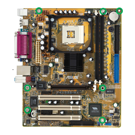
Place seven (7) screws into the holes indicated by circles to secure the motherboard to the chassis. Do not overtighten the screws! Doing so may damage the motherboard. Place this side towards the rear of the chassis ASUS P4V533-MX motherboard user guide... -
Page 20: Overview
1.8.1 Overview The motherboard comes with a surface mount 478-pin Zero Insertion Force (ZIF) ® ® socket. The socket is designed for the Intel Pentium 4 Processor in the 478-pin package with 512KB L2 cache. This processor supports 533/400MHz front side bus (FSB), and allows data transfer rates of up to 4.3GB/s. -
Page 21: Installing The Cpu
6. Install a CPU heatsink and fan following the instructions that came with the heatsink package. 7. Connect the CPU fan cable to the CPU_FAN1 connector on the motherboard. ASUS P4V533-MX motherboard user guide 1-11... -
Page 22: System Memory
104 Pins ® P4V533-MX 80 Pins P4V533-MX 184-Pin DDR DIMM Sockets 1.9.1 Installing a DIMM Make sure to unplug the power supply before adding or removing DIMMs or other system components. Failure to do so may cause severe damage to both the motherboard and the components. -
Page 23: Standard Interrupt Assignments
— shared — — — EHCI — — — — shared — — — Onboard LAN — — — — — used — — Onboard audio — — — — — — used — ASUS P4V533-MX motherboard user guide 1-13... -
Page 24: Pci Slots
This motherboard has an Accelerated Graphics Port (AGP) slot that supports AGP 4X (3.3V/1.5V) cards. Note the notches on the card golden fingers to ensure that they fit the AGP slot on your motherboard. ® P4V533-MX P4V533-MX Accelerated Graphics Port (AGP ) 1-14 Chapter 1: Product introduction... -
Page 25: Jumper
Except when clearing the RTC RAM, never remove the cap on CLRTC1 jumper default position. Removing the cap will cause system boot failure! CLRCMOS1 ® P4V533-MX Normal Clear CMOS (Default) P4V533-MX Clear RTC RAM Setting ASUS P4V533-MX motherboard user guide 1-15... - Page 26 Otherwise, the system does not power up. 2. The total current consumed must NOT exceed the power supply capability (+5VSB) whether under normal or in sleep mode. ® USBPWR56 P4V533-MX +5VSB P4V533-MX USB Device Wake Up (Default) 1-16 Chapter 1: Product introduction...
- Page 27 PIN 1 NOTE: Orient the red markings on the floppy ribbon cable to PIN 1. P4V533-MX Floppy Disk Drive Connector 2. GAME/MIDI connector (16-1 pin GAME1) This connector supports a GAME/MIDI module. Connect the GAME/MIDI cable with yellow connector to the yellow header onboard. The GAME/MIDI port on the module connects a joystick or a game pad for playing games, and MIDI devices for playing or editing audio files.
-
Page 28: Connectors
2. The hole near the blue connector on the UltraDMA133/100/66 cable is intentional. 3. For UltraDMA133/100/66 IDE devices, use the 80-conductor IDE cable. NOTE: Orient the red markings on the IDE ribbon cable to PIN 1 ® P4V533-MX PIN 1 PIN 1 P4V533-MX IDE Connectors 1-18 Chapter 1: Product introduction... - Page 29 Do not forget to connect the fan cables to the fan connectors. Lack of sufficient air flow within the system may damage the motherboard components. These are not jumpers! DO NOT place jumper caps on the fan connectors! CPU_FAN1 ® CHA_FAN1 P4V533-MX P4V533-MX 12-Volt Cooling Fan Power ASUS P4V533-MX motherboard user guide 1-19...
- Page 30 P4V533-MX Ground Right Audio Channel P4V533-MX Internal Audio Connectors 7. USB header (10-1 pin USB56) If the USB ports on the rear panel are inadequate, two USB headers are available for additional USB ports. The USB header complies with USB 2.0 specification that supports up to 480 Mbps connection speed.
- Page 31 This is an interface for the Intel front panel audio cable that allow convenient connection and control of audio devices. AUDIO1 ® MIC2 AGND MICPWR +5VA BLINE_OUT_R Line out_R P4V533-MX Line out_L BLINE_OUT_L P4V533-MX Front Panel Audio Connector ASUS P4V533-MX motherboard user guide 1-21...
-
Page 32: Important Note
P4V533-MX IDE_LED Reset SW Requires an ATX power supply. P4V533-MX Front Panel Audio Connector • System Power LED Lead (2-pin PWR LED) This 2-1 pin connector connects to the system power LED. The LED lights up when you turn on the system power, and blinks when the system is in sleep mode. -
Page 33: Chapter 2: Bios Information
This chapter tells how to change system settings through the BIOS Setup menus. Detailed descriptions of the BIOS parameters are also provided. BIOS information... -
Page 34: Creating A Bootable Floppy Disk
2.1.2 Using AFUDOS to update the BIOS Update the BIOS using the AFUDOS.EXE utility in DOS environment. 1. Visit the ASUS website (www.asus.com) to download the latest BIOS file for your motherboard. Save the BIOS file to a bootable floppy disk. - Page 35 Copyright (C) 2002 American Megatrends, Inc. All rights reserved. Reading file ..done Erasing flash ..done Writing flash ..0x0008CC00 (9%) Verifying flash .. done A:\> 5. Reboot the system from the hard disk. ASUS P4V533-MX motherboard user guide...
-
Page 36: Bios Setup Program
The BIOS setup screens shown in this chapter are for reference purposes only, and may not exactly match what you see on your screen. Visit the ASUS website (www.asus.com) to download the latest product and BIOS information. Chapter 2: BIOS information... -
Page 37: Bios Menu Screen
At the bottom right corner of a menu screen are the navigation keys for that particular menu. Use the navigation keys to select items in the menu and change the settings. Some of the navigation keys differ from one screen to another. ASUS P4V533-MX motherboard user guide... -
Page 38: Menu Items
Primary IDE Master :[ST320413A] Use [+] or [-] to Primary IDE Slave :[ASUS CD-S340] configure system time. Secondary IDE Master :[Not Detected] For example, selecting Main shows the Secondary IDE Slave... -
Page 39: System Time [Xx:xx:xxxx]
2.3.3 Legacy Diskette A, B [1.44M, 3.5 in.] Sets the type of floppy drive installed. Configuration options: [Disabled] [360K, 5.25 in.] [1.2M , 5.25 in.] [720K , 3.5 in.] [1.44M, 3.5 in.] [2.88M, 3.5 in.] ASUS P4V533-MX motherboard user guide... -
Page 40: Primary/Secondary/Third/Fourth Ide Master/Slave
2.3.4 Primary/Secondary/Third/Fourth IDE Master/Slave While entering Setup, BIOS auto-detects the presence of IDE devices. There is a separate sub-menu for each IDE device. Select a device item then press Enter to display the IDE device information. Primary IDE Master Select the type Device : Hard Disk of device connected... -
Page 41: System Information
Select Item Change Option General Help Save and Exit Exit AMI BIOS This item displays the auto-detected BIOS information. Processor This item displays the auto-detected CPU specification. System Memory This item displays the auto-detected system memory. ASUS P4V533-MX motherboard user guide... -
Page 42: Advanced Menu
The Advanced menu items allow you to change the settings for the CPU and other system devices. Take caution when changing the settings of the Advanced menu items. Incorrect field values may cause the system to malfunction. Configure CPU. CPU Configuration Chipset Onboard Devices Configuration PCI PnP... - Page 43 This item controls the latency between the SDRAM read command and the time the data actually becomes available. Configuration options: [2.0 Clocks] [2.5 Clocks] Precharge to Active (Trp) [3T] Configuration options: [2T] [3T] Active to Precharge (Tras) [6T] Configuration options: [5T] [6T] ASUS P4V533-MX motherboard user guide 2-11...
- Page 44 Active to CMD (Trcd) [3T] Configuration options: [2T] [3T] SDRAM Bank Interleave [Disabled] This item controls the latency between the SDRAM read command and the time the data actually becomes available. Configuration options: [Disabled] [2-Way] [4-Way] SDRAM Burst Length [4QW] Configuration options: [8QW] [4QW] SDRAM Command Rate [2T] Configuration options: [2T] [1T]...
-
Page 45: Onboard Devices Configuration
Allows selection of the EPP version. This item appears only when the Parallel Port Mode is set to EPP. Configuration options: [DMA0] [DMA1] [DMA3] Parallel Port IRQ [IRQ7] Allows you to select the Parallel Port IRQ. Configuration options: [IRQ5] [IRQ7] ASUS P4V533-MX motherboard user guide 2-13... - Page 46 OnBoard Game Port [Enabled] This item enable or disables the onboard Game port. Configuration options: [Disabled] [Enabled] OnBoard MIDI Port [300] This item enable or disables the onboard MIDI port. Configuration options: [Disabled] [300] [200/330] [330] MIDI IRQ Select [IRQ10] Allows you to select the MIDI Port IRQs.
-
Page 47: Pci Pnp
Configuration options: [Yes] [No] IRQ xx [Available] When set to [Available], the specific IRQ is free for use of PCI/PnP devices. When set to [Reserved], the IRQ is reserved for legacy ISA devices. Configuration options: [Available] [Reserved] ASUS P4V533-MX motherboard user guide 2-15... -
Page 48: Power Menu
The Power menu items allow you to change the settings for the Advanced Power Management (APM). Select an item then press Enter to display the configuration options. Suspend Mode [Auto] Configure CPU. Repost Video on S3 Resume [Yes] ACPI 2.0 Support [No] ACPI APIC Support [Enabled]... -
Page 49: Apm Configuration
Allows you to select the video power down mode. Configuration options: [Disabled] [Standby] [Suspend] Hard Disk Power Down Mode [Suspend] Allows you to set the hard disk power down mode. Configuration options: [Disabled] [Standby] [Suspend] ASUS P4V533-MX motherboard user guide 2-17... - Page 50 Power On Ring [Disabled] This allows either settings of [Enabled] or [Disabled] for powering up the computer when the external modem receives a call while the computer is in Soft-off mode. Configuration options: [Disabled] [Enabled] The computer cannot receive or transmit data until the computer and applications are fully running.
-
Page 51: Hardware Monitor
If any of the monitored items is out of range, the following error message appears: “Hardware Monitor found an error. Enter Power setup menu for details”. You will then be prompted to “Press F1 to continue or DEL to enter SETUP”. ASUS P4V533-MX motherboard user guide 2-19... -
Page 52: Boot Menu
Specifies the boot sequence from the 1st Boot Device [1st Floppy Drive] available devices. 2nd Boot Device [PM-ST330620A] 3rd Boot Device [SM-ASUS CD-S360] A device enclosed in parenthesis has been disabled in the corresponding type menu. Select Screen Select Item... -
Page 53: Boot Settings Configuration
Interrupt 19 Capture [Disabled] When set to Enabled, the system allows option ROMs to trap interrupt 19. This is required by some PCI cards that provide a ROM based setup utility. Configuration options: [Disabled] [Enabled] ASUS P4V533-MX motherboard user guide 2-21... -
Page 54: Security
2.6.3 Security The Security menu items allow you to change the system security settings. Select an item then press Enter to display the configuration options. Security Settings <Enter> to change password. Supervisor Password Installed <Enter> again to User Password Not Installed disable password. -
Page 55: Change User Password
Clear User Password Select this item if you wish to clear the user password. Boot Sector Virus Protection [Disabled] Allows you to enable or disable the boot sector virus protection. Configuration options: [Disabled] [Enabled] ASUS P4V533-MX motherboard user guide 2-23... -
Page 56: Exit Menu
The Exit menu items allow you to load the optimal or failsafe default values for the BIOS items, and save or discard your changes to the BIOS items. Exit Options Exit system setup after saving the Exit & Save Changes changes. -
Page 57: Software Support
This chapter describes the contents of the support CD that comes with the motherboard package. Software support... -
Page 58: Running The Support Cd
The contents of the support CD are subject to change at any time without notice. Visit the ASUS website for updates. 3.2.1 Running the support CD To begin using the support CD, simply insert the CD into your CD-ROM drive. The CD automatically displays the Drivers menu if Autorun is enabled in your computer. -
Page 59: Drivers Menu
ASUS PC Probe This smart utility monitors the fan speed, CPU temperature, and system voltages, and alerts you on any detected problems. This utility helps you keep your computer at a healthy operating condition. ASUS P4V533-MX motherboard user guide... -
Page 60: Install Asus Update
Install ASUS Update This program allows you to download the latest version of the BIOS from the ASUS website. Before using the ASUS Update, make sure that you have an Internet connection so you can connect to the ASUS website.