Table of Contents
Advertisement
Advertisement
Table of Contents

Related Manuals for Asus P4V8X-MX


Summary of Contents for Asus P4V8X-MX
- Page 1 P4V8X-MX User Guide...
- Page 2 Product warranty or service will not be extended if: (1) the product is repaired, modified or altered, unless such repair, modification of alteration is authorized in writing by ASUS; or (2) the serial number of the product is defaced or missing.
-
Page 3: Table Of Contents
Contents Notices ......................v Safety Information ..................vi About This Guide ..................vii P4V8X-MX Specifications Summary ............viii Chapter 1: Product Introduction Welcome! ..................1-2 Package Contents ................1-2 Special Features ................1-2 1.3.1 Product highlights ............1-2 1.3.2 Innovative ASUS features ..........1- Before You Proceed ............... - Page 4 Contents 2.1.4 Using ASUS EZ Flash to update the BIOS ..... 2-5 2.1.5 ASUS CrashFree BIOS 2 utility ........2-6 BIOS Setup Program ..............2-8 2.2.1 BIOS menu screen ............2-9 2.2.2 Menu bar ................. 2-9 2.2.3 Navigation keys ............... 2-9 2.2.4...
-
Page 5: Notices
Notices Federal Communications Commission Statement This device complies with FCC Rules Part 15. Operation is subject to the following two conditions: • This device may not cause harmful interference, and • This device must accept any interference received including interference that may cause undesired operation. -
Page 6: Safety Information
Safety Information Electrical safety • To prevent electrical shock hazard, disconnect the power cable from the electrical outlet before relocating the system. • When adding or removing devices to or from the system, ensure that the power cables for the devices are unplugged before the signal cables are connected. -
Page 7: About This Guide
ASUS websites The ASUS websites worldwide provide updated information on ASUS hardware and software products. Refer to the ASUS contact information. Optional documentation Your product package may include optional documentation, such as warranty flyers, that may have been added by your dealer. These documents are not... -
Page 8: P4V8X-Mx Specifications Summary
ASUS Special features ASUS EZ Flash ASUS MyLogo2 FSB frequency adjustable with 1MHz step (SFS) Overclock Features ASUS C.P.R. (CPU Parameter Recall) 1 x Parallel port Back panel I/O ports 1 x Serial (COM1) port 1 x PS/2 Keyboard port (purple) - Page 9 P4V8X-MX Specifications Summary BIOS features 4 Mb Flash ROM, AMI BIOS, PnP, DMI2.0, WfM2.0, SM BIOS 2.3, ACPI 2.0a, C.P.R. (CPU Parameter Recall), ASUS CrashFree BIOS2, ASUS EZ Flash, MyLogo2, PXE, RPL Industry standard PCI 2.2, USB 2.0/1.1 Manageability WfM 2.0, DMI 2.0, WOL by PME, WOR by PME...
-
Page 10: Chapter 1: Product Introduction
This chapter describes the motherboard features and the new technologies it supports. Product Introduction... -
Page 11: Welcome
P4V8X-MX motherboard! The motherboard delivers a host of new features and latest technologies, making it another standout in the long line of ASUS quality motherboards! Before you start installing the motherboard, and hardware devices on it, check the items in your package with the list below. -
Page 12: Innovative Asus Features
ROM (See page 2-6). ASUS EZ Flash BIOS With ASUS EZ Flash, you can update BIOS before entering operating system. No more DOS-based flash utility and bootable diskette required (See page 2-5). -
Page 13: Before You Proceed
The illustration below shows the location of the onboard LED. SB_PWR P 4 V 8 X - M X Standby Powered P4V8X-MX Onboard LED Power Chapter 1: Product Introduction... -
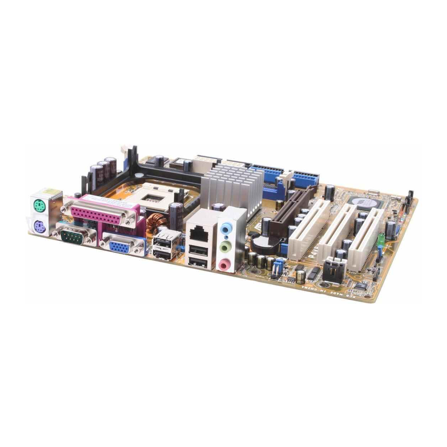
Page 14: Motherboard Overview
RJ-45 CHA_FAN USB4 Top:Line In Center:Line Out Below:Mic In CR2032 3V Lithium Cell CMOS Power FP_AUDIO PCI1 P 4 V 8 X - M X PCI2 VT8237R PLUS PCI3 CHASSIS AUDIO SPDIF_OUT SB_PWR PANEL USB78 SATA1 SATA2 ASUS P4V8X-MX Motherboard... -
Page 15: Placement Direction
1.5.2 Placement direction When installing the motherboard, make sure that you place it into the chassis in the correct orientation. The edge with external ports goes to the rear part of the chassis as indicated in the image below. 1.5.3 Screw holes Place six screws into the holes indicated by circles to secure the motherboard to the chassis. -
Page 16: Central Processing Unit (Cpu)
CPU to prevent overheating. Do not use processors with core speeds of less than 1GHz. Gold Arrow P 4 V 8 X - M X P4V8X-MX CPU Socket 478 Notes on Intel Hyper-Threading Technology This motherboard supports Intel ®... -
Page 17: Installing The Cpu
To use the Hyper-Threading Technology on this motherboard: Buy an Intel Pentium 4 CPU that supports Hyper-Threading Technology, Install the CPU Power up the system and enter BIOS Setup (see Chapter 4). Under Hyper-Threading the AAdvanced Menu, make sure that the item Technology is set to Enabled, The item appears only if you installed a CPU that supports Hyper-Threading Technology. -
Page 18: System Memory
4. For optimum compatibility, it is recommended that you obtain memory modules from qualified vendors. See the next page for a list of qualified DDR333 DIMM vendors. 5. Visit ASUS website (www.asus.com) for latest DDR333 Qualified Vendor List. ASUS P4V8X-MX Motherboard... - Page 19 Qualified Vendors List (QVL) Size Vendor Model Brand SS/DS Component 256MB Kingston KVR333X64C25/256 Kingston D3208DH1T-6 256MB Kingston KVR333X64C25/256 Hynix HY5DU56822BT-D43 512MB Kingston KVR333X64C25/512 Kingston D3208DH1T-6 512MB Kingston KVR400X64C3A/512 Hynix HY5DU56822BT-D43 512MB Kingston KVR400X64C3A/512 Kingston D3208DH1T-5 256MB Kingston KVR400X64C3A/256 Kingston D3208DL3T-5A 256MB Kingston KVR400X64C3A/256...
-
Page 20: Installing A Dimm
DIMM. Support the DIMM lightly with your fingers when pressing the retaining clips. The DIMM might get damaged when it flips out with extra force. Remove the DIMM from the socket. ASUS P4V8X-MX Motherboard 1-11... -
Page 21: Expansion Slots
Expansion slots In the future, you may need to install expansion cards. The following sub-sections describe the slots and the expansion cards that they support. Make sure to unplug the power cord before adding or removing expansion cards. Failure to do so may cause you physical injury and damage motherboard components. -
Page 22: Standard Interrupt Assignments
When using PCI cards on shared slots, ensure that the drivers support “Share IRQ” or that the cards do not need IRQ assignments; otherwise, conflicts will arise between the two PCI groups, making the system unstable and the card inoperable. ASUS P4V8X-MX Motherboard 1-13... -
Page 23: Agp Slot
fit into the AGP slot. P 4 V 8 X - M X Keyed for 1.5v P4V8X-MX Accelerated Graphics Port (AGP) 1.8.4 PCI slots The PCI slots support cards such as a LAN card, SCSI card, USB card, and other cards that comply with PCI specifications. -
Page 24: Jumpers
Except when clearing the RTC RAM, never remove the cap on CLRTC jumper default position. Removing the cap will cause system boot failure! Clear CMOS CLRTC P 4 V 8 X - M X Normal (Default) P4V8X-MX Clear RTC RAM ASUS P4V8X-MX Motherboard 1-15... - Page 25 +5VSB (Default) P 4 V 8 X - M X P4V8X-MX PS2 USB Power Setting 1. This device wake-up feature requires a power supply that can provide 500mA on the +5VSB lead for each USB, keyboard and mouse devices, otherwise, the system will not power up.
-
Page 26: Connectors
Video Graphics Adapter port. This 15-pin port is for a VGA monitor or other VGA-compatible devices. 10. Serial connector. This 9-pin COM1 port is for pointing devices or other serial devices. 11. PS/2 keyboard port (purple). This port is for a PS/2 keyboard. ASUS P4V8X-MX Motherboard 1-17... -
Page 27: Internal Connectors
PIN 1 P 4 V 8 X - M X P4V8X-MX Floppy Disk Drive Connector IDE connectors (40-1 pin PRI_IDE, SEC_IDE) This connector is for an Ultra D M A 1 3 3 s i g n a l c a b l e . T h e U l t r a... - Page 28 flow inside the system may damage the motherboard components. These are not jumpers! Do not place jumper caps on the fan connectors! CPU_FAN Rotation +12V CHA_FAN Rotation +12V P 4 V 8 X - M X P4V8X-MX CPU Fan Connectors ASUS P4V8X-MX Motherboard 1-19...
- Page 29 USB_P8- USB_P7- USB+5V USB+5V P4V8X-MX USB 2.0 Connectors Never connect a 1394 cable to the USB connectors. Doing so will damage the motherboard! Internal audio connectors (4-pin CD, AUX) These connectors allow you to receive stereo audio input from sound sources such as a CD-ROM, TV tuner, or MPEG card.
- Page 30 I/O ports. FP_AUDIO P 4 V 8 X - M X P4V8X-MX Front Panel Audio Connector ATX power connector (20-pin ATXPWR and 4-pin ATX 12V) This connectors are for the 20-pin ATX power and 4-pin ATX 12V supply plugs.
- Page 31 CHASSIS P 4 V 8 X - M X (Default) P4V8X-MX Chassis Intrusion Connectors 10. Digital audio connector (3- pin SPDIF) This connector is for the S/PDIF audio module that allows digital sound input. •...
- Page 32 IDE_LED P 4 V 8 X - M X PWRSW Requires an ATX power supply. P4V8X-MX System Panel Connector • System power LED (3-1 pin PLED) This connector is for the system power LED. Connect the chassis power LED cable to this connector. The system power LED lights up when you turn on the system power, and blinks when the system is in sleep mode.
-
Page 33: Chapter 2: Bios Setup
T h i s c h a p t e r t e l l s h o w t o c h a n g e the system settings through the BIOS Setup menus. Detailed descriptions of the BIOS parameters are also provided. BIOS Setup... -
Page 34: Managing And Updating Your Bios
(Updates the BIOS in DOS mode using a bootable floppy disk.) 2. ASUS EZ Flash (Updates the BIOS using a floppy disk during POST.) 3. ASUS CrashFree BIOS 2 - Updates the BIOS using a bootable floppy disk or the motherboard support CD. -
Page 35: Using Afudos To Update The Bios
Write the BIOS filename on a piece of paper. You need to type the exact BIOS file name at the prompt. 2. Copy the AFUDOS.EXE utility from the support CD to the bootable floppy disk that contains the BIOS file. 3. Boot the system from the floppy disk. ASUS P4V8X-MX Motherboard... - Page 36 4. At the DOS prompt, type the command line: afudos /i[filename.rom] where [filename.rom] means the latest (or original) BIOS file that you copied to the bootable floppy disk. 5. Press <Enter>. The screen displays the status of the update process. The BIOS information on the screen is for reference only.
-
Page 37: Using Asus Ez Flash To Update The Bios
To update the BIOS using ASUS EZ Flash: 1. Visit the system builder website to download the latest BIOS file for your motherboard and rename it to P4V8X-MX.ROM. Save the BIOS file to a floppy disk. 2. Reboot the system. -
Page 38: Asus Crashfree Bios 2 Utility
2.1.5 ASUS CrashFree BIOS 2 utility The ASUS CrashFree BIOS 2 is an auto recovery tool that allows you to restore the BIOS file when it fails or gets corrupted during the updating process. You can update a corrupted BIOS file using the motherboard support CD or the floppy disk that contains the updated BIOS file. - Page 39 Restart the system after the utility completes the updating process. The recovered BIOS may not be the latest BIOS version for this motherboard. Visit the ASUS website (www.asus.com) to download the latest BIOS file. ASUS P4V8X-MX Motherboard...
-
Page 40: Bios Setup Program
2.2 BIOS Setup Program The BIOS software is constantly being updated so the BIOS setup screens and descriptions in this section are for reference purposes only, and may not exactly match what you see on your screen. This motherboard supports a programmable Low Pin Count (LPC) chip that you can update using the provided utility described in section “2.1 Managing and updating your BIOS.”... -
Page 41: Bios Menu Screen
At the bottom right corner of a menu screen are the navigation keys for that particular menu. Use the navigation keys to select items in the menu and change the settings. Some of the navigation keys differ from one screen to another. ASUS P4V8X-MX Motherboard... -
Page 42: Menu Items
2.2.4 Menu items The highlighted item on the menu bar displays the specific items for that menu. For example, selecting Main shows the Main menu items. The other items (Advanced, Power, Boot, and Exit) on the menu bar have their respective menu items. -
Page 43: Main Menu
[1.2M , 5.25 in.] [720K , 3.5 in.] [1.44M, 3.5 in.] [2.88M, 3.5 in.] 2.3.4 Legacy Diskette B [Disabled] Sets the type of floppy drive installed. Configuration options: [Disabled] [360K, 5.25 in.] [1.2M , 5.25 in.] [720K , 3.5 in.] [1.44M, 3.5 in.] [2.88M, 3.5 in.] ASUS P4V8X-MX Motherboard 2-11... - Page 44 2.3.5 Primary/Secondary IDE Master/Slave, SATA1/SATA2 While entering Setup, BIOS automatically detects the presence of IDE devices. There is a separate sub-menu for each IDE device. Select a device item then press <Enter> to display the IDE device information. Primary IDE Master Select the type of device connected Device...
- Page 45 OnBoard IDE Controller [Enabled] Allows selection of the IDE operation mode depending on the operating system (OS) that you installed. Configuration options: [Disabled] [Enabled] SATA Operation Mode [RAID] Allows you to set SATA Operation Mode. Configuration options: [non-RAID] [RAID] ASUS P4V8X-MX Motherboard 2-13...
-
Page 46: System Information
2.3.7 System Information This menu gives you an overview of the general system specifications. The items in this menu are auto-detected by the BIOS. AMIBIOS Version : 08.00.12 Build Date : 08/10/05 Processor Type : Intel (R) Pentium(R) 4 CPU 2.40GHz Speed : 2400MHz Count... -
Page 47: Advanced Menu
Select Screen ←→ CPU Configuration Select Item ↑↓ CPU Host Frequency [Auto] Change Option Actual Frequency (MHz) [133] General Help Save and Exit Boot Failure Guard [Enabled] Exit Spread Spectrum [Auto] v02.58 (C)Copyright 1985-2004, American Megatrends, Inc. ASUS P4V8X-MX Motherboard 2-15... - Page 48 Max CPUID Value Limit [Disabled] Enable this item to boot legacy operating systems that cannot support CPUs with extended CPUID functions. Configuration options: [Disabled] [Enabled] CPU Internal Thermal Control [Auto] Disables or sets the CPU internal control. Configuration options: [Auto] [Disabled] CPU Host Frequency [Auto] While entering setup, BIOS auto detects the present CPU host frequency of this motherboard.
-
Page 49: Usb Configuration
USB devices at startup. If detected, the USB controller legacy mode is enabled. If no USB device is detected, the legacy USB support is disabled. Configuration options: [Disabled] [Enabled] [Auto] ASUS P4V8X-MX Motherboard 2-17... -
Page 50: Chipset
2.4.3 Chipset The Chipset menu allows you to change the advanced chipset settings. Select an item then press <Enter> to display the sub-menu. Chipset Settings Memory Clock can be set by the code using DRAM Frequency [Auto] AUTO, or you can set DRAM CAS# Latency [Auto] one of the standard... - Page 51 The default value of this feature is set to [Auto]. Configuration options: [Auto] [4X] AGP Fast Write [Disabled] Allows you to disable or enable the feature of AGP Fast Write protocol support. Configuration options: [Disabled] [Enabled] ASUS P4V8X-MX Motherboard 2-19...
- Page 52 AGP 3.0 Calibration [Auto] Configuration options: [Auto] [Disabled] [Enabled] AGP Staggered Delay [Auto] Configuration options: [Auto] [None] [Delay 1ns] AGP GADSTB Output Delay [Auto] Configuration options: [Auto] [None] [Delay 150 psec] [Delay 300 psec] [Delay 450 psec] V-Link Speed [Normal] Configuration options: [Normal] [Fast] PCI Delay Transaction [Enabled] Allows you to disable or enable the PCI Delay Transaction.
-
Page 53: Onboard Devices Configuration
[Disabled] [378] [278] Parallel Port Mode [ECP+EPP] Allows you to select the Parallel port mode. Configuration options: [Normal] [Bi- Directional] [EPP+ECP] Parallel Port IRQ [IRQ7] Allows you to select the Parallel Port IRQ. Configuration options: [IRQ5] [IRQ7 ASUS P4V8X-MX Motherboard 2-21... -
Page 54: Pcipnp
2.4.5 PCI PnP The PCI PnP menu items allow you to change the advanced settings for PCI/PnP devices. The menu includes setting IRQ and DMA channel resources for either PCI/PnP or legacy ISA devices. Take caution when changing the settings of the PCIPnP menu items. Incorrect field values can cause the system to malfunction. -
Page 55: Power Menu
Allows you to add more tables for ACPI 2.0 specifications. Configuration options: [No] [Yes] ACPI APIC Support [Enabled] Enables or disables the ACPI support in the ASIC. When set to Enabled, the ACPI APIC table pointer is included in the RSDT pointer list. Configuration options: [Disabled] [Enabled] ASUS P4V8X-MX Motherboard 2-23... -
Page 56: Apm Configuration
2.5.1 APM Configuration Set the power state Restore on AC/Power Loss [Power off] after an unexpected Ring-In Power On [Disabled] AC/Power loss. PCI Devices Power On [Disabled] PS/2 Keyboard Power On [Disabled] RTC Alarm Power On [Disabled] Select Screen ←→ Select Item ↑↓... -
Page 57: Hardware Monitor
When using this type of CPU fan, you can not reduce the CPU fan speed even if you set the CPU Q-Fan Mode to [PWM]. VCORE Voltage, 3.3V Voltage, 5V Voltage, 12V Voltage The onboard hardware monitor automatically detects the voltage output through the onboard voltage regulators. ASUS P4V8X-MX Motherboard 2-25... -
Page 58: Boot Menu
2.6 Boot menu The Boot menu items allow you to change the system boot options. Select an item then press <Enter> to display the sub-menu. Boot Settings Specifies the Boot Device Priority Boot Device Priority sequence. A virtual floppy disk Boot Settings Configuration drive (Floppy Drive B: Security... -
Page 59: Boot Device Priority
Allows you to enable or disable the full screen logo display feature. Configuration options: [Disabled] [Enabled] Set this item to [Enabled] to use the ASUS MyLogo™ feature. Boot From Network [Disabled] Allows you to enable or disable the boot from network option. Configuration... -
Page 60: Security
2.6.3 Security The Security menu items allow you to change the system security settings. Select an item then press <Enter> to display the configuration options. <Enter> to change Security Settings password. <Enter> again to Supervisor Password :Not Installed disable password. User Password :Not Installed Change Supervisor Password... -
Page 61: Exit Menu
Setup menus. When you select this option, or if you press <F5>, a confirmation window appears. Select [Yes] to load the default values. Select Exit & Save Changes or make other changes before saving the values to the non-volatile RAM. ASUS P4V8X-MX Motherboard 2-29... - Page 62 This chapter describes the contents of the support CD that comes with the motherboard package. Software Support...
-
Page 63: Installing An Operating System
The contents of the support CD are subject to change at any time without notice. Visit the ASUS website(www.asus.com) for updates. 3.2.1 Running the support CD Place the support CD to the optical drive. The CD automatically displays the Drivers menu if Autorun is enabled in your computer. -
Page 64: Drivers Menu
3.2.3 Utilities menu The Utilities menu shows the applications and other software that the motherboard supports. ASUS PC Probe ASUS PC Probe can monitor Fan Speed, Voltage, and CPU Temperature to keep your PC safe. ASUS P4V8X-MX Motherboard... -
Page 65: Manual Menu
ASUS Update ASUS Update can help user to download and flash BIOS. Please install Network Card and TCP/IP network driver first, otherwise ASUS Update can not work properly. ASUS Screen Saver Bring life to your idle screen by installing the ASUS screen saver. -
Page 66: Contacts Menu
Please install first Adobe Acrobat, then open the VIA8237 SATA Quick Setup Guide. 3.2.5 Contacts menu Click the Contact tab to display the ASUS contact information. You can also find this information on the inside front cover of this user guide. -
Page 67: Via Raid Configurations
VIA RAID configurations The motherboard includes a high performance IDE RAID controller integrated in the VIA VT8237R southbridge chipset. It supports RAID 0, RAID 1 and JBOD with two independent Serial ATA channels. RAID 0 (called Data striping) optimizes two identical hard disk drives to read and write data in parallel, interleaved stacks. - Page 68 ↑ , ↓ : Move to next item Enter : Confirm the selection : Exit Channel Drive Name Array Name Mode Size(GB) Status Serial_Ch0 Master XXXXXXXXXXX ARRAY 0 SATA 999.99 XXXXXXX Serial_Ch1 Master XXXXXXXXXXX ARRAY 0 SATA 999.99 XXXXXXX ASUS P4V8X-MX Motherboard...
-
Page 69: Raid 0 For Performance
RAID 0 for performance From the create array menu, select Array Mode, then press <Enter>. The supported RAID configurations appear on a pop-up menu. RAID 0 for performance RAID 1 for data protection RAID SPAN for capacity Select RAID 0 for performance then press <Enter>. From this point, you may choose to auto-configure the RAID array by selecting Auto Setup for Performance or manually configure the RAID array for stripped sets. -
Page 70: Raid 1 For Data Protection
If you select <N>, the following confirmation message appears. The data on the selected disks will be destroyed. Continue? (Y/N) 10. Press <Y> to confirm or <N> to return to the configuration options. 11. Press <Esc> to go back to main menu. ASUS P4V8X-MX Motherboard... -
Page 71: Creating A Raid Driver Disk
Creating a RAID driver disk ® A floppy disk with the RAID driver is required when installing Windows 2000/XP operating system on a hard disk drive that is included in a RAID set. You can create a RAID driver disk using your motherboard support CD. To create a RAID driver disk: Insert the motherboard support CD into the CD-ROM drive.