Table of Contents
Advertisement
Available languages
Available languages
Operator's
Manual
CRRFTSMRH
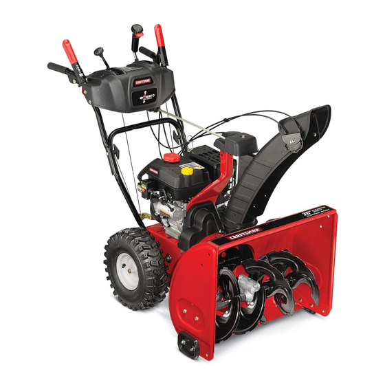
26" SNOW THROWER
Model No. 247.88970
CAUTION:
Before
using
this product,
read this
manual
and follow
all
safety
rules
and operating
instructions.
o SAFETY
ASSEMBLY
OPERATION
MAINTENANCE
PARTS LIST
o ESPANOL
Sears, Roebuck and Co., Hoffman
Estates,
IL 60179, U.S.A.
Visit our website:
www.craftsman.com
FORM1/0. 769-05136A
7/31/2009
Advertisement
Table of Contents

Related Manuals for Craftsman 88970 - 208 CC 26 in. 2 Stage Snow Thrower


Summary of Contents for Craftsman 88970 - 208 CC 26 in. 2 Stage Snow Thrower
- Page 1 SAFETY ASSEMBLY OPERATION MAINTENANCE PARTS LIST CAUTION: Before using o ESPANOL this product, read this manual and follow safety rules and operating instructions. Sears, Roebuck and Co., Hoffman Estates, IL 60179, U.S.A. Visit our website: www.craftsman.com FORM1/0. 769-05136A 7/31/2009...
- Page 2 Craftsman snow thrower fails due toadefect inmaterial orworkman- ship within t wo years from the date ofpurchase, return i ttoany Sears store, Sears Parts & Repair Service Center, orother Craftsman outlet inthe United States forfree repair (orreplacement ifrepair proves impossible).
- Page 3 This machinewas builtto be operatedaccordingto the safeopera- This symbolpointsout importantsafetyinstructionswhich,if not tion practicesin this manual.As with anytype of powerequipment, followed,couldendangerthepersonalsafetyand/orpropertyof carelessnessor error on the partof the operatorcan resultin serious yourselfand others. Readand followall instructionsin this manual injury.This machineis capableof amputatingfingers,hands,toes beforeattemptingto operatethis machine.Failureto complywith and feet and throwingdebris.Failureto observethe followingsafety these instructionsmay resultin personalinjury.Whenyou seethis...
- Page 4 Safe Handling of Gasoline • Exerciseextremecautionwhenoperatingon or crossinggravel surfaces.Stay alertfor hidden hazardsor traffic. Toavoidpersonalinjuryor propertydamageuseextremecare in handlinggasoline.Gasolineis extremelyflammableand the vaporsare • Exercisecautionwhenchangingdirectionand whileoperatingon explosive.Seriouspersonalinjurycan occurwhengasolineis spilled slopes. on yourselfor yourclotheswhichcan ignite.Washyour skin and • Planyoursnow-throwing patternto avoiddischargetowards changeclothesimmediately. windows,walls,cars etc. Thus,avoidingpossibleproperty •...
- Page 5 MAINTENANCE & STORAGE DO NOT MODIFY ENGINE • Nevertamperwith safetydevices.Checktheirproperoperation Toavoidseriousinjuryor death,do not modifyengine in any way. regularly.Referto the maintenance and adjustmentsectionsof Tampering with the governorsettingcanlead to a runawayengineand this manual. cause it to operateat unsafespeeds.Nevertamperwithfactory setting of engine governor. •...
- Page 6 SAFETY SYMBOLS This pagedepictsand describessafetysymbolsthat mayappear on this product. Read,understand,and followall instructionson the machine beforeattemptingto assembleand operate. READ THE OPERATOR'S MANUAL(S) Read, understand, and follow all instructions in the manual(s) before attempting to assemble operate WARNING-- ROTATING BLADES Keep hands out of inlet and discharge openings while machine is running.
- Page 7 100/.LIIO-NV:IIO "lVflNV_ S,UOIVU3dOQV3H"G "S3OV_IJflS ] 3AVUONO 9NIIV_J3dO N3HM NOIIflVO VSIX] qsfl"S9]ONVIS181V ]98VHOSIO 103810 83A3N 'S]IUflrNI SI03PgoNMOUHIQIOAV 01 "_ "3NIHOV_ONIOIA83S UOONIOOO]ONfl ]UO_38O3ddOIS]AVHSlHPd9NIAOW 11VlllNfl S]IQNVH ONIH]8NIVW3U ONV ']NION]dOlS'88]A]1HOlnlo]9VON]SIO "8 "]lnHg ]gHVHOSIO 9010Nfl01 1001 lflO-NP]lO ]Sfl "Z "l]]d ONV SONVH ]lPlnd_P NVO H3onv uo Hq]l]d_JIHIIM IOVINO0 "u39np ONV _J3113dWI 9NllVIOU_JOH_ I VMV d]3H "L...
- Page 8 NOTE:References to rightor left sideof the snowthrowerare determined from behindthe unit in the operatingposition(standing directlybehindthe snow thrower,facingthe handlepanel). ChuteControl Head REMOVING FROM CARTON ..f ::_Chute Support Cut the cornersof thecarton and lay the sidesflat on the ground. Bracket Removeand discard all packinginserts. Movethe snowthrowerout of thecarton.
- Page 9 Placechuteontochute baseand ensurehexrod is positioned ChuteControlf under handlepanel.Installhex boltpreviouslyremovedbut do not securewith wingnut at this time.See Figure4. Squeezethetriggeron the handlepaneljoystickand rotatethe chute byhand to face forward.The holesin the chutecontrol inputwill be facing up. See Figure5. NOTE:The chutewill not rotatewithoutsqueezing the triggeron the joystick.
- Page 10 7, Insertthe hexend of chute rod intothe inputshaftbelowjoystick on handlepanel,Make sureto line up the hole in the hexend of chute rodwith the arrowon the inputshaft.See Figure7. NOTE:The chute rodwill fit snugglyintothe inputshaft. Supportthe rear of the dashpanelwith one hand whileinsertingthe chute rodwith yourotherhand to ensurethe chute rod is insertedall the way intothe inputshaft.
- Page 11 ..ill IIIhll iillii! 10. Checkthat all cables are properlyroutedthroughthecable guide on theengine.See Figure10. NOTE: Forsmoothestoperation,the cables shouldall be to the left of the chutecontrol rod. 11. Theextensioncord forthe electricstarteris fastenedwith a cabletie to the rearof the auger housingfor shippingpurposes. Cutthe cabletie and removecord beforeoperatingthe unit.
- Page 12 Chute Clean-Out Tool A chute clean-out tool is fastenedto the top of the augerhousing with a mountingclip. See Figure12.The tool is designedto cleara chuteassemblyof ice and snow.This item is fastenedwith a cabletie at the factory.Cut thecable tie beforeoperatingthe snowthrower. Chute Clean-out Tool loft _1 .allm?vingparts have.
- Page 13 Auger Control Priorto operatingyoursnowthrower,carefullyread and followall instructionsbelow.Performall adjustments to verifyyoursnow throweris operatingsafelyand properly. Checktheadjustmentof the augercontrolas follows: Whentheauger controlis releasedand in the disengaged"up" position,the cableshouldhavevery little slack. It shouldNOTbe tight. In a well-ventilated area,start the snowthrowerengine.Refer to Startingthe Enginein the Operationsection.Makesurethe throttleis set in the FASTposition.
- Page 14 Shift Lever Drive Control z Four-WayChuteControP (Joystick) Auger Control Gas Cap Chute Assembly Mumer Recoil Starter Handle CleanOut Tool Primer FUEL LEVEL Throttle Control Choke Control Electric Starter Button Oil Drain Electric Starter Outlet Augers Skid Shoe Figure15 Nowthat youhaveset up yoursnowthrower,it's importantto become acquainted with its controlsand features.Referto Figure15.
- Page 15 THROTTLE CONTROL DRIVE CONTROL/AUGER CONTROL LOCK DRIVE CONTROL Thethrottlecontrolis locatedon the rearof the engine.It regulatesthe speedof theengine and will shutoff the enginewhenmovedintothe STOPposition. Depressingthe primerforcesfuel directlyinto the engine'scarburetorto aid in cold-weather The drivecontrolis locatedon the righthandle.Squeezethe control starting. grip againstthe handleto engagethe wheeldrive. Releaseto stop. The drivecontrolalso lockstheauger controlso youcan operate RECOIL STARTER...
- Page 16 CLEAN-OUT TOOL • Refuelin a well-ventilated area with the enginestopped.Do not smokeor allowflamesor sparksin the areawherethe engineis refueledor wheregasolineisstored. Neveruse yourhandsto cleara cloggedchute assembly.Shut • Donot overfillthe fueltank.After refueling,makesurethe tank off engineand remainbehindhandlesuntilall movingpartshave cap is closed properlyand securely. stoppedbeforeusingthe clean-outtoolto clear thechute assembly. •...
- Page 17 2. Move t hrottle control toFAST (rabbit) _ position. TO ENGAGE DRIVE I,"1 pos t /co d 3. Move c hoke tothe CHOKE engine start). If With the throttlecontrolin the Fast(rabbit) '_ position,move engineis warm,placechokein RUNposition. shiftleverintoone of thesix forward(F) positionsor two reverse Pushprimerthree (3) times, makingsureto covervent hole when (R) positions.Selecta speedappropriatefor the snowconditions pushing.If engine iswarm,push primeronlyonce.
- Page 18 MAINTENANCE SCHEDULE Beforeperforming anytypeof maintenance/service, disengage all Followthe maintenanceschedulegivenbelow.This chart describes controls and stoptheengine.Waituntilall moving partshavecometo serviceguidelinesonly. Usethe ServiceLog columnto keeptrackof a complete stop.Disconnect sparkplugwireandgrounditagainstthe completedmaintenance tasks.To locate the nearest Sears Service enginetoprevent u nintended starting. A lways wearsafety glassesduring Centeror to scheduleservice,simplycontactSears at 1-800-4-MY-HOME®.
- Page 19 Changing Engine Oil NOTE:Changethe engineoil after the first 5 hoursof operationand oncea seasonor every 50 hoursthereafter. Drainfuelfrom tank by runningengineuntilthe fuel tank is empty. Be surefuel fill cap is secure. Placesuitableoil collectioncontainerunderoil drain plug. Removeoil drain plug.See Figure18. Tip engineto drainoil intothe container.Usedoil mustbe disposedof at a propercollectioncenter.
- Page 20 Measurethe plug gap with a feelergauge.Correctas necessary by bendingsideelectrode.See Figure20. Thegap shouldbe set to .02-.03inches (0.60-0.80ram). Electrode Checkthat thespark plug washeris in good conditionand thread the sparkplug in by handto preventcross-threading. Afterthe sparkplug is seated,tightenwith a spark plugwrenchto compressthe washer. NOTE:Wheninstallinga newsparkplug,tighten 1/2-turnafter the spark plugseatsto compressthe washer.Whenreinstalling a used spark plug,tighten 1/8-to 1/4-turn after the sparkplug seatsto...
- Page 21 SHAVE PLATE AND SKiD SHOES Theshaveplateand skid shoeson the bottomof the snowthrowerare subjectto wear.They shouldbe checkedperiodicallyand replaced whennecessary. NOTE:Theskid shoes on this machinehavetwo wearedges.When one sidewearsout, theycan be rotated1800 to usethe otheredge. Toremoveskid shoes: Removethefour carriagebolts and hexflangenuts which secure them tothe snowthrower.
- Page 22 Chute Control Toachievemorechute control rodengagementin the inputshaft under the handlepanel,thechute controlrod will haveto be adjusted.Refer to Figure26. Toadjustthis rod,proceedas follows: Removethe cotter pin fromthe hole closestto the chutecontrol headon the chutecontrolinput. Pull out thechute controlrod until thehole in it linesup with the otherhole in thechute controlinput.
- Page 23 4, Carefully pivot the snow thrower upand forward so that i trests o n the auger housing. 5, Remove the frame c over from the underside ofthe snow thrower byremoving the self-tapping screws which s ecure it,See Figure 6, Remove the belt a sfollows, Refer toFigure 30, a, Loosen and remove the shoulder screw w hich a cts a sabelt keeper, b, Unhook the support bracket spring f rom the frame.
- Page 24 Drive Belt To removeand replaceyoursnow thrower'sdrivebelt, proceedas follows: Topreventspillage,removeall fuel fromtank by runningengine until it stops. Removethe plasticbelt coveron the front of the engineby remov- ing the two self-tappingscrews.See Figure27 on previouspage. Removethe beltfrom enginepulleyas follows.Referto Figure32. Rollthe auger beltoff theengine pulley. Use a wrenchto pivotthe idler pulleytowardthe right.
- Page 25 Carefullyremovethe hexnut and washerwhich securesthehex shaftto the snowthrowerframeand lightlytap the shaft'send to dislodgethe ball bearingfrom the rightsideof the frame.See Figure35. NOTE:Be carefulnot to damagethe threadson the shaft. Carefullypositionthe hexshaftdownwardand to the left before carefullyslidingthe frictionwheelassemblyoff the shaft. See Figure36. NOTE: If you'rereplacingthe frictionwheelassemblyas a whole, discardthe wornpartand slidethe newpart ontothe hexshaft.
- Page 26 If the snowthrowerwillnot be usedfor30 daysor longer,or if it is the end of the snowseasonwhenthe last possibilityof snowis gone,the equipmentneedsto be storedproperly.Followstorageinstructionsbelowto ensuretop performance from the snowthrowerfor manymoreyears. PREPARING SNOW THROWER PREPARING ENGINE Whenstoringthe snowthrowerin an unventilatedor metal stor- Enginesstoredover30 days need to be drainedof fuel to prevent age shed,careshouldbe taken to rustprooftheequipment.Using deterioration and gumfrom formingin fuel systemor on essential a light oil or silicone,coat theequipment,especiallyanychains,...
- Page 27 Enginefails to start Chokecontrolnot in CHOKEposition. Movechokecontrolto CHOKEposition. Sparkplug wiredisconnected. Connectwireto sparkplug. Faultysparkplug. Clean,adjustgap,or replace. Fueltank emptyor stalefuel. Fill tank with clean,freshgasoline. Enginenot primed. Primeengineas instructedin the OperationSection. Keynot inserted. Insertkey fully intothe switch. Connectone end of the extensioncordto the electric Extensioncordnot connected(when usingelectricstartbutton,on modelsso starteroutletand the otherend to a three-prong...
- Page 28 Craftsman Snow Thrower IViodel 247.88970...
- Page 29 Craftsman Snow Thrower IViodel 247.88970 731-2643 Clean-OutTool 741-0663 FlangeBearing 710-0642 Screw,1/4-20x 0.75 712-04065 FlangeLockNut 756-0981B Flat IdlerPulley 790-00087A-0637 BearingHousing 710-0347 Hex Bolt,3/8-16x 1.75 721-0325 Plug 736-3084 Fiat Washer 790-00080A-0637 Augerldler Bracket 736-0174 WaveWasher 715-04021 DowelPin 938-0281 ShoulderScrew 684-04108-0637 SpiralAssembly-RH 738-0143...
- Page 30 Craftsman Snow Thrower IViodel 247.88970...
- Page 31 Craftsman Snow Thrower IViodel 247.88970 946-04396A 684-04112B HandleEngagement A ssemblyRH SpeedSelectorCable 736-04446 Fiat Washer,.25 x .630x .0515 _ 738-04367 _ FlangeShoulderScrew 731-04894D Lock Plate 710-0895 Hi-LoScrew,1/4-15x .75 684-04250 PivotRod 710-04370 Hex Screw,1/4-20x 3.00 731-04427A 935-0199A RubberBumper UpperChute 918-04801 710-3069 Screw,1/4-20x .500...
- Page 32 Craftsman Snow Thrower Model 247.88970 ':72_.,@ • •...
- Page 33 Craftsman Snow Thrower IViodel 247.88970 656-04025A DiscAssembly,FrictionWheel 938-04168 Axle, .75x 22" 735-04099 684-04153 FrictionWheelAssembly,5.50D Plug,3/8 ID 710-0809 Hex Screw,1/4-20,1.25,Gr5 L684-04154-0637 J SupportBracket,FrictionWheel 684-04156A Shift Assembly,Rod 710-0191 Hex Screw,3/8-24, 1.25,Gr8 710-0627 Hex Screw,5/16-24,.750,Gr5 710-0672 Hex Screw,5/16-24,1.25,Gr5 710-0788 Screw,1/4-20,1.000 710-0654A Screw,Seres,3/8-16,1.00 710-1652 Screw,1/4-20x .625...
- Page 34 ....>-/ 1815 2222/ 150 14g _/148 \. X _ IsI.'," _i',J147 I=2--i==--..IJ lasZl_,..--laa 137/_i _131 141_(_...1142 132/® 8\131...
- Page 35 Craftsman Engine IViodel ZS370=SUB For Snow Thrower IViodel 247.88970 951-11012 Bolt 751-11371 Gasket-Crankcase C over 710-04932 Bolt 951-11054 ValveCover 751-11368 Oil Seal 731-07059 BreatherHose 726-04101 736-04440 Washer Hose Clamp 751-11124 751-11370 Oil Seal Pivot LockingNut 951-10646 751-11123 ValveAdjustingNut IgnitionCoil 951-11110...
- Page 36 Craftsman Engine IViodel ZS370=SUB For Snow Thrower IViodel 247.88970 715-04088 DowelPin 751-11060A ShortBlockAssembly(Not Shown) HeadCoverGasket 951-10645A ElectricStarter 751-11289 MufflerGasket 710-05003 Bolt Carburetor InsulatorGasket 951-11109 BlowerHousingShield 951-10639 Primer Carburetor InsulatorPlate 710-04945 Bolt CylinderHeadGasket 710-04938 Drain Bolt Tappet 731-05696 Starter Handle 715-04090...
- Page 37 Craftsman Engine IViodel ZS370-SUB For Snow Thrower IViodel 247.88970 951-11021 CarburetorKit, Major(Not Shown) 951-10668A CylinderHeadAssembly (Not Shown) -- Gasket,ThrottlePlate HeadCoverGasket Float Pin intakeValveSpringSeat EmulsionTube 751-11124 PivotLockingNut NeedleValve 751-11123 ValveAdjustingNut MainJet RockerArm NeedleValveSpring 710-04902 PivotBolt Float ExhaustValveAdjuster Fuel BowlGasket ExhaustValveSpringSeat Fuel DrainPlugGasket...
- Page 38 Craftsman Snow Thrower Model 247.88970 777S32636 777Dl1443 IO0.LlJlO=HV310 'WflNV_ S,UO/VU3dOQV3U"_ "830V_UR813AVU_NO9HIIVU3dO N3HM NOJlflVO V UIX3 35fl 'SH30NVIS181V ]OHVHOSIQ ±03UIO U]A3N's3JunrNJ $133r9o HMOUHIQIOAV Ol '_ "3NJHOVW _NJOJAU3S _0 _)NJ_O"JONff 3UO_38 g3ddOIS3AVHSIHVd0NJAO_1IV ]llNfl S3]QHVH QNiH]8 NiVW3tJ QNV'3NION:I d018'SU3A_!'I HOlfl13 ]gVgN]SBQ " _ '31fIH33_SVH3SJQ 90!3Nil 01 "JO01 l flO-NV]13 3Sn"Z...
- Page 40 MTD CONSUMER GROUP INC (MTD), the California Air Resources Board (CARB) and the United States Environment Protection Agency (U. S. EPA) Emission Control System Warranty Statement (Owner's Defect Warranty Rights and Obligations) EMISSION CONTROLSYSTEM COVERAGE IS APPLICABLE TOCERTIFIEDENGINESPURCHASED IN CALIFORNIA IN 2005 ANDTHERE- AFTER,WHICHARE USEDIN CALIFORNIA, A NDTO CERTIFIED MODELYEAR2005 AND LATERENGINESWHICHARE PURCHASED AND USEDELSEWHERE IN THE UNITEDSTATES.
- Page 41 (4)Repair orreplacement ofany warranted part under the warranty provisions ofthis article m ust beperformed atnocharge tothe owner ata warranty station. (5)Notwithstanding the provisions ofSubsection (4) above, warranty services orrepairs must beprovided atallMTD distribution centers that are franchised toservice the subject engines. (6)The owner must not b echarged fordiagnostic labor that l eads tothe determination that a warranted...
- Page 42 Look For Relevant Emissions Durability Period and Air index information On Your Engine Emissions Label Engines that are certified to meet the California Air Resources Board (CARB) Tier 2 Emission Standards must display information regarding the Emissions Durability Period and the Air Index. Sears, Roebuck and Co., U.S.A. makes this information available to the consumer on our emission labels.
- Page 43 Congratulations on makinga smart purchase.YournewCraftsman® Once youpurchasethe Agreement,a simplephonecall isall that it productis designedand manufactured for yearsof dependableopera- takesfor youto scheduleservice.Youcan call anytimedayor night, or tion. But likeall products,it mayrequirerepairfrom time to time.That's schedulea serviceappointmentonline. whenhavinga RepairProtectionAgreementcan saveyoumoneyand The RepairProtectionAgreement i sa risk-freepurchase.If you cancel aggravation.
- Page 44 Thispage leftintentionally blank.
- Page 45 GARANTiA TOTAL CRAFTSMAN Cuandohechofuncionary rnantenidosegOn todas las instruccionessurninistradas, si este lanzadorde nievefalla debidoa un defectoen mate- rial o habilidaddentrode dosa_osde la fechade cornpra,regresara cualquiertiendaSears,Searspartesdel Centrode Servicioy Reparaci6n, Artesanoo de otto tipo de salidaen los EstadosUnidospara la reparaci6ngratuita(si la reparaci6no la sustituci6nresulteirnposible).
- Page 46 Esta rn_.quina rueconstruidapara seroperadade acuerdocon La presenciade este sirnboloindicaque setrata de instrucciones las reglasde seguridadcontenidasen este manual.AI igualque irnportantes de seguridadque se deben respetarpara evitar concualquiertipo de equipo rnotorizado, u n descuidoo error por poneren peligrosu seguridadpersonaly/o materialy la de otras partedel operadorpuedeproducirlesionesgraves.Estarn_.quina personas.Lea y sigatodas lasinstruccionesde este manualantes es capazde arnputarrnanosy piesy de arrojarobjetoscon gran...
- Page 47 Manejo seguro de la gasolina Nuncaopere la m_.quina si falta un montajedel canalo si el mismoest,. da_ado.Mantengatodos losdispositivosde seguri- Paraevitar lesionespersonales o daSosmaterialestengamucho dad en su lugary en funcionamiento. cuidadocuandotrabajecon gasolina.La gasolinaes sumamente infiamable y sus vaporespuedencausarexplosiones, S i se derrama •...
- Page 48 • Paraencenderel motor,jab de la cuerdalentarnente hastaque • SegOnla Cornisi6nde Seguridadde Productosparael Consu- sientaresistencb, luegojab r_.pidarnente. El replieguer_.pido de rnidorde los EstadosUnidos(CPSC)y la Agenciade Protecci6n la cuerdade arranque(tensbn de retroceso)le jalar_,la rnanoy Arnbiental d e los EstadosUnidos(EPA),este productotieneuna el brazohaciael motor rn_.s r_.pido de Io que usted puedesoltar. vida Qtilmediade siete (7) a_os,6 60 horasde funcionarniento.
- Page 49 SilVIBOLOS DE SEGURIDAD Esta p_ginadescribe los simbolosy figurasde seguridadinternacionales que puedenapareceren este producto.Lea el manualdel operador _ara obtenerla informaci6n terminadasobreseguridad,reunirse,operaci6ny mantenimiento y reparaci6n. LEA EL MANUAL DEL OPERADOR (S) Lea, entienda, y siga todas las instrucciones en el manual (es) antes de intentar reunirse y funcionar.
- Page 50 NOTA:las referencias al lado derechoo y ciertosde la m_.quina quitanievesedeterminandesdela parteposteriorde la unidaden posici6nde operaci6n(permaneciendo directamente detr_.sde la m_.quina quitanieve,mirandohaciael panelde la manija). M_nsula de Soporte EXTRACCION DE LA UNIDAD DE LA CAJA del Canal Corte lasesquinasde la cajade cart6ny exti_ndalaen el piso Quitey descartetodos los insertosde empaque.
- Page 51 4. Ubiqueel canalsobrela basedel mismoy garantizarla varillahex agonalest,. situadobajoel panelmanejar.Instalarel perno hexagonal p reviamenteeliminado, p ero no segurocon tuercade mariposaen este momento. Vea la figura 4. 5. Aprieteel disparadoren la palancade controly gireel canal manualmente paraque mirehaciadelante.Losorificiosen el cabezalde controldel canalestar_.n mirandohaciaarriba. Veala figura5.
- Page 52 Inserte la varilla hexagonal dentro del engranaje del pihdn por debajo de la palanca de control. Asegurese de alinear el orificio en la varilla hexagonal con la flecha en el engranaje del pihdn.Vea la figura 7. NOTA: Elorificio es una referenciapara alinearla varillacon la flecha indicadoraen el engranajedel pi56n.
- Page 53 10. Controleque todos loscables est_nadecuadarnente dirigidosa "_ travesde la gufade cablesen el motor.Veala figura 10. NOTA:Pararn_.s suavefuncionarniento, l oscables debenestar a la izquierdade la variNa hexagonal. 11. El prolongadorparael arrancadorel_ctricose ajustarnediante una uni6nde cablea la parteposteriorde la caja de la barrena para el ernbarque.Corte la uni6n de cabley refirelaantes de operarla rn_.quina quitanieve.
- Page 54 Herramienta de Lirnpieza del Canal Hay una herrarnienta de lirnpiezadel canal iajustada a la parte superiorde la caja de la barrenacon un pasadorde ensarnNado.Vea la figura 12.La herrarnientaest,.diseSadaparalirnpiarel hieloy la nievedel rnontajede un canal.Este productose sujeta rnedianteuna uni6nde cableen la f_.brica. C orte la uni6n de cableantes de operar Herrarnienta de la rnAquina quitanieve.
- Page 55 NOTA:Si tieneque usarla rn_.quina q uitanievesobregrava,rnantenga la zapataantideslizante en la posici6nrn_.s elevadapara Iograruna separaci6nrn_.xirna entreel pisoy la placade raspado. Paraajustarlas zapatasantideslizantes: Aflojelascuatrostuercashexagonales (dos en cada lado)y los pernosdel carro.Muevalas zapatasantideslizantes a la posici6n deseada.Vea la figura 13. Cornpruebe que toda la superficieinferiorde laszapatas antideslizantes est_ contrael sueloparaevitar un desgaste desparejode los rnisrnos.
- Page 56 MONTAJE DEL CANAL La nieveretiradaal interiorde la cajade la barrenase descargaen el rnontajedel canal. Cumple con los estandares de seguridad de ANSI LasrnAquinas quitanievede Craftsman curnplen conlosestAndares d e seguridad del instituto estadounidense d e estAndares n acionales (ANSI).
- Page 57 CONTROL DEL ESTRANGULADOR CONTROL LA BARRENA El controldel estrangulador est_ ubicadoen el motor.Regulala velocidaddel motor,y Io apagacuandornuevael controla la posici6n STOR CEOAOOR AI.presionarel cebadorse enviacombustible ,_ '9<',4 dlrectarnente al carburadordel motor para CONTROL DE LA TRANSMISION/CONTROL ayudaral encendidocuandoel clirnaes frio. DE LA BARRENA DE CERRADURA MANIJA...
- Page 58 • Carnbiarla direcci6nen la cual la nievees lanzada,apret6nel NOTA:NoIo Ileneen exceso.El Ilenadoexcesivode aceite puede bot6nen la palancade rnandoy pivotela palancade rnandoa la hacerque el motorgenere hurno,quecuestearrancarloo fallasen la derechao a la izquierda. bujia. Vuelvaa colocarel tap6n/la varillade aceitey ajusteconfirrneza • Paracarnbiarel _.ngulo/distancia q u_ nievees lanzada,gire la antes de arrancarel motor.
- Page 59 Arr_ Muevala palancadel cebadorhasta la posici6nCHOKE IJl (encendidocon el motoren frio). Si el motorya est,. caliente, ubiqueel cebadoren la posici6nRUN. El arrancadorel_ctricoopcionalest,. equipadocon un cable de ali- Presioneel cebadortres (3) veces,asegur_.ndose d e cubrirel rnentaci6n y un enchufede tres terrninalesconectados a tierray est,. orificiode ventilaci6ncuandoIo haga.Si el motorest,.
- Page 60 LISTA DE MANTENIMIENTO Antesde realizarcualquiertipo del rnantenirniento/servicio, suelte Siga la lista de rnantenirniento dadaabajo.Esta carta describepautas todos los rnandosy pare el motor.Esperehastaque todas las partes de servicios61o. U sela cohrnnade Troncode Servicioparaguardar de rnovirniento hayanvenidoa una paradacornpleta.Desconecte el la pista de tareasde rnantenirniento cornpletadas. L ocalizarel rn_.s alarnbrede bujia y b_.selo contrael motorpara prevenirel cornienzo cercanoCharnuscael Centrode Servicioo prograrnar el servicio,sirn- invohntario.
- Page 61 4. Ajuste firmemente lavarilla demedici6n antes d earrancar el motor. Cambio de aceite del motor NOTA: Cambie elaceite d espu_s delas5primeras horas d e operaci6n ydespu_s decada 50horas d eoperaci6n ouna vez por temporada. 1. Vacfe e lcombustible del t anque haciendo funcionar elmotor hasta q ue eltanque decombustible est_ vacfo.
- Page 62 Midala separaci6nde bujia con un calibrador.Corrijade ser necesariotorciendoel electrodolateral.Vea la Figura19.La separaci6n debe establecerseentre0,02y 0,03 pulgadas(0,60- Electrodo 0,80ram). Verifiqueque la arandelade la bujia est_en buenascondiciones y enr6squelamanualmenteparano estropearla rosca. Unavez que la bujfaest_ colocada,apri_telacon una Ilavepara comprimirla arandela. NOTA:Cuandoinstaieuna bujia nueva,una vez colocadala bujia apriete1/2vuelta paracomprimir[aarandela.Cuandovuelvaa co[ocar 0,02- 0,03 pulgadas una bujfausada,una vez colocadala bujia apriete1/8- 1/4de vuelta...
- Page 63 2, Monte lasnuevas zapatas antideslizantes con cuatros pernos decarro (dos e ncada lado) ylastuercas debrida h exagonales, Consulte lafigura22. Para refirarla placade raspado: Quitelospernosde carroy las tuercashexagonales que la sujetana la caja de la m_.quina quitanieve, Montela placade raspadonueva,asegur_.ndose d e que las cabezasde lospernosde carro seencuentrendel ladointeriorde la caja,Ajuste bien,Consultela figura22, AJUSTES...
- Page 64 Varila de control del canal ParaIograruna mayorengagrnent v ariNa hexagonal e n el pii6n de artes en el marcodel panel de rnanejar, e s necesarioajustar la variNa de controldel canal. Paraajustareste variNa, p rocedade la siguienternanera: Retireel pasadorde chavetadel orificio rn&scercanoal conjunto del canal sobreel rnontajede rotaci6ndel canal.
- Page 65 Aflojey retireel tornillocon rebordeque actOacomoguarda de la correa.Vea la figura29. Desenganche el resortede la m_nsulade soportedel marco. Retirela correade alrededorde la poleade la barrenay deslice la mismaentre la m_nsulade soportey la polea de la barrena. Vea la figura30. Pararealizarel reensamblado de la correade la barrenasiga las instruccionesen orden inverso.
- Page 66 6, Detr_.s laparada seescapa para aumentar laautorizacbn entre e l disco d erueda d efricci6n yrueda d efricci6n, Vea lafigura 3 2, 7, Deslice lacorrea delatransmM6n fuera d elapolea y deentre l a rueda d efriccbn y eldisco d elarueda d efriccbn, Vea lafigura 8, Retire yreemplace lacorrea enelorden i nverso, i°...
- Page 67 NOTA:Tengacuidadode no daSarlas roscasdel eje. Concuidado,ubiqueel eje hexagonalhaciaabajoy haciala izquierdaantesde deslizarcon precauci6nel rnontajede la rueda de fricci6nfueradel eje.Vea la figura35. NOTA:Cuandosedesea reernplazar e l conjuntode la ruedade fricci6ncornpleto,descartela piezadesgastaday deslicela nueva piezaen el eje hexagonal. Para reensarnblar l oscornponentessigalos pasosanterioresen orden inverso.Si est,.
- Page 68 Si no sevaa utiliza el equipo durante30 dfaso rn_.s, o sies el finalde la ternporada de nievey ya noexisteposibilidad deque nieve, e s necesario alrnacenar e l equipo de rnanera adecuada. S igalasinstrucciones d e alrnacenarniento quese indicana continuaci6n p aragarantizar e l rendirniento rn_.xirno d e la rn_.quina q uitanieve durante rnuchos a_os.
- Page 70 El motorno arranca La palancade obturaci6nno est,. en la Pongael interruptoren la posici6nCHOKE(obtura- posici6nON(encendido) ci6n). Se ha desconectado el cablede la bujia Conecteel cable a la b@a. La bujia nofunciona correctamente Limpie,ajuste la distanciadisruptivao cambie. El tanquede combustibleest,. vacioo el Lleneel tanquecon gasolinalimpiay fresca.
- Page 71 P@didade potencia El cablede la bujfaestfi flojo Conectey ajusteel cablede la bujfa. El orificiode ventilaci6ndel tap6nde Retireel hieloy la nievedel tap6nde Ilenadodel Ilenadodel combustible estfi obstruido combustible.Cornpruebe que el orificiode venti- laci6nno est6 obstruido. El cabledel controlde transrnisi6nnecesita La unidadno se autopropulsa Ajusteel cabledel controJ de transrnisi6n.
- Page 72 MTD CONSUMER GROUP, iNC. (MTD), el Bordo de Recursos de Aire de California (CARB) y la Agencia de Protecci6n Medioambiental de Estados Unidos (U. S. EPA) Declaraci6n de Garantia del Sistema de Control de Emisiones (Derechos y obligaciones del propietario seg_n la garantia contra defectos) LA COBERTURADESISTEMADECONTROLDEEMISIONES APLICABLE A MOTORES CERTIFICADOS COMPRADOS ENCALIFORNIA EN2005 Y A PARTIRDE ENTONCES, QUESON USADOS EN CALIFORNIA, Y HASTA ANO2005 DE MODELOCERTIFICADO Y MOTORES POSTERIORES QUESON COMPRADOS Y USADOSENOTRAPARTEEN LOSESTADOS UNIDOS.
- Page 73 reernplazada segQn lagarantia segarantizar_, por e lresto d el p eriodo degarantia. (3) Cualquier pieza g arantizada que est_ prograrnada para reernplazo segQn elrnantenirniento requerido deconforrnidad con lasinstruc- clones escritas delaSubsecci6n (c)segarantiza por e lperiodo detiernpo anterior alaprirnera fecha d ereernplazo prograrnada para e sa pieza.
- Page 74 Busque el periodo de duraci6n de emisiones importantes yla informaci6n de clasificaci6n de aire en la etiqueta de emisiones de su motor Los motores cuyo cumpiimiento con los estAndares de emisi6n Tier 2 de la Comisi6n de Recursos Ambientales de California (CARB) est6 certificado deben exhibir la informaci6n relacionada con el perJodo de duraci6n de las emisiones y la clasificaci6n de aire.
- Page 75 Felicitaciones por haberrealizadouna adquisici6ninteligente.El Unavezadquiridoel Acuerdo,puedeprograrnar el serviciocon productoCraftsman@ que ha adquiridoest_ dise_adoy fabricado tan s61orealizaruna Ilarnadatelef6nica.PuedeIlarnaren cualquier para brindarrnuchosa_osde funcionarniento confiable.Perocorno mornento del dia o de la nocheo prograrnar un servicioen linea. todoslos productosa vecespuederequerirde reparaciones.Esen El Acuerdode Protecci6nde Reparaci6n es una cornprasin riesgo. esernornentocuandoel disponerde un Acuerdode protecci6npara Si ustedanula por alguna raz6nduranteel periodode garantiade reparaciones le puedeahorrardineroy problernas.
- Page 76 Your Home For expert troubleshooting and home solutions advice: www.managemyhome.com For repair - in your home - of all major brand appliances, lawn and garden equipment, or heating and cooling systems, no matter who made it, no matter who sold it! For the replacement parts, accessories owner's manuals that you need to do-it-yourself.