Table of Contents
Advertisement
Available languages
Available languages
Operator's
Manual
CRRFTSMRH
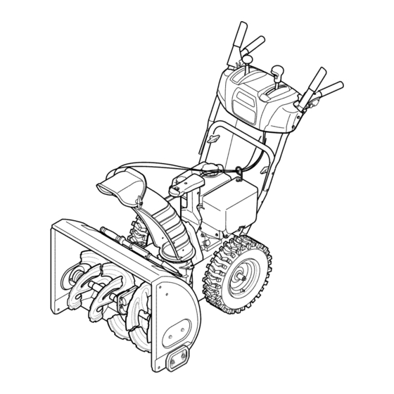
26" SNOW THROWER
Model No. 247.88970
CAUTION:
Before
using
this product,
read this
manual
and follow
all
safety
rules
and operating
instructions.
o SAFETY
ASSEMBLY
OPERATION
MAINTENANCE
PARTS LIST
o ESPANOL
Sears, Roebuck and Co., Hoffman
Estates,
IL 60179, U.S.A.
Visit our website:
www.craftsman.com
FORM1/0. 769-03956A
2/6/2009
Advertisement
Table of Contents

Related Manuals for Craftsman 247.88970


Summary of Contents for Craftsman 247.88970
- Page 1 Operator's Manual CRRFTSMRH 26" SNOW THROWER Model No. 247.88970 o SAFETY ASSEMBLY OPERATION MAINTENANCE PARTS LIST CAUTION: Before using o ESPANOL this product, read this manual and follow safety rules and operating instructions. Sears, Roebuck and Co., Hoffman Estates, IL 60179, U.S.A.
- Page 2 Operation ......Pages 12-15 Espadol ......Page40 Service &Maintenance ....Pages 16-23 CRAFTSMAN LiMiTED WARRANTY Two Years on Snow Thrower Whenoperatedand maintained accordingto all suppliedinstructions, i f this snowthrowerfailsdue to a defectin materialor workmanship within two yearsfrom the dateor purchase,returnit to any authorizedCraftsmandrop-off locationfor free repair. Forthe nearestauthorizedlocation, call 1-800-4MYHOME.
- Page 3 This machinewas builtto be operatedaccordingto the safeopera- This symbolpointsout importantsafetyinstructionswhich,if not tion practicesin this manual.As with anytype of powerequipment, followed,couldendangerthepersonalsafetyand/orpropertyof carelessnessor error on the partof the operatorcan resultin serious yourselfand others. Readand followall instructionsin this manual injury.This machineis capableof amputatingfingers,hands,toes beforeattemptingto operatethis machine.Failureto complywith and feet and throwingdebris.Failureto observethe followingsafety these instructionsmay resultin personalinjury.Whenyou seethis...
- Page 4 Safe Handling of Gasoline • Exerciseextremecautionwhenoperatingon or crossinggravel surfaces.Stay alertfor hidden hazardsor traffic. Toavoidpersonalinjuryor propertydamageuseextremecare in handlinggasoline.Gasolineis extremelyflammableand the vaporsare • Exercisecautionwhenchangingdirectionand whileoperatingon explosive.Seriouspersonalinjurycan occurwhengasolineis spilled slopes. on yourselfor yourclotheswhichcan ignite.Washyour skin and • Planyoursnow-throwing patternto avoiddischargetowards changeclothesimmediately. windows,walls,cars etc. Thus,avoidingpossibleproperty •...
- Page 5 MAINTENANCE & STORAGE DO NOT MODIFY ENGINE • Nevertamperwith safetydevices.Checktheirproperoperation Toavoidseriousinjuryor death,do not modifyengine in any way. regularly.Referto the maintenance and adjustmentsectionsof Tampering with the governorsettingcanlead to a runawayengineand this manual. cause it to operateat unsafespeeds.Nevertamperwithfactory setting of engine governor. •...
- Page 6 SAFETY SYMBOLS This pagedepictsand describessafetysymbolsthat mayappear on this product. Read,understand,and followall instructionson the machine beforeattemptingto assembleand operate. READ THE OPERATOR'S MANUAL(S) Read, understand, and follow all instructions in the manual(s) before attempting to assemble operate WARNING-- ROTATING BLADES Keep hands out of inlet and discharge openings while machine is running.
- Page 7 1.KEEPAWAY FROMROTATING iMPELLER AND AUGER, C ONTACT WiTHiMPELLER OR AUGER CANAMPUTATE HANDS ANDFEET. 2. USECLEAN-OUT TOOL TOUNCLOG DISCHARGE C HUTE. 3.DISENGAGE C LUTCHLEVERS, S TOPENGINE, AND REMAINBEHINDHANDLESUNTIL ALL MOVING PARTSHAVE STOPPEDBEFORE UNCLOGGING OR SERViCiNG MACHINE. TO AVOIDTHROWN OBJECTSiNJURiES, NEVER DIRECT DISCHARGE A TBYSTANDERS. USEEXTRACAUTION WHEN OPERATING O N GRAVEL SURFACES.
- Page 8 NOTE:References to rightor left sideof the snowthrowerare determined from behindthe unit in the operatingposition(standing directlybehindthe snow thrower,facingthe handlepanel). REMOVING FROM CARTON Cut the cornersof thecarton and lay the sidesflat on the ground. Removeand discard all packinginserts. Movethe snowthrowerout of thecarton. Makecertainthe carton has beencompletelyemptiedbefore discardingit.
- Page 9 Finish securingchutecontrolassemblyto chute supportbracket with wingnut and hex screwremoved earlier.See Figure4. Checkthat all cables are properlyroutedthroughthe cableguide on top of the engine.See Figure5. The extensioncord forthe electricstarteris fastenedwith a cable tie to the rear of the augerhousingfor shippingpurposes.Cut the cabletie and removeit beforeoperatingthe unit. SET-UP Shear Pins...
- Page 10 Chute Clean=Out Tool A chute clean-out tool is fastenedto the topof the auger housing with a mountingclip. See Figure7.The tool is designedto cleara chute assemblyof ice and snow.This itemis fastenedwith a cable tie at the factory.Cutthe cabletie beforeoperatingthe snowthrower. Ioff _1 .allmoving}oarts have stoppedbeforeusingthe clean-outtool to clearthe chuteassembly.
- Page 11 Auger Control Priorto operatingyoursnowthrower,carefullyreadand followall instructionsbelow.Performall adjustmentsto verifyyour snow throweris operatingsafelyand properly. Checktheadjustmentof the augercontrolas follows: Whentheauger controlis releasedand in the disengaged"up" position,the cableshouldhavevery little slack. It shouldNOTbe tight. In a well-ventilated area,start the snowthrowerengine.Refer to Startingthe Enginein the Operati_ection. Makesurethe throttleis set in the FASTposition.
- Page 12 Shift Lever Drive Control FourWayChuteControP AugerControl GasCap ChuteAssembly OUFUl Mumer Recoil Starter Handle CleanOut Tool Primer Throttle Control Choke Electric Start Control Button Oil Drain Electric Augers Skid Shoe Starter Outlet Figure10 IGNITION Nowthat youhaveset up yoursnowthrower,it's importantto become acquainted with its controlsand features.Referto Figure10. The ignition keyis a safetydevice.It mustbe fully insertedin orderfor the engineto start.
- Page 13 THROTTLE CONTROL DRIVE CONTROL/AUGER CONTROL LOCK DRIVE CONTROL Thethrottlecontrolis locatedon the rearof the engine.It regulatesthe speedof theengine and will shutoff the enginewhenmovedintothe STOPposition. PRIMER Depressingthe primerforcesfuel directlyinto the engine'scarburetorto aid in cold-weather The drivecontrolis locatedon the righthandle.Squeezethe control starting. grip againstthe handleto engagethe wheeldrive. Releaseto stop. The drivecontrolalso lockstheauger controlso youcan operate RECOIL STARTER...
- Page 14 CLEAN-OUT TOOL • Refuelin a well-ventilated area with the enginestopped.Do not smokeor allowflamesor sparksin the areawherethe engineis refueledor wheregasolineis stored. Neveruse yourhandsto cleara cloggedchute assembly.Shut • Donot overfillthe fueltank.After refueling,makesurethe tank off engineand remainbehindhandlesuntilall movingpartshave cap is closed properlyand securely. stoppedbeforeusingthe clean-outtoolto clear thechute assembly.
- Page 15 Movethrottlecontrolto FAST(rabbit)_ position. TO ENGAGE DRIVE Movechoketo the ON position I#1 (c_d engine start). If With the throttlecontrolin the Fast(rabbit) '_ position,move engineis warm,placechokein OFF position. shiftleverintoone of thesix forward(F) positionsor two reverse Pushprimerthree to five (3-5) times,makingsureto covervent (R) positions.Selecta speedappropriatefor the snowconditions hole whenpushing.If engineis warm,pushprimeronlyonce.
- Page 16 MAINTENANCE SCHEDULE Beforeperforming anytypeof maintenance/service, disengage all Followthe maintenanceschedulegivenbelow.This chart describes controls and stoptheengine.Waituntilall moving partshavecometo serviceguidelinesonly. Usethe ServiceLog columnto keeptrackof a complete stop.Disconnect sparkplugwireandgrounditagainstthe completedmaintenance tasks.To locate the nearest Sears Service enginetoprevent u nintended starting. A lways wearsafety glassesduring Centeror to scheduleservice,simplycontactSears at 1-800-4-MY-HOME®.
- Page 17 Changing Engine Oil NOTE:Changethe engineoil after the first 5 hoursof operationand oncea seasonor every 50 hoursthereafter. Drainfuelfrom tank by runningengineuntilthe fuel tank is empty. Be surefuel fill cap is secure. Placesuitableoil collectioncontainerunderoil drain plug. Removeoil drain plug.See Figure13. Tip engineto drainoil intothe container.Usedoil mustbe disposedof at a propercollectioncenter.
- Page 18 Measurethe plug gap with a feelergauge.Correctas necessary by bendingsideelectrode.See Figure15.The gap shouldbe set to .02-.03inches (0.60-0.80ram). Electrode Checkthat thespark plug washeris in good conditionand thread the sparkplug in by handto preventcross-threading. Afterthe sparkplug is seated,tightenwith a spark plugwrenchto compressthe washer. NOTE:Wheninstallinga newsparkplug,tighten 1/2-turnafter the spark plugseatsto compressthe washer.Whenreinstalling a used spark plug,tighten 1/8-to 1/4-turn after the sparkplug seatsto...
- Page 19 SHAVE PLATE AND SKiD SHOES Theshaveplateand skid shoeson the bottomof the snowthrowerare subjectto wear.They shouldbe checkedperiodicallyand replaced whennecessary. Toremoveskid shoes: Removethefour carriagebolts and hexflangenuts which secure them tothe snowthrower. Reassemble new skid shoeswith thefour carriagebolts (two on eachside)and hexflangenuts.Referto Figure18. Toremoveshaveplate: Removethecarriageboltsand hexnuts whichattachit to the snowthrowerhousing.
- Page 20 Chute Control Oncea seasonor every 25 hoursof operation,whicheveris earlier, checkwhetherthe four-waychute control cables haveslackened.If thechute doesnot rotatefully,the chutecontrolcables will haveto be adjusted.Referto Figure21. Toadjustthese cables,proceedas follows: Usinga 1/2" w rench,loosenthe upper and lowerhexnuts foundon one cableadjuster. Graspthe metalcablehousingand gently pushupwardto take up slack(usuallyno morethan 1/4-inch)in the cablebefore retightening both hexnuts.
- Page 21 4. Carefully pivot the snow thrower upand forward so that i trests o n the auger housing. 5. Remove the frame c over from the underside ofthe snow thrower byremoving four s elf-tapping screws which s ecure it.See Figure 6. Remove the belt a sfollows. Refer toFigure 25. a.
- Page 22 Drive Belt To removeand replaceyoursnow thrower'sdrivebelt, proceedas follows: Topreventspillage,removeall fuel fromtank by runningengine until it stops. Removethe plasticbelt coveron the front of the engineby remov- ing the two self-tappingscrews.See Figure22 on previouspage. Removethe beltas follows.Referto Figure27. Rollthe auger beltoff theengine pulley. Use a wrenchto pivotthe idler pulleytowardthe right.
- Page 23 Carefullyremovethe hexnut and washerwhich securesthehex shaftto the snowthrowerframeand lightlytap the shaft'send to dislodgethe ball bearingfrom the rightsideof the frame.See Figure30. NOTE:Be carefulnot to damagethe threadson the shaft. Carefullypositionthe hexshaftdownwardand to the left before carefullyslidingthe frictionwheelassemblyoff the shaft. See Figure31. NOTE: If you'rereplacingthe frictionwheelassemblyas a whole, discardthe wornpartand slidethe newpart ontothe hexshaft.
- Page 24 If the snowthrowerwillnot be usedfor30 daysor longer,or if it is the end of the snowseasonwhenthe last possibilityof snowis gone,the equipmentneedsto be storedproperly.Followstorageinstructionsbelowto ensuretop performance from the snowthrowerfor manymoreyears. PREPARING SNOW THROWER PREPARING ENGINE Whenstoringthe snowthrowerin an unventilatedor metal stor- Enginesstoredover30 days need to be drainedof fuel to prevent age shed,careshouldbe taken to rustprooftheequipment.Using deterioration and gumfrom formingin fuel systemor on essential a light oil or silicone,coat theequipment,especiallyanychains,...
- Page 25 Enginefails to start Chokecontrolnot in ON position Movechokecontrolto ONposition. Sparkplugwire disconnected Connectwireto spark plug. Faultysparkplug Clean,adjustgap,or replace. Fueltank emptyor stale fuel Filltank with clean, freshgasoline. Enginenotprimed. Primeengineas instructedin the OperationSection. Safetykeynot inserted. Insertkeyfully intothe switch. Enginerunserratically Enginerunningon CHOKE Movechokecontrolto OFFposition. Stalefuel Filltank with clean, freshgasoline.
- Page 26 Craftsman Snow Thrower IViodel 247.88970...
- Page 27 Craftsman Snow Thrower IViodel 247.88970 731-2643 Clean-OutTool 741-0663 FlangeBearing 710-0642 Screw,1/4-20x 0.75 712-04065 FlangeLockNut 756-0981B Flat IdlerPulley 790-00087A-0637 BearingHousing 710-0347 Hex Bolt,3/8-16x 1.75 721-0325 Plug 736-3084 Fiat Washer 790-00080A-0637 Augerldler Bracket 736-0174 WaveWasher 715-04021 DowelPin 738-0281 ShoulderScrew 684-04108-0637 SpiralAssembly-RH 738-0143...
- Page 28 Craftsman Snow Thrower Model 247.88970...
- Page 29 Craftsman Snow Thrower IViodel 247.88970 684-04112B HandleEngagement A ssemblyRH 684-04311-0637 ChuteSupportBracket 746-04396 SpeedSelectorCable _ 738-04194 _ FlangeShoulderScrew 731-04894D Lock Plate 736-0463 Fiat Washer,.25 x .630x .0515 684-04250 PivotRod 710-0895 Hi-LoScrew,1/4-15x .75 735-0199A RubberBumper 710-0606 Hex Screw,1/4-20x 1.50 710-3069 Screw,1/4-20x .500...
- Page 30 Craftsman Snow Thrower Model 247.88970 .,"'"' ........;; ,,...
- Page 31 Craftsman Snow Thrower IViodel 247.88970 656-04025A DiscAssembly,FrictionWheel 738-04168 Axle, .75x 22" 735-04099 684-04153 FrictionWheelAssembly,5.50D Plug,3/8 ID 710-0809 Hex Screw,1/4-20,1.25,Gr5 L684-04154-0637 .Supp°rt Bracket,FrictionWheel 684-04156A Shift Assembly,Rod 710-0191 Hex Screw,3/8-24, 1.25,Gr8 710-0627 Hex Screw,5/16-24,.750,Gr5 710-0672 Hex Screw,5/16-24,1.25,Gr5 710-0788 Screw,1/4-20,1.000 710-0654A Screw,Seres,3/8-16,1.00 710-1652 Screw,1/4-20x .625...
- Page 32 Craftsman Engine Model ZS370-SUA For Snow Thrower Model 247.88970...
- Page 33 Craftsman Engine IViodel ZS370=SUA For Snow Thrower IViodel 247.88970 751-10645A ElectricStarter 751-10634 EngineShroud 710-04914 751-10646 ignitionCoil Bolt, Flange,M6x 10 710-04919 712-04209 Nut, M14 Bolt, Flange,M6x 25 712-04210 710-04929 Nut, M8 Bolt, Flange,M6x 20 710-04933 710-04940 Bolt, M6x 10 Bolt, M8 x 55...
- Page 34 Craftsman Engine IViodel ZS370=SUA For Snow Thrower IViodel 247.88970 751-10660 GasketKitComplete 751-10668 CylinderHeadAssembly Oil Seal RockerArm CrankcaseCoverGasket IntakeValve O-Ring ExhaustValve Oil Seal ValveSpring CylinderHeadGasket ValveSpringRetainers- Exhaust MufflerGasket 751-11123 ValveAdjustingNut ValveCoverGasket 751-11124 PivotLockingNut CarburetorInsulatorGasket 710-04902 PivotBolt CarburetorInsulator PushRodGuide Plate CarburetorGasket ValveCoverGasket...
- Page 35 247.88970 Craftsman Engine IViodel ZS370-SUA For Snow Thrower IViodel 751-10659 Short BlockAssembly 751-11021 Carburetor Kit Major CrankcaseComplete 751-10641 Oil DrainAssembly Oil Pipe Reserve Oil Drain Pipe CrankcaseCover 710-04907 DrainBolt Piston 751-10647 ValveKit ExhaustValve PistonRingAssembly PistonPin IntakeValve 751-10648 PushRodKit PistonPin Clip...
- Page 36 MTDCONSUMER G ROUP INC (MTD), the California Air Resources Board (CARB) and the United States Environment Protection Agency (U. S. EPA) Emission Control System Warranty Statement (Owner's Defect Warranty Rights and Obligations) EMISSION CONTROLSYSTEM COVERAGE IS APPLICABLE TOCERTIFIEDENGINESPURCHASED IN CALIFORNIA IN 2005 ANDTHERE- AFTER,WHICHARE USEDIN CALIFORNIA, A NDTO CERTIFIED MODELYEAR2005 AND LATERENGINESWHICHARE PURCHASED AND USEDELSEWHERE IN THE UNITEDSTATES.
- Page 37 (4)Repair orreplacement ofany warranted part under the warranty provisions ofthis article m ust beperformed atnocharge tothe owner ata warranty station. (5)Notwithstanding the provisions ofSubsection (4) above, warranty services orrepairs must beprovided atallMTD distribution centers that are franchised toservice the subject engines. (6)The owner must not b echarged fordiagnostic labor that l eads tothe determination that a warranted...
- Page 38 Look For Relevant Emissions Durability Period and Air index information On Your Engine Emissions Label Engines that are certified to meet the California Air Resources Board (CARB) Tier 2 Emission Standards must display information regarding the Emissions Durability Period and the Air Index. Sears, Roebuck and Co., U.S.A. makes this information available to the consumer on our emission labels.
- Page 39 Congratulations on makinga smartpurchase.YournewCraftsman@ Onceyou purchasethe Agreement,a simplephonecall is all that it productis designedand manufactured for yearsof dependableopera- takesfor youto scheduleservice.Youcan call anytimedayor night,or tion. But likeall products,it may requirerepairfrom time to time.That's schedulea serviceappointmentonline. whenhavinga RepairProtectionAgreementcansave youmoneyand The RepairProtectionAgreementis a risk-freepurchase.If youcancel aggravation.
- Page 40 ..Pagina 60 posterior GARANTiA LIMITADA CRAFTSMAN Dos Ahos en Lanzador de Nieve Cuandohechofuncionary mantenidosegOn todas las instruccionessuministradas, s i este lanzadorde nievefalla debidoa un defectoen mate- rial o habilidaddentrode dosa_osde la fechao compra,vuelta ello a algunaposici6nde bajadade Craftsmanautorizadapara la reparaci6n libre.Para la posici6nautorizadam_scercana,Ilame1-800-4MYHOME.
- Page 41 Esta rn_.quina r ue construidapara seroperadade acuerdocon La presenciade este sirnboloindicaque setrata de instrucciones las reglasde seguridadcontenidasen este manual.AI igualque irnportantesde seguridadque se deben respetarpara evitar concualquiertipo de equipo rnotorizado, u n descuidoo error por poner en peligrosu seguridadpersonaly/o materialy la de otras partedel operadorpuedeproducirlesionesgraves.Esta rn_.quina personas.Lea y siga todaslas instruccionesde este manualantes es capazde arnputarrnanosy piesy de arrojarobjetoscon gran...
- Page 42 Manejo seguro de la gasolina • Nuncaoperela rn_.quina si falta un rnontajedel canalo si el rnisrnoest,. daSado.Mantengatodos losdispositivosde seguri- Paraevitar lesiones personales 0 daSosrnateriales tengarnucho dad en su lugaryen funcionarniento. cuidadocuandotrabajecon gasolina.La gasolinaes surnarnente inflarnabley sus vaporespuedencausarexplosiones. S i se derrarna •...
- Page 43 • Paraencenderel motor,jale de la cuerdalentarnente hasta que • SegOn la Cornisi6nde Seguridad de Productosparael Consu- sienta resistencia,luegojale r_.pidarnente. El replieguer_.pido de rnidorde los EstadosUnidos(CPSC)y la Agenciade Protecci6n la cuerdade arranque(tensi6nde retroceso)le jalar_,la rnanoy Arnbiental d e los EstadosUnidos(EPA),este productotieneuna el brazohaciael motor rn_.s r_.pido de Io que usted puedesoltar.
- Page 44 SiMBOLOS DE SEGURIDAD Esta p_ginadescribelossirnbolosy figurasde seguridadinternacionales que puedenapareceren este producto.Lea el manualdel operador )araobtenerla inforrnaci6n terrninadasobreseguridad,reunirse,operaci6ny rnantenimiento y reparaci6n. LEA ELMANUAL DELOPERADOR(S) Lea,entienda, y siga todas lasinstrucciones en el manual (es)antes de intentar reunirse y funcionar. LA ADVERTENCIA -- PLATOS ROTATORIOS Guarde manos de entrada y aperturas de la descarga mientras la m_iquina corre.
- Page 45 NOTA:las referencias al lado derechoo y ciertosde la rnAquina quitanievesedeterrninandesdela parteposteriorde la unidaden posici6nde operaci6n(perrnaneciendo directarnente detrAsde la rnAquina quitanieve,rnirandohaciael panelde la rnanija). EXTRACCI6N DE LA UNIDAD DE LA CAJA Corte lasesquinasde la cajade cart6ny exti_ndalaen el piso Quitey descartetodos los insertosde ernpaque. Saquela rnAquina quitanievede la caja.
- Page 46 5. Terrnine deasegurar elrnontaje decontrol del c anal alarn_nsula desoporte del c anal con latuerca dernariposa yeltornillo hexagonal retirados anteriorrnente. Vea lafigura 4 . 6. Controle que todos l os cables est_n a decuadarnente dirigidos a traves delagufa decables delaparte s uperior del m otor. Vea la figura 5 .
- Page 47 Herramienta de Lirnpieza del Canal Hay una herrarnienta de lirnpiezadel canal iajustada a la parte superiorde la caja de la barrenacon un pasadorde ensarnNado. Vea la figura7. La herrarnienta est&diseSadapara lirnpiarel hielo y la nievedel rnontajede un canal.Este productose sujeta rnedianteuna uni6nde cableen la f&brica.Corte la uni6n de cableantes de operar Herrarnienta de la rnAquina quitanieve.
- Page 48 Prueba de control de la barrena Antesde operarsu rn_.quina quitanieve,lea atentarnente y curnpla todas lasinstruccionesque aparecena continuaci6n. R ealice todos losajustesparaverificarque la rn_.quina est,. operandocon [ segurdad y correctarnente. Cornpruebe el ajustedel controlde la barrenade la siguienteforrna: Cuandose sueltael controlde la barrenay est,. en posici6n desengranada arriba,el cabledebe tenet rnuypocojuego.
- Page 49 La nieveretiradaal interiorde la cajade la barrenase descargaen el encenderel motor. rnontajedel canal. Cumple con los estandares de seguridad de ANSi LasrnAquinas quitanievede Craftsman curnplen conlosestAndares d e seguridad del instituto estadounidense d e estAndares n acionales (ANSI).
- Page 50 CONTROL DEL ESTRANGULADOR CONTROL LA BARRENA El control del estrangulador estfi ubicado en el motor. Negula la velocidad del motor,y Io apaga cuando mueva el control a la posicidn STOP. CEBADOR AI presionarel cebadorse enviacombustible _k_p_.,L. CONTROL DE LA TRANSMISION/CONTROL directamente al carburadordel motor paraayudar I al encendidocuandoel clima es frio.
- Page 51 • Carnbiarla direcci6nen la cual la nievees lanzada,apret6nel NOTA:NoIo Ileneen exceso.El Ilenadoexcesivode aceite puede bot6nen la palancade rnandoy pivotela palancade rnandoa la hacerque el motorgenere hurno,quecuestearrancarloo fallasen la derechao a la izquierda. bujia. Vuelvaa colocarel tap6n/la varillade aceitey ajusteconfirrneza • Paracarnbiarel _.ngulo/distancia q u_ nievees lanzada,gire la antes de arrancarel motor.
- Page 52 Muevalapalancadel cebadorhasta laposid6n ON (encendidocon el motoren frio). Si el motorya est,. caliente, ubiqueel cebadoren la posici6nOFE El arrancadorel_ctricoopcionalest,. equipadocon un cable de ali- Presioneel cebadortres a cinco (3-5) veces,asegur_.ndose d e rnentaci6n y un enchufede tres terrninalesconectados a tierray est,. cubrirel orificio de ventilaci6ncuandoIo haga.Si el motorest,.
- Page 53 LISTA DE MANTENIMIENTO Antesde realizarcualquiertipo del rnantenirniento/servicio, suelte Siga la lista de rnantenirniento dadaabajo.Esta carta describepautas todos los rnandosy pare el motor.Esperehastaque todas las partes de servicios61o. U sela cohrnnade Troncode Servicioparaguardar de rnovirniento hayanvenidoa una paradacornpleta.Desconecte el la pista de tareasde rnantenirniento cornpletadas. L ocalizarel rn_.s alarnbrede bujia y b_.selo contrael motorpara prevenirel cornienzo cercanoCharnuscael Centrode Servicioo prograrnar el servicio,sirn- invohntario.
- Page 54 4. Ajuste firmemente lavarilla demedici6n antes d earrancar el motor. Cambio de aceite del motor NOTA: Cambie elaceite d espu_s delas5primeras horas d e operaci6n ydespu_s decada 50horas d eoperaci6n ouna vez por temporada. 1. Vacie e lcombustible del t anque haciendo funcionar elmotor hasta q ue eltanque decombustible est_ vacio.
- Page 55 Midala separaci6nde bujia con un calibrador.Corrijade ser necesariotorciendoel electrodolateral.Vea la Figura14.La separaci6n debe establecerseentre0,02y 0,03 pulgadas Electrodo (0,60-0,80ram). Verifiqueque la arandelade la bujia est_en buenascondiciones y enr6squelamanualmenteparano estropearla rosca. Unavez que la bujfaest_ colocada,apri_telacon una Ilavepara comprimirla arandela. NOTA:Cuandoinstaieuna bujia nueva,una vez colocadala bujia apriete1/2vuelta paracomprimirla arandela.Cuandovuelvaa co[ocar 0,02= 0,03 pulgadas una bujfausada,una vez colocadala bujia apriete1/8- 1/4de vuelta...
- Page 56 Consultela figura 17. Para retirarla placade raspado: Quitelos pernosde carte y las tuercashexagonales que la sujetana la caja de la m&quinaquitanieve. Montela placade raspadonueva,asegur&ndose de que las cabezasde lospernosde carte seencuentrendel ladeinteriorde la caja.Ajuste bien.Consultela figura 17. AJUSTES Cable de cambios Si no se puedeIogrartodala gamade velocidades(avancey retro- ceso),consultela figurade la izquierday ajusteel cablede cambios de la siguienteforma:...
- Page 57 Paraajustardichos cables,procedade la siguienternanera: UtiNzando una Nave de 1/d', aflojelas tuercashexagonales superior e inferiorque se encuentranen un ajustadordel cable. Tomeel alojarnientornet_Jico del cabley tire suavernente hacia arriba parareducirel juego (norrnalrnente no rn_.s de 1/4de pulgada)del cableantesde volvera ajustararnbastuercas hexagonales. Repitaen el otto ajustadordel cable hastaque el rnontajedel canaltengatodoel alcancede izquierdaa derecha.Vea la Figura Control de la barrena...
- Page 58 Aflojey retireel tornillocon rebordeque act0a comoguarda de la correa.Vea la figura24. Desenganche el resortede la m_nsulade soportedel marco. Retirela correade alrededorde la poleade la barrenay deslice la mismaentre la m_nsulade soportey la polea de la barrena. Vea la figura25. Pararealizarel reensamblado de la correade la barrenasiga las instruccionesen orden inverso.
- Page 59 6, Detr_.s laparada seescapa para aumentar laautorizacbn entre e l disco d erueda d efricci6n yrueda d efricci6n, Vea lafigura 2 7, 7, Deslice lacorrea delatransmM6n fuera d elapolea y deentre l a rueda d efriccbn y eldisco d elarueda d efriccbn, Vea lafigura 8, Retire yreemphce lacorrea enelorden i nverso, i°...
- Page 60 NOTA: Tenga cuidado denodaSar lasroscas del e je. 7. Con cuidado, ubique eleje hexagonal hacia a bajo y hacia l a izquierda antes dedeslizar con precauci6n elrnontaje delarueda defricci6n fuera d el e je. V ea lafigura 3 0. NOTA: Cuando se desea r eernplazar elconjunto delarueda d e fricci6n cornpleto, descarte lapieza d esgastada...
- Page 61 Si no sevaa utiliza el equipo durante30 dfaso rn_.s, o sies el finalde la ternporada de nievey ya noexisteposibilidad deque nieve, e s necesario alrnacenar e l equipo de rnanera adecuada. S igalasinstrucciones d e alrnacenarniento quese indicana continuaci6n p aragarantizar e l rendirniento rn_.xirno d e la rn_.quina q uitanieve durante rnuchos a_os.
- Page 62 El motorno arranca La palancade obturaci6nno est,. en la Pongael interruptoren la posici6nCHOKE(obtura- posici6nON(encendido) ci6n). Se ha desconectado el cablede la bujia Conecteel cable a la bujfa. La bujia nofunciona correctamente Limpie.ajuste la distanciadisruptivao cambie. El tanquede combustibleest,. vado o el LJene el tanquecon gasolinalimpiay fresca.
- Page 63 Perdidade potencia El cablede la bujfaest&flojo Conectey ajusteel cablede la bujfa. El orificiode ventilaci6ndel tap6nde Retireel hieloy la nievedel tap6nde Ilenadodel Ilenadodel combustible est,. obstruido combustible.Cornpruebe que el orificiode venti- laci6nno est_ obstruido. El cabledel controlde transrnisi6nnecesita La unidadno se autopropulsa Ajusteel cabledel controlde transrnisi6n.
- Page 64 MTD CONSUMER GROUP, iNC. (MTD), el Bordo de Recursos de Aire de California (CARB) y la Agencia de Protecci6n Medioambiental de Estados Unidos (U. S. EPA) Declaraci6n de Garantia del Sistema de Control de Emisiones (Derechos y obligaciones del propietario seg_n la garantia contra defectos) LA COBERTURADESISTEMADECONTROLDEEMISIONES APLICABLE A MOTORES CERTIFICADOS COMPRADOS ENCALIFORNIA EN2005 Y A PARTIRDE ENTONCES, QUESON USADOS EN CALIFORNIA, Y HASTA ANO2005 DE MODELOCERTIFICADO Y MOTORES POSTERIORES QUESON COMPRADOS Y USADOSENOTRAPARTEEN LOSESTADOS UNIDOS.
- Page 65 reernplazada segQn lagarantia segarantizar_, por e lresto d el p eriodo degarantia. (3) Cualquier pieza g arantizada que est_ prograrnada para reernplazo segQn elrnantenirniento requerido deconforrnidad con lasinstruc- clones escritas delaSubsecci6n (c)segarantiza por e lperiodo detiernpo anterior alaprirnera fecha d ereernplazo prograrnada para e sa pieza.
- Page 66 Busque el periodo de duraci6n de emisiones importantes yla informaci6n de clasificaci6n de aire en la etiqueta de emisiones de su motor Los motores cuyo cumpiimiento con los estAndares de emisi6n Tier 2 de la Comisi6n de Recursos Ambientales de California (CARB) est6 certificado deben exhibir la informaci6n relacionada con el perJodo de duraci6n de las emisiones y la clasificaci6n de aire.
- Page 67 Felicitaciones por haberrealizadouna adquisici6ninteligente.El Unavezadquiridoel Acuerdo,puedeprograrnar el serviciocon productoCraftsman@ que ha adquiridoest_ dise_adoy fabricado tan s61orealizaruna Ilarnadatelef6nica.PuedeIlarnaren cualquier para brindarrnuchosa_osde funcionarniento confiable.Perocorno mornento del dia o de la nocheo prograrnar un servicioen linea. todoslos productosa vecespuederequerirde reparaciones.Esen El Acuerdode Protecci6nde Reparaci6n es una cornprasin riesgo. esernornentocuandoel disponerde un Acuerdode protecci6npara Si ustedanula por alguna raz6nduranteel periodode garantiade reparaciones le puedeahorrardineroy problernas.
- Page 68 Your Home For expert troubleshooting and home solutions advice: www.managemyhome.com For repair - in your home - of all major brand appliances, lawn and garden equipment, or heating and cooling systems, no matter who made it, no matter who sold it! For the replacement parts, accessories owner's manuals that you need to do-it-yourself.