Table of Contents
Advertisement
The Chamberlain Group, Inc.
845 Larch Avenue
Elmhurst, Illinois 60126-1196
www.liftmaster.com
O O W W N N E E R R ' ' S S M M A A N N U U A A L L
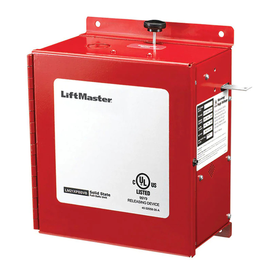
M M O O D D E E L L S S
L L M M 2 2 1 1 X X P P B B B B
L L M M 2 2 1 1 X X P P B B B B V V B B
E E X X T T E E N N D D E E D D P P E E R R F F O O R R M M A A N N C C E E R R E E L L E E A A S S E E D D E E V V I I C C E E
APPROVED
Advertisement
Table of Contents

Related Manuals for Chamberlain LiftMaster LM21XPBB


Summary of Contents for Chamberlain LiftMaster LM21XPBB
- Page 1 845 Larch Avenue Elmhurst, Illinois 60126-1196 www.liftmaster.com O O W W N N E E R R ’ ’ S S M M A A N N U U A A L L M M O O D D E E L L S S...
-
Page 2: Table Of Contents
ADVERTENCIA The LiftMaster ® LM21XPBB and LM21XPBBVB Release Device is Form C dry contact relay. The release device features include a UL/ULC listed normally energized fail-safe device designed for 10, 20, 30 or 60 second delay on alarm, closed door detection... -
Page 3: Agency Requirements
Battery, Maximum charge current COMMON ALARM AND ATTENTION .150Amps TROUBLE RELAYS: 5A 125Vac 60Hz BATTERY STANDBY TIME: LM21XPBB, 72 Hours (MAX. CONTACT RATING) 1A 24Vdc Resistive LM21XPBBVB, 24 Hours MECHANICAL SPECIFICATIONS LOAD RATING: Support and Release 40 lbs. Max. WEIGHT: Approximately 18 lbs. -
Page 4: Installation
I N S T A L L A T I O N NING WARNING IMPORTANT INSTALLATION INSTRUCTIONS WARNING WARNING To reduce the risk of SEVERE INJURY or DEATH: 1. READ AND FOLLOW ALL INSTALLATION WARNINGS 4. Concrete anchors MUST be used if mounting release AND INSTRUCTIONS. -
Page 5: Caution
WARNING W I R I N G WARNING WARNING To reduce the risk of SEVERE INJURY or DEATH: • ALL power wiring should be on a dedicated circuit and well protected. The location of the power disconnect should be • ALL electrical connections MUST be made by a qualified visible and clearly labeled. -
Page 6: Wire Routing
W I R I N G WIRE ROUTING Mechanical Reset Plunger High Voltage Wiring Power Strip Low Voltage Wiring Ground Annunciator Wiring with Sleeve Voice Board Wiring PARTS KIT LMEOLRES-10 Wire Jumper 10k Ohm Resistor Refer to wiring section for proper application of these parts. -
Page 7: Wiring Diagram
W I R I N G WIRING DIAGRAM Replace batteries every 2 years. Field wiring shall consist of 22-18 AWG wiring. Use only 250Vac, 3 Amp, 3 AG, Slo-Blo fuses. 1. Supervised, power limited circuit, 20 Ohm maximum line impedance. Solenoid 2. -
Page 8: Connections Of Initiating Devices And Accessories
W I R I N G CONNECTIONS OF INITIATING DEVICES AND WARNING WARNING ACCESSORIES A maximum of 4 smoke detectors may be installed with this To prevent possible SERIOUS INJURY or DEATH: device. Refer to NFPA 72 and NFPA 80 for instructions •... -
Page 9: Optional Connections
WARNING W I R I N G CONNECTIONS OF INITIATING DEVICES AND CAUTION CAUTION ACCESSORIES (cont’d) Relay Module Installation To prevent DAMAGE to the circuit board, ALL connections from terminals 3 through 16 MUST be dry contact type. In lieu of smoke detectors, the release device may be put into alarm by the fire alarm control panel. - Page 10 W I R I N G OPTIONAL CONNECTIONS (cont’d) VOICE BOARD OPTION The voice board provides one of two verbal warnings that the fire door is closing. Typically, depending on the length of the delay FIGURE 11 chosen on the release device, a warning tone will occur prior to the message, which is approximately 10 seconds in length (for example, a 20 second delay setting on the release device will result in a 10 second warning tone followed by the verbal warning...
-
Page 11: Testing
T E S T I N G TEST PROCEDURES WARNING WARNING TO BE PERFORMED BY FACTORY AUTHORIZED PERSONNEL ONLY! CLEAR FIRE DOOR OPENING AND PROHIBIT TRAFFIC To prevent possible SERIOUS INJURY or DEATH: THROUGH DOOR OPENING WHILE TESTING! • Clear fire door opening and prohibit ALL traffic through door CAUTION opening while testing. -
Page 12: Troubleshooting
T R O U B L E S H O O T I N G OPERATIONAL CHECKLIST WARNING WARNING POWER To prevent possible SERIOUS INJURY or DEATH: Is the red LED, labeled “Power,” located on the bottom of the • Clear fire door opening and prohibit ALL traffic through door CAUTION enclosure lit? opening while trouble shooting. -
Page 13: Maintenance
WARNING WARNING M A I N T E N A N C E MAINTENANCE REQUIREMENTS CAUTION WARNING WARNING The release device has no scheduled maintenance requirements. The unit has been designed and tested for use in dry, indoor To avoid SERIOUS PERSONAL INJURY or DEATH: locations. -
Page 14: Accessories And Repair Parts
A C C E S S O R I E S A N D R E P L A C E M E N T P A R T S ACCESSORIES ITEM PART # DESCRIPTION ITEM PART # DESCRIPTION LM8100 Smoke Detector - 120V Photo 12 LMEH1224ADA Horn - 12/24Vdc... -
Page 15: Appendix
LMHS2475ADA 24Vdc Horn/Strobe P1224MC, P2R LMEH1224ADA 24Vdc Horn H12/24 LM8SP Speaker SP201R END-OF-LINE DEVICE SYSTEM SENSOR SPACE AGE LIFTMASTER NO. MODEL NO. DESCRIPTION MODEL NO. ELECTRONICS NO. LMEOLRES10 10 kOhm End-of-Line Resistor LMEOLRES-10 LMEOLR1224 End-of-Line Relay EOLR-1 LMEOLR120 End-of-Line Relay PAM-1 NOTE: Certain accessories above will require a separate power source. - Page 16 01-32051D © 2008, The Chamberlain Group, Inc. 2/11/08 All Rights Reserved...