ASROCK Z68 Extreme4 Gen3 User Manual
User manual
Hide thumbs
Also See for Z68 Extreme4 Gen3:
- Quick installation manual (322 pages) ,
- User manual (81 pages) ,
- Installation manual (15 pages)

Related Manuals for ASROCK Z68 Extreme4 Gen3


Summary of Contents for ASROCK Z68 Extreme4 Gen3
-
Page 1: User Manual
Z68 Extreme4 Gen3 User Manual Version 1.0 Published June 2011 Copyright©2011 ASRock INC. All rights reserved. -
Page 2: Copyright Notice
In no event shall ASRock, its directors, of cers, employees, or agents be liable for any indirect, special, incidental, or consequential damages (including damages for... -
Page 3: Table Of Contents
, 3-Way CrossFireX and Quad CrossFireX Operation Guide ........27 2.9 Dual Monitor and Surround Display Features ....33 2.10 ASRock Smart Remote Installation Guide ..... 36 2.11 Jumpers Setup ............37 2.12 Onboard Headers and Connectors ......38 2.13 Smart Switches ............ - Page 4 ® 2.22 Installing Windows 7 / 7 64-bit / Vista / Vista 64-bit / XP / XP 64-bit Without RAID Functions ....57 ® 2.22.1 Installing Windows XP / XP 64-bit Without RAID Functions............57 ® 2.22.2 Installing Windows 7 / 7 64-bit / Vista Vista 64-bit Without RAID Functions ....
-
Page 5: Introduction
In case any modi cations of this manual occur, the updated version will be available on ASRock website without further notice. You may nd the latest VGA cards and CPU support lists on ASRock website as well. ASRock website http://www.asrock.com... -
Page 6: Specifications
Specifications - ATX Form Factor: 12.0-in x 9.6-in, 30.5 cm x 24.4 cm Platform - All Solid Capacitor design (100% Japan-made high-quality Conductive Polymer Capacitors) ® - Supports 2nd Generation Intel Core i7 / i5 / i3 in LGA1155 Package - Advanced V8 Power Phase Design ®... - Page 7 - Supports DisplayPort with max. resolution up to 2560x1600 @ 60Hz - Supports Auto Lip Sync, Deep Color (12bpc), xvYCC and HBR (High Bit Rate Audio) with HDMI (Compliant HDMI monitor is required) (see CAUTION 7) - Supports HDCP function with DVI, HDMI and DisplayPort ports - Supports Full HD 1080p Blu-ray (BD) / HD-DVD playback with DVI, HDMI and DisplayPort ports...
- Page 8 - Drivers, Utilities, AntiVirus Software (Trial Version), Support CD CyberLink MediaEspresso 6.5 Trial, ASRock Software Suite (CyberLink DVD Suite - OEM and Trial; ASRock MAGIX Multimedia Suite - OEM) - ASRock Extreme Tuning Utility (AXTU) (see CAUTION 9) Unique Feature...
- Page 9 Certifi cations - ErP/EuP Ready (ErP/EuP ready power supply is required) (see CAUTION 20) * For detailed product information, please visit our website: http://www.asrock.com WARNING Please realize that there is a certain risk involved with overclocking, including adjusting the setting in the BIOS, applying Untied Overclocking Technology, or using the third-party overclocking tools.
- Page 10 6-channel, and 8-channel modes. Please check the table on page 14 for proper connection. ASRock Extreme Tuning Utility (AXTU) is an all-in-one tool to ne-tune different system functions in a user-friendly interface, which is including Hardware Monitor, Fan Control, Overclocking, OC DNA and IES. In Hardware Monitor, it shows the major readings of your system.
- Page 11 10. ASRock Instant Flash is a BIOS ash utility embedded in Flash ROM. This convenient BIOS update tool allows you to update system BIOS ® without entering operating systems rst like MS-DOS or Windows . With this utility, you can press <F6> key during the POST or press <F2> key to BIOS setup menu to access ASRock Instant Flash.
- Page 12 16. ASRock On/Off Play Technology allows users to enjoy the great audio ex- perience from the portable audio devices, such like MP3 player or mobile phone to your PC, even when the PC is turned off (or in ACPI S5 mode)! This motherboard also provides a free 3.5mm audio cable (optional) that...
-
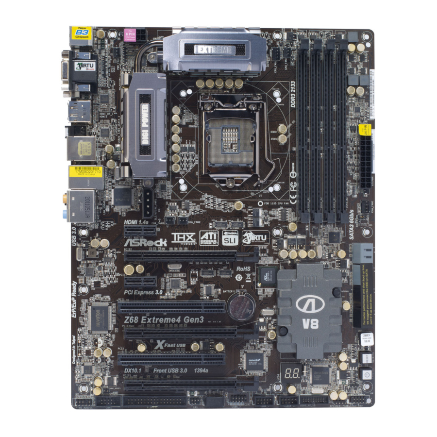
Page 13: Motherboard Layout
RJ-45 B: USB5 CHA_FAN3 CLRCMOS1 CHA_FAN2 HDMI 1.4a PCIE1 PCIE2 RoHS PCIE3 Intel PCI Express 3.0 CMOS PCI1 Battery Z68 Extreme4 Gen3 PCIE4 64Mb BIOS Fast USB PCI2 RSTBTN AUDIO CODEC DX10.1 Front USB 3.0 1394a PWRBTN Debug PCIE5 PLED1... -
Page 14: I/O Panel
I/O Panel USB 2.0 Ports (USB01) ** 10 Front Speaker (Lime) D-Sub Port Microphone (Pink) DisplayPort (HDMI_DP_1) USB 3.0 Ports (USB45) USB 2.0 Ports (USB23) IEEE 1394 Port (IEEE 1394) LAN RJ-45 Port *** 14 eSATA3 Connector Central / Bass (Orange) Clear CMOS Switch (CLRCBTN) Rear Speaker (Black) HDMI Port... - Page 15 To enable Multi-Streaming function, you need to connect a front panel audio cable to the front panel audio header. After restarting your computer, you will nd “Mixer” tool on your system. Please select “Mixer ToolBox” , click “Enable playback multi-streaming”, and click “ok”.
-
Page 16: Installation
Chapter 2: Installation This is an ATX form factor (12.0" x 9.6", 30.5 x 24.4 cm) motherboard. Before you install the motherboard, study the con guration of your chassis to ensure that the motherboard ts into it. Make sure to unplug the power cord before installing or removing the motherboard. -
Page 17: Cpu Installation
2.3 CPU Installation For the installation of Intel 1155-Pin CPU, please follow the steps below. Load Plate Load Lever Socket Body Contact Array 1155-Pin Socket Overview Before you insert the 1155-Pin CPU into the socket, please check if the CPU surface is unclean or if there is any bent pin on the socket. Do not force to insert the CPU into the socket if above situation is found. - Page 18 Step 3. Insert the 1155-Pin CPU: Step 3-1. Hold the CPU by the edge where is marked with black line. Step 3-2. Orient the CPU with IHS (Integrated Heat Sink) up. Locate Pin1 and the two orientation key notches. orientation key notch alignment key Pin1 Pin1...
-
Page 19: Installation Of Cpu Fan And Heatsink
Installation of CPU Fan and Heatsink This motherboard is equipped with 1155-Pin socket that supports Intel 1155-Pin CPU. Please adopt the type of heatsink and cooling fan compliant with Intel 1155- Pin CPU to dissipate heat. Before you installed the heatsink, you need to spray thermal interface material between the CPU and the heatsink to improve heat dis- sipation. -
Page 20: Installation Of Memory Modules (Dimm)
2.5 Installation of Memory Modules (DIMM) This motherboard provides four 240-pin DDR3 (Double Data Rate 3) DIMM slots, and supports Dual Channel Memory Technology. For dual channel con g- uration, you always need to install identical (the same brand, speed, size and chip-type) DDR3 DIMM pair in the slots: You have to install identical DDR3 DIMM pair in Dual Channel A (DDR3_A1 and DDR3_B1;... -
Page 21: Installing A Dimm
Installing a DIMM Please make sure to disconnect power supply before adding or removing DIMMs or the system components. Step 1. Unlock a DIMM slot by pressing the retaining clips outward. Step 2. Align a DIMM on the slot such that the notch on the DIMM matches the break on the slot. -
Page 22: Expansion Slots (Pci And Pci Express Slots)
2.6 Expansion Slots (PCI and PCI Express Slots) There are 2 PCI slots and 5 PCI Express slots on this motherboard. PCI slots: PCI slots are used to install expansion cards that have the 32-bit PCI interface. PCIE slots: PCIE1 / PCIE3 (PCIE 2.0 x1 slot) is used for PCI Express cards with x1 lane width cards, such as Gigabit LAN card, SATA2 card, etc. -
Page 23: Tm And Quad Sli Tm Operation Guide
2.7 SLI and Quad SLI Operation Guide ® This motherboard supports NVIDIA and Quad SLI (Scalable Link Interface) technology that allows you to install up to three identical PCI Express x16 graphics ® ® cards. Currently, NVIDIA technology supports Windows XP / XP 64-bit / ®... - Page 24 Step3. Align and insert ASRock SLI_Bridge_2S Card to the gold ngers on each graphics card. Make sure ASRock SLI_Bridge_2S Card is rmly in place. ASRock SLI_Bridge_2S Card Step4. Connect a VGA cable or a DVI cable to the monitor connector or the DVI...
- Page 25 2.7.2 Driver Installation and Setup Install the graphics card drivers to your system. After that, you can enable the Multi- ® Graphics Processing Unit (GPU) feature in the NVIDIA nView system tray utility. Please follow the below procedures to enable the multi-GPU feature. ®...
- Page 26 ® For Windows Vista / Vista 64-bit / 7 / 7 64-bit OS: (For SLI and Quad SLI mode) A. Click the Start icon on your Windows taskbar. B. From the pop-up menu, select All Programs, and then click NVIDIA Corporation.
-
Page 27: Tm Tm
CrossFireX , 3-Way CrossFireX and Quad CrossFireX Operation Guide This motherboard supports CrossFireX , 3-way CrossFireX and Quad CrossFireX feature. CrossFireX technology offers the most advantageous means available of combining multiple high performance Graphics Processing Units (GPU) in a single PC. Combining a range of different operating modes with intelligent software design and an innovative interconnect mechanism, CrossFireX enables the highest possible level of performance and image quality in any 3D ®... - Page 28 Step 2. Connect two Radeon graphics cards by installing CrossFire Bridge on CrossFire Bridge Interconnects on the top of Radeon graphics cards. (CrossFire Bridge is provided with the graphics card you purchase, not bundled with this motherboard. Please refer to your graphics card vendor for details.) CrossFire Bridge Step 3.
- Page 29 2.8.1.2 Installing Three CrossFireX -Ready Graphics Cards Step 1. Install one Radeon graphics card to PCIE2 slot. For the proper installation procedures, please refer to section “Expansion Slots”. Step 2. Install one Radeon graphics card to PCIE4 slot. For the proper installation procedures, please refer to section “Expansion Slots”.
- Page 30 CrossFire Bridge Step 5. Connect the DVI monitor cable to the DVI connector on the Radeon graph- ics card on PCIE2 slot. (You may use the DVI to D-Sub adapter to convert the DVI connector to D-Sub interface, and then connect the D-Sub monitor cable to the DVI to D-Sub adapter.)
-
Page 31: Driver Installation And Setup
2.8.2 Driver Installation and Setup Step 1. Power on your computer and boot into OS. Step 2. Remove the AMD driver if you have any VGA driver installed in your system. The Catalyst Uninstaller is an optional download. We recommend using this utility to uninstall any previously installed Catalyst drivers prior to installation. - Page 32 Although you have selected the option “Enable CrossFire ”, the CrossFireX function may not work actually. Your computer will automatically reboot. After restarting your computer, please con rm whether the option “Enable CrossFire ” in “ATI Catalyst Control Center” is selected or not; if not, please select it again, and then you are able to enjoy the bene t of CrossFireX feature.
-
Page 33: Dual Monitor And Surround Display Features
2.9 Dual Monitor and Surround Display Features Dual Monitor Feature This motherboard supports dual monitor feature. With the internal VGA output sup- port (DVI-D, D-Sub, HDMI and DisplayPort), you can easily enjoy the bene ts of dual monitor feature without installing any add-on VGA card to this motherboard. This motherboard also provides independent display controllers for DVI-D, D-Sub, HDMI and DisplayPort to support dual VGA output so that DVI-D, D-sub, HDMI and DisplayPort can drive same or different display contents. - Page 34 Surround Display Feature This motherboard supports surround display upgrade. With the internal VGA output support (DVI-D, D-Sub, HDMI and DisplayPort) and external add-on PCI Express VGA cards, you can easily enjoy the bene ts of surround display feature. Please refer to the following steps to set up a surround display environment: 1.
- Page 35 ® For Windows 7 / 7 64-bit / Vista / Vista 64-bit OS: Right click the desktop, choose “Personalize”, and select the “Display Settings” tab so that you can adjust the parameters of the multi-monitor according to the steps below. A.
-
Page 36: Asrock Smart Remote Installation Guide
The Multi-Angle CIR Receiver does not support Hot-Plug function. Please install it before you boot the system. * ASRock Smart Remote is only supported by some of ASRock motherboards. Please refer to ASRock website for the motherboard support list: http://www.asrock.com... -
Page 37: Jumpers Setup
2.11 Jumpers Setup The illustration shows how jumpers are setup. When the jumper cap is placed on pins, the jumper is “Short”. If no jumper cap is placed on pins, the jumper is “Open”. The illustration shows a 3-pin jumper whose pin1 and pin2 are “Short”... -
Page 38: Onboard Headers And Connectors
2.12 Onboard Headers and Connectors Onboard headers and connectors are NOT jumpers. Do NOT place jumper caps over these headers and connectors. Placing jumper caps over the headers and connectors will cause permanent damage of the motherboard! FDD connector (33-pin FLOPPY1) (see p.13 No. - Page 39 3.5mm Audio Cable Either end of the 3.5mm audio cable can be connected to the (Optional) portable audio devices, such as MP3 player and mobile phone or the Line-in port of your PC. USB 2.0 Headers Besides four default USB 2.0 ports on the I/O panel, there (9-pin USB6_7) are three USB 2.0 headers on...
- Page 40 Front Panel Audio Header This is an interface for front PRESENCE# MIC_RET panel audio cable that allows (9-pin HD_AUDIO1) OUT_RET convenient connection and (see p.13 No. 36) control of audio devices. OUT2_L J_SENSE OUT2_R MIC2_R MIC2_L 1. High De nition Audio supports Jack Sensing, but the panel wire on the chassis must support HDA to function correctly.
- Page 41 HDLED (Hard Drive Activity LED): Connect to the hard drive activity LED on the chassis front panel. The LED is on when the hard drive is reading or writing data. The front panel design may differ by chassis. A front panel module mainly consists of power switch, reset switch, power LED, hard drive activity LED, speaker and etc.
- Page 42 Though this motherboard provides 4-Pin CPU fan (Quiet Fan) support, the 3-Pin CPU fan still can work successfully even without the fan speed control function. If you plan to connect the 3-Pin CPU fan to the CPU fan connector on this motherboard, please connect it to Pin 1-3.
- Page 43 IEEE 1394 Header Besides one default IEEE 1394 RXTPAM_0 port on the I/O panel, there (9-pin FRONT_1394) RXTPBM_0 +12V is one IEEE 1394 header (see p.13 No. 32) (FRONT_1394) on this +12V motherboard. This IEEE 1394 RXTPBP_0 RXTPAP_0 header can support one IEEE 1394 port.
-
Page 44: Smart Switches
Step 5 Step 6 Plug the Front USB 3.0 cable into the USB 3.0 The Front USB 3.0 Panel is ready to use. header (USB3_12_13) on the motherboard. The Installation Guide of Rear USB 3.0 Bracket Step 1 Unscrew the two screws from the Front USB 3.0 Step 2 Put the USB 3.0 cable and the rear Panel. -
Page 45: Dr. Debug
2.14 Dr. Debug Dr. Debug is used to provide code information, which makes troubleshooting even easier. Please see the diagrams below for reading the Dr. Debug codes. Status Code Description 0x00 Not used 0x01 Power on. Reset type detection (soft/hard) 0x02 AP initialization before microcode loading 0x03... - Page 46 0x37 Post-Memory North Bridge initialization is started 0x38 Post-Memory North Bridge initialization (North Bridge module speci c) 0x39 Post-Memory North Bridge initialization (North Bridge module speci c) 0x3A Post-Memory North Bridge initialization (North Bridge module speci c) 0x3B Post-Memory South Bridge initialization is started 0x3C Post-Memory South Bridge initialization (South Bridge module speci c) 0x3D...
- Page 47 0x62 Installation of the South Bridge Runtime Services 0x63 CPU DXE initialization is started 0x64 CPU DXE initialization (CPU module speci c) 0x65 CPU DXE initialization (CPU module speci c) 0x66 CPU DXE initialization (CPU module speci c) 0x67 CPU DXE initialization (CPU module speci c) 0x68 PCI host bridge initialization 0x69...
- Page 48 0xA6 SCSI Detect 0xA7 SCSI Enable 0xA8 Setup Verifying Password 0xA9 Start of Setup 0xAA Reserved for ASL (see ASL Status Codes section below) 0xAB Setup Input Wait 0xAC Reserved for ASL (see ASL Status Codes section below) 0xAD Ready To Boot event 0xAE Legacy Boot event 0xAF...
-
Page 49: Serial Ata (Sata) / Serial Ataii (Sataii) Hard Disks Installation
2.15 Serial ATA (SATA) / Serial ATAII (SATAII) Hard Disks Installation ® This motherboard adopts Intel Z68 chipset that supports Serial ATA (SATA) / Serial ATAII (SATAII) hard disks and RAID (RAID 0, RAID 1, RAID 10, RAID 5, Intel Rapid Storage and Intel Smart Response Technology) functions. -
Page 50: Hot Plug And Hot Swap Functions For Sata / Sataii Hdds
2.17 Hot Plug and Hot Swap Functions for SATA / SATAII HDDs This motherboard supports Hot Plug and Hot Swap functions for SATA / SATAII in ® RAID / AHCI mode. Intel Z68 chipset provides hardware support for Advanced Host controller Interface (AHCI), a new programming interface for SATA host controllers developed thru a joint industry effort. -
Page 51: Sata / Sataii / Sata3 Hdd Hot Plug Feature And Operation Guide
SATA / SATAII / SATA3 Hot Plug support information of our motherboard is indicated in the product spec on our website: www.asrock.com 2. Make sure your SATA / SATAII / SATA3 HDD can support Hot Plug function from your dealer or HDD user manual. - Page 52 How to Hot Plug a SATA / SATAII / SATA3 HDD: Points of attention, before you process the Hot Plug: Please do follow below instruction sequence to process the Hot Plug, improper procedure will cause the SATA / SATAII / SATA3 HDD damage and data loss. Step 1 Step 2 Please connect SATA power cable 1x4-pin end...
-
Page 53: Driver Installation Guide
2.20 Driver Installation Guide To install the drivers to your system, please insert the support CD to your optical drive rst. Then, the drivers compatible to your system can be auto-detected and listed on the support CD driver page. Please follow the order from up to bottom side to install those required drivers. -
Page 54: Setting Up A "Raid Ready" System
STEP 3: Use “RAID Installation Guide” to set RAID confi guration. Before you start to con gure the RAID function, you need to check the installation guide in the Support CD for proper con guration. Please refer to the document in the Support CD, “Guide to SATA Hard Disks Installation and RAID Con guration”, which is located in the folder at the following path: .. -
Page 55: Migrating A "Raid Ready" System To Raid
® 5. Finish the Windows installation and install all necessary drivers. 6. Install the Intel(R) Rapid Storage software via the CD-ROM included with your motherboard or after downloading it from the Internet. This will add the Intel(R) Rapid Storage Console which can be used to manage the RAID con guration. 7. -
Page 56: Installing Windows ® 7 / 7 64-Bit / Vista
2.21.4 Installing Windows 7 / 7 64-bit / Vista / Vista 64-bit With ® RAID Functions ® If you want to install Windows 7 / 7 64-bit / Vista / Vista 64-bit on your SATA / SATAII / SATA3 HDDs with RAID functions, please follow below steps. STEP 1: Set up UEFI. -
Page 57: Installing Windows ® 7 / 7 64-Bit / Vista
2.22 Installing Windows 7 / 7 64-bit / Vista / Vista 64-bit / XP ® / XP 64-bit Without RAID Functions ® If you want to install Windows 7 / 7 64-bit / Vista / Vista 64-bit / XP / XP 64- bit OS on your SATA / SATAII / SATA3 HDDs without RAID functions, please follow below procedures according to the OS you install. -
Page 58: Installing Windows ® 7 / 7 64-Bit / Vista
2.22.2 Installing Windows 7 / 7 64-bit / Vista / Vista 64-bit ® Without RAID Functions ® If you want to install Windows 7 / 7 64-bit / Vista / Vista 64-bit OS on your SATA / SATAII / SATA3 HDDs without RAID functions, please follow below steps. Using SATA / SATAII / SATA3 HDDs with NCQ function STEP 1: Set Up UEFI. -
Page 59: Uefi Setup Utility
Chapter 3: UEFI SETUP UTILITY Introduction This section explains how to use the UEFI SETUP UTILITY to con gure your system. The UEFI chip on the motherboard stores the UEFI SETUP UTILITY. You may run the UEFI SETUP UTILITY when you start up the computer. Please press <F2>... -
Page 60: Navigation Keys
3.1.2 Navigation Keys Please check the following table for the function description of each navigation key. Navigation Key(s) Function Description Moves cursor left or right to select Screens Moves cursor up or down to select items To change option for the selected items + / - To bring up the selected screen <Enter>... -
Page 61: Oc Tweaker Screen
3.3 OC Tweaker Screen In the OC Tweaker screen, you can set up overclocking features. Advanced Turbo 50 You can use this option to increase your system performance. This option appears only when your CPU supports this function. Load Optimized CPU OC Setting You can use this option to load optimized CPU overclocking setting. - Page 62 Please note that enabling this function may reduce CPU voltage and lead to system stability or compatibility issue with some power supplies. Please set this item to [Disable] if above issue occurs. Intel Turbo Boost Technology Use this item to enable or disable Intel Turbo Boost Technology. Turbo Boost allows processor cores to run faster than marked frequency in speci c condition.
- Page 63 CAS# Latency (tCL) Use this item to change CAS# Latency (tCL) Auto/Manual setting. The default is [Auto]. RAS# to CAS# Delay (tRCD) Use this item to change RAS# to CAS# Delay (tRCD) Auto/Manual setting. The default is [Auto]. Row Precharge Time (tRP) Use this item to change Row Precharge Time (tRP) Auto/Manual setting.
- Page 64 ODT NOM (CHA) Use this item to change ODT NOM (CHA) Auto/Manual setting. The de- fault is [Auto]. ODT WR (CHB) Use this item to change ODT WR (CHB) Auto/Manual setting. The default is [Auto]. ODT NOM (CHB) Use this item to change ODT NOM (CHB) Auto/Manual setting. The de- fault is [Auto].
-
Page 65: Advanced Screen
3.4 Advanced Screen In this section, you may set the con gurations for the following items: CPU Con gu- ration, North Bridge Con guration, South Bridge Con guration, Storage Con gura- tion, Super IO Con guration, ACPI Con guration and USB Con guration. Setting wrong values in this section may cause the system to malfunction. -
Page 66: Cpu Configuration
3.4.1 CPU Configuration Intel Hyper Threading Technology To enable this feature, it requires a computer system with an Intel processor that supports Hyper-Threading technology and an operating ® system that includes optimization for this technology, such as Microsoft ® ® ®... - Page 67 CPU Thermal Throttling You may select [Enabled] to enable CPU internal thermal control mechanism to keep the CPU from overheated. Intel Virtualization Technology When this option is set to [Enabled], a VMM (Virtual Machine Architecture) can utilize the additional hardware capabilities provided by Vanderpool Technology.
-
Page 68: North Bridge Configuration
3.4.2 North Bridge Configuration Low MMIO Align Low MMIO resources align at 64MB/1024MB. The default value is [64MB]. VT-d ® ® Use this to enable or disable Intel VT-d technology (Intel Virtualization Technology for Directed I/O). The default value of this feature is [Disabled]. Primary Graphics Adapter This allows you to select [Onboard], [PCI] or [PCI Express] as the boot graphic adapter priority. - Page 69 DVMT Memory You are allowed to adjust the shared memory size in this item. Configuration options: [128MB], [256MB] and [Maximum]. The option [Maximum] only appears when you adopt the memory module with 1024MB or above.
-
Page 70: South Bridge Configuration
3.4.3 South Bridge Configuration Restore on AC/Power Loss This allows you to set the power state after an unexpected AC/power loss. If [Power Off] is selected, the AC/power remains off when the power recovers. If [Power On] is selected, the AC/power resumes and the system starts to boot up when the power recovers. -
Page 71: Storage Configuration
ACPI HPET Table Use this item to enable or disable ACPI HPET Table. The default value is [Enabled]. Please set this option to [Enabled] if you plan to use this ® motherboard to submit Windows Vista certi cation. 3.4.4 Storage Configuration Marvell SATA3 Operation Mode This item is for SATA3_M1 and SATA3_M2 ports. -
Page 72: Super Io Configuration
Hard Disk S.M.A.R.T. Use this item to enable or disable the S.M.A.R.T. (Self-Monitoring, Analy- sis, and Reporting Technology) feature. Con guration options: [Disabled], [Auto], [Enabled]. 3.4.5 Super IO Configuration OnBoard Floppy Controller Use this item to enable or disable oppy drive controller. Serial Port Use this item to enable or disable the onboard serial port. -
Page 73: Acpi Configuration
3.4.6 ACPI Configuration Suspend to RAM Use this item to select whether to auto-detect or disable the Suspend-to- RAM feature. Select [Auto] will enable this feature if the OS supports it. Check Ready Bit Use this item to enable or disable the feature Check Ready Bit. PS/2 Keyboard Power On Use this item to enable or disable PS/2 keyboard to turn on the system from the power-soft-off mode. -
Page 74: Usb Configuration
3.4.7 USB Configuration USB 2.0 Controller Use this item to enable or disable the use of USB 2.0 controller. USB 3.0 Controller Use this item to enable or disable the use of USB 3.0 controller. Legacy USB Support Use this option to select legacy support for USB devices. There are four con guration options: [Enabled], [Auto], [Disabled] and [UEFI Setup Only]. -
Page 75: Hardware Health Event Monitoring Screen
3.5 Hardware Health Event Monitoring Screen In this section, it allows you to monitor the status of the hardware on your system, including the parameters of the CPU temperature, motherboard temperature, CPU fan speed, chassis fan speed, and the critical voltage. CPU Fan 1 &... -
Page 76: Boot Screen
3.6 Boot Screen In this section, it will display the available devices on your system for you to con g- ure the boot settings and the boot priority. Setup Prompt Timeout This shows the number of seconds to wait for setup activation key. 65535(0XFFFF) means inde nite waiting. -
Page 77: Security Screen
3.7 Security Screen In this section, you may set or change the supervisor/user password for the system. For the user password, you may also clear it. -
Page 78: Exit Screen
3.8 Exit Screen Save Changes and Exit When you select this option, it will pop-out the following message, “Save con guration changes and exit setup?” Select [OK] to save the changes and exit the UEFI SETUP UTILITY. Discard Changes and Exit When you select this option, it will pop-out the following message, “Discard changes and exit setup?”... -
Page 79: Software Support
Click on a speci c item then follow the installation wizard to install it. 4.2.4 Contact Information If you need to contact ASRock or want to know more about ASRock, welcome to visit ASRock’s website at http://www.asrock.com; or you may contact your dealer for further information. -
Page 80: Storage Con Guration
Installing OS on a HDD Larger Than 2TB ® This motherboard is adopting UEFI BIOS that allows Windows OS to be installed on a large size HDD (>2TB). Please follow below procedure to install the operating system. 1. Please make sure to use Windows 64-bit (with SP1 or above) or ®... - Page 81 2. Intel will update the new version Rapid Storage Technology driver in the near future. For the new version Rapid Storage Technology driver, please check our website for the latest information: http://www.asrock.com ® 3. If you want to use NVIDIA Technology, please make sure that your graphics card driver version is 270.61 and later.