Table of Contents
Advertisement
Advertisement
Table of Contents

Related Manuals for Asus KCMA-D8


Summary of Contents for Asus KCMA-D8
- Page 1 KCMA-D8...
- Page 2 Product warranty or service will not be extended if: (1) the product is repaired, modified or altered, unless such repair, modification of alteration is authorized in writing by ASUS; or (2) the serial number of the product is defaced or missing.
-
Page 3: Table Of Contents
Contents Contents ...................... iii Notices ......................vii Safety information ..................viii About this guide ..................ix KCMA-D8 specifications summary ............xi Chapter 1: Product introduction Welcome! ..................1-3 Package contents ................. 1-3 Serial number label ..............1-4 Special features ................1-4 1.4.1... -
Page 4: Contents
PCI Express x8 slot (x4 link) ......... 2-23 2.5.6 PCI slots ................ 2-23 2.5.7 PIKE slot ............... 2-23 2.5.8 Installing an ASUS PIKE RAID card ......2-24 2.5.9 Installing i Button ............2-25 2.5.10 Installing ASMB4 management card ......2-25 2.5.11 Connecting the thermal sensor cable ...... - Page 5 Contents Main menu .................. 4-10 4.3.1 System Time [xx:xx:xx] ..........4-10 4.3.2 System Date [Day xx/xx/xxxx] ........4-10 4.3.3 SATA1–6 ................4-11 4.3.4 Storage Configuration ........... 4-12 4.3.5 System Information ............4-14 Advanced menu ................. 4-15 4.4.1 CPU Configuration ............4-15 4.4.2 Chipset Configuration ...........
- Page 6 Management applications and utilities installation ....6-24 6.6.1 Running the support DVD ..........6-24 6.6.2 Drivers menu ..............6-24 6.6.3 Utilities menu ..............6-25 6.6.4 Make disk menu ............6-25 6.6.5 Contact information ............6-25 Appendix: Reference information KCMA-D8 block diagram .............A-3...
-
Page 7: Notices
Canadian Department of Communications. This class B digital apparatus complies with Canadian ICES-003. REACH Complying with the REACH (Registration, Evaluation, Authorization, and Restriction of Chemicals) regulatory framework, we publish the chemical substances in our products at ASUS REACH website at http://csr.asus.com/english/REACH.htm. -
Page 8: Safety Information
Safety information Electrical safety • To prevent electrical shock hazard, disconnect the power cable from the electrical outlet before relocating the system. • When adding or removing devices to or from the system, ensure that the power cables for the devices are unplugged before the signal cables are connected. -
Page 9: About This Guide
Refer to the following sources for additional information and for product and software updates. ASUS websites The ASUS website provides updated information on ASUS hardware and software products. Refer to the ASUS contact information. Optional documentation Your product package may include optional documentation, such as warranty flyers, that may have been added by your dealer. -
Page 10: Conventions Used In This Guide
Conventions used in this guide To make sure that you perform certain tasks properly, take note of the following symbols used throughout this manual. DANGER/WARNING: Information to prevent injury to yourself when trying to complete a task. CAUTION: Information to prevent damage to the components when trying to complete a task. -
Page 11: Kcma-D8 Specifications Summary
ASUS PIKE 1068E 8-port SAS RAID card ASUS PIKE 1078 8-port SAS HW RAID card ASUS PIKE 6480 8-port SAS RAID card ASUS PIKE 2008 8-port SAS2 6G RAID card ASUS PIKE 2008/IMR 8-port SAS2 6G RAID card with RAID 5 (continued on the next page) - Page 12 KCMA-D8 specifications summary Networking 2 x Intel 82574L 1 x Mgmt LAN Graphic Aspeed AST2050 8MB Onboard I/O PSU Connector 24-pin SSI power connector + 8-pin SSI 12V power Connectors connector 1 x USB connector (Type A USB socket) Connectors...
-
Page 13: Chapter 1: Product Introduction
This chapter describes the motherboard features and the new technologies it supports. Product Chapter 1: introduction... - Page 14 Chapter summary Welcome! ..................1-3 Package contents ................. 1-3 Serial number label ..............1-4 Special features ................1-4 ASUS KCMA-D8...
-
Page 15: Welcome
® The motherboard delivers a host of new features and latest technologies, making it another standout in the long line of ASUS quality motherboards! Before you start installing the motherboard, and hardware devices on it, check the items in your package with the list below. -
Page 16: Serial Number Label
Before requesting support from the ASUS Technical Support team, you must take note of the motherboard's serial number containing 12 characters xxS2xxxxxxxx shown as the figure below. With the correct serial number of the product, ASUS Technical Support team members can then offer a quicker and satisfying solution to your problems. - Page 17 DDR3 memory support The KCMA-D8 supports UDIMM and RDIMM DDR3 memory that features data transfer rates of 1333/1066/800 MHz to meet the higher bandwidth requirements of server and workstation applications. The 2-channel DDR3 architecture boosts system performance, eliminating bottlenecks with peak bandwidth of up to 21GB/s.
-
Page 18: Innovative Asus Features
1.4.2 Innovative ASUS features ASUS Fan Speed technology The ASUS Fan Speed technology smartly adjusts the fan speeds according to the system loading to ensure quiet, cool, and efficient operation. PIKE (Proprietary I/O Kit Expansion) PIKE is an on-demand upgrade kit for users. This ASUS unique feature enables users to choose their preferred I/O solutions. -
Page 19: Chapter 2: Hardware Information
This chapter lists the hardware setup procedures that you have to perform when installing system components. It includes description of the jumpers and connectors on the motherboard. Hardware Chapter 2: information... - Page 20 Chapter summary Before you proceed ..............2-3 Motherboard overview ..............2-6 Central Processing Unit (CPU) ..........2-10 System memory ................. 2-18 Expansion slots ................2-21 Jumpers ..................2-27 Connectors ................. 2-31 ASUS KCMA-D8...
-
Page 21: Before You Proceed
ON, in sleep mode, or in soft-off mode. This is a reminder that you should shut down the system and unplug the power cable before removing or plugging in any motherboard component. The illustration below shows the location of the onboard LED ASUS KCMA-D8... - Page 22 CPU warning LED (ERR_CPU1, ERR_CPU2) The CPU warning LEDs light up to indicate that an impending failure of the corresponding CPU. The warning LEDs function only when you install the ASUS ASMB4. DIMM warning LED (ERR_DIMMA1/2; ERR_DIMMB1/2; ERR_DIMMC1/2; ERR_DIMMD1/2) The DIMM warning LEDs light up to indicate that an impending failure of the corresponding DIMMs.
- Page 23 BMC LED (BMC_LED1) The green heartbeat LED blinks per second to indicate that the ASMB4 is working normally. The heartbeat LED functions only when you install the ASUS ASMB4. ASUS KCMA-D8...
-
Page 24: Motherboard Overview
Motherboard overview Before you install the motherboard, study the configuration of your chassis to ensure that the motherboard fits into it. To optimize the motherboard features, we highly recommend that you install it in an SSI EEB 1.1 compliant chassis. Ensure to unplug the chassis power cord before installing or removing the motherboard. -
Page 25: Motherboard Layouts
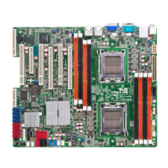
2.2.3 Motherboard layouts ASUS KCMA-D8... -
Page 26: Layout Contents
2.2.4 Layout contents Slots/Soocket Page CPU sockets 2-10 DDR3 sockets 2-18 PCI Express x16 / PCI Express x8 / PCI / MIO slots 2-23 PIKE slot 2-23 Jumpers Page Clear RTC RAM (CLRTC1) 2-27 VGA controller setting (3-pin VGA_SW1) 2-28 CPU Fan and Chassis Fan control setting 2-28 (3-pin CPUFAN_SEL1, CHAFAN_SEL1) - Page 27 BMC header (BMC_FW1) 2-37 Power Supply SMBus connector (5-pin PSUSMB1) 2-38 Location LED cable connector (3-pin LOCLED1) 2-38 24+8-pin power connectors 2-39 (24-pin ATXPWR1, 8-pin ATX12V1) System panel connector (20-1 pin PANEL1) 2-40 Auxiliary panel connector (20-2 pin AUX_PANEL1) 2-41 ASUS KCMA-D8...
-
Page 28: Central Processing Unit (Cpu)
ASUS shoulders the repair cost only if the damage is shipment/transit-related. • Keep the cap after installing the motherboard. ASUS will process Return Merchandise Authorization (RMA) requests only if the motherboard comes with the cap on the LGA 1207 Socket. - Page 29 Gold triangle mark into the CPU notch. The CPU fits in only one correct orientation. DO NOT force the CPU into the socket to prevent bending the connectors on the socket and damaging the CPU! Alignment keys ASUS KCMA-D8 2-11...
- Page 30 Close the load plate (A), then push the load lever (B) until it snaps into the retention tab. Apply some Thermal Interface Material to the exposed area of the CPU that the heatsink will be in contact with, ensuring that it is spread in an even thin layer. Some heatsinks come with pre-applied Thermal Interface Material.
-
Page 31: Installing The Retension Module Base
Place one retension module on the screw stand. Use the screw that comes with the retension module to secure the retension module to the motherboard. Repeat steps 2 to 3 to install the other retension module to the motherboard. ASUS KCMA-D8 2-13... -
Page 32: Installing The Cpu Heatsink And Fan Assembly
2.3.3 Installing the CPU heatsink and fan assembly The AMD Opteron™ 4100 series processors require a specially designed heatsink ® and fan assembly to ensure optimum thermal condition and performance. • Ensure to use qualified heatsink and fan assembly only. •... - Page 33 Push down the retention bracket lock on the retention mechanism to secure the heatsink and fan assembly to the module base. ASUS KCMA-D8 2-15...
- Page 34 When the heatsink and fan assembly is in place, connect the CPU fan cable to the connector on the motherboard labeled CPU_FAN. • Do not forget to connect the CPU fan connector! Hardware monitoring errors can occur if you fail to plug this connector. •...
-
Page 35: Installing The Cpu Heatsink
Twist each of the two screws with a Philips (cross) screwdriver just enough to attach the heatsink to the motherboard. When the two screws are attached, tighten them one by one to completely secure the heatsink. ASUS KCMA-D8 2-17... -
Page 36: System Memory
System memory 2.4.1 Overview The motherboard comes with eight (8) Double Data Rate 3 (DDR3) Dual Inline Memory Modules (DIMM) sockets. A DDR3 module has the same physical dimensions as a DDR2 DIMM but is notched differently to prevent installation on a DDR2 DIMM socket. DDR3 modules are developed for better performance with less power consumption. -
Page 37: Memory Configurations
Memory population table For UDIMM (Single Rank, Dual Ranks) & RDIMM (Single Rank, Dual Ranks & Quad Ranks) CPU1 Configuration DIMM_A2 DIMM_A1 DIMM_B2 DIMM_B1 2 DIMMs 4 DIMMs CPU2 Configuration DIMM_C2 DIMM_C1 DIMM_D2 DIMM_D1 2 DIMMs 4 DIMMs ASUS KCMA-D8 2-19... -
Page 38: Installing A Dimm
2.4.3 Installing a DIMM Unplug the power supply before adding or removing DIMMs or other system components. Failure to do so can cause severe damage to both the motherboard and the components. To install a DIMM: Press the retaining clips outward DDR3 DIMM notch to unlock a DIMM socket. -
Page 39: Expansion Slots
When using PCI cards on shared slots, ensure that the drivers support “Share IRQ” or that the cards do not need IRQ assignments. Otherwise, conflicts will arise between the two PCI groups, making the system unstable and the card inoperable. ASUS KCMA-D8 2-21... -
Page 40: Interrupt Assignments
2.5.3 Interrupt assignments Standard Interrupt assignments Priority Standard function System Timer Keyboard Controller Programmable Interrupt Communications Port (COM2) Communications Port (COM1) Floppy Disk Controller System CMOS/Real Time Clock ACPI Mode when used IRQ Holder for PCI Steering IRQ Holder for PCI Steering PS/2 Compatible Mouse Port Numeric Data Processor Primary IDE Channel... -
Page 41: Pci Express X16 Slots (X16 Link; X8 Link)
2.5.7 PIKE slot The PIKE slot allows you to choose and change your preferred SAS solution easily. Install an optional ASUS PIKE RAID card based on your needs. PCI-E x16 slot (Gen2 x16 link) PCI slot PCI-E x16 slot (Gen2 x8 link) -
Page 42: Installing An Asus Pike Raid Card
2.5.8 Installing an ASUS PIKE RAID card Follow the steps below to install an optional ASUS RAID card on your motherboard. Locate the PIKE RAID card slot on the motherboard. Align the golden fingers of the RAID card with the PIKE RAID card slot. -
Page 43: Installing I Button
You need to install I Button before using PIKE 1078 functions. 2.5.10 Installing ASMB4 management card Follow the steps below to install an optional ASMB4 management card on your motherboard. Locate the BMC_FW header on the motherboard. Orient and press the ASMB4 management card in place. ASUS KCMA-D8 2-25... -
Page 44: Connecting The Thermal Sensor Cable
2.5.11 Connecting the thermal sensor cable Follow the steps below to connect the thermal sensor cable to the connector on your motherboard. Locate the TR1 or TR2 connector on the motherboard. Connect the thermal sensor cable to the connector. Place the other end of the thermal sensor cable to the device you would like to monitor temperature. -
Page 45: Jumpers
Removing the cap will cause system boot failure! If the steps above do not help, remove the onboard battery and move the jumper again to clear the CMOS RTC RAM data. After the CMOS clearance, reinstall the battery. ASUS KCMA-D8 2-27... - Page 46 VGA controller setting (3-pin VGA_SW1) This jumper allows you to enable or disable the onboard VGA controller. Set to pins 1–2 to activate the VGA feature. CPU Fan and Chassis Fan control setting (3-pin CPUFAN_SEL1, CHAFAN_SEL1) These jumpers allow you to switch for fan pin selection. The CPUFAN_SEL1 jumper is for the CPU fans control and the CHAFAN_SEL1 jumper is for the front fans and rear fans control.
- Page 47 The slot 2 and PIKE slot share the x4 link. Place the jumper cap on pins 1–2 to let the system swtich the assignment automatically depending on which slot is occupied. Or you can place the jumper cap on pins 2–3 to assign the x4 link to the PIKE slot. ASUS KCMA-D8 2-29...
- Page 48 LAN controller setting (3-pin LAN_SW1; LAN-SW2) These jumpers allow you to enable or disable the onboard Intel Gigabit LAN ® controllers. Set to pins 1-2 to activate the Gigabit LAN feature. Force BIOS recovery setting (3-pin RECOVERY1) This jumper allows you to quickly update or recover the BIOS settings when it becomes corrupted.
-
Page 49: Connectors
LED indications. LAN port LED indications ACT/LINK SPEED Activity/Link LED Speed LED Status Description Status Description No link 10 Mbps connection GREEN Linked ORANGE 100 Mbps connection BLINKING Data activity GREEN 1 Gbps connection LAN port ASUS KCMA-D8 2-31... -
Page 50: Internal Connectors
2.7.2 Internal connectors Serial ATA connectors (7-pin SATA1, SATA2, SATA3, SATA4; RED) (7-pin SATA5, SATA6; Black) Supported by the AMD SP5100 chipset, these connectors are for the Serial ® ATA signal cables for Serial ATA hard disk drives that allows up to 3Gb/s of data transfer rate. -
Page 51: Sas Connectors
SCSI (SAS) and Serial ATA (SATA). Each connector supports one device. • These connectors function only when you install a PIKE RAID card. • Connect the SAS hard disk drives to SAS connectors 1–4 (red) when installing a 4-port PIKE RAID card. ASUS KCMA-D8 2-33... - Page 52 USB connector (10-1 pin USB34, USB56; A-Type USB7) These connectors are for USB 2.0 ports. Connect the USB module cables to connectors USB34 and USB56, then install the modules to a slot opening at the back of the system chassis. These USB connectors comply with USB 2.0 specification that supports up to 480 Mbps connection speed.
- Page 53 DO NOT forget to connect the fan cables to the fan connectors. Insufficient air flow inside the system may damage the motherboard components. • These are not jumpers! DO NOT place jumper caps on the fan connectors! • All fans feature the ASUS Fan Speed technology. ASUS KCMA-D8 2-35...
- Page 54 These connectors are used for the SAS chip SGPIO interface that controls the LED pattern generation, device information and general purpose data. These connectors function only when you install an ASUS PIKE SAS RAID card. Serial General Purpose Input/Output connector (8-1 pin SGPIO3/4) These connectors are used for the SGPIO peripherals of the PROMISE ®...
- Page 55 The serial port module is purchased separately. BMC header (BMC_FW1) The BMC connector on the motherboard supports an ASUS ® Server Management Board 4 Series (ASMB4).
- Page 56 PSU information. Devices communicate with an SMBus host and/or other SMBus devices using the SMBus interface. This connector functions only when you install the ASUS ASMB4. 11. Location LED cable connector (3-pin LOCLED1) This connector is for a LED cable that allows you to know the server location.
- Page 57 The system may become unstable or may not boot up if the power is inadequate. • Ensure that your power supply unit (PSU) can provide at least the minimum power required by your system (450W or above; 12V1 > 18A). ASUS KCMA-D8 2-39...
-
Page 58: System Panel Connector
13. System panel connector (20-pin PANEL1) This connector supports several chassis-mounted functions. System power LED (3-pin PLED) This 3-pin connector is for the system power LED. Connect the chassis power LED cable to this connector. The system power LED lights up when you turn on the system power, and blinks when the system is in sleep mode. - Page 59 Connect the Locator LED cables to these 2-pin connector. The LEDs will light up when the Locator button is pressed. Locator Button/Swich (2-pin LOCATORBTN) These leads are for the locator button on the front panel. This button queries the state of the system locator. ASUS KCMA-D8 2-41...
- Page 60 2-42 Chapter 2: Hardware information...
-
Page 61: Chapter 3: Powering Up
This chapter describes the power up sequence, and ways of shutting down the system. Powering up Chapter 3:... - Page 62 Chapter summary Starting up for the first time ............3-3 Powering off the computer ............3-4 ASUS KCMA-D8...
-
Page 63: Starting Up For The First Time
Check the jumper settings and connections or call your retailer for assistance. At power on, hold down the <Del> key to enter the BIOS Setup. Follow the instructions in Chapter 4. ASUS KCMA-D8... -
Page 64: Powering Off The Computer
Powering off the computer 3.2.1 Using the OS shut down function If you are using Windows 2003 Server: ® Click the Start button then click Shut Down. Select Shut Down from the What do you want the computer to do? list box. -
Page 65: Chapter 4: Bios Setup
This chapter tells how to change the system settings through the BIOS Setup menus. Detailed descriptions of the BIOS parameters are also provided. BIOS setup Chapter 4:... - Page 66 Managing and updating your BIOS ..........4-3 BIOS setup program ..............4-7 Main menu .................. 4-10 Advanced menu ................. 4-15 Server menu ................4-30 Power menu ................4-32 Boot menu .................. 4-36 Tools menu ................. 4-40 Exit menu ..................4-41 ASUS KCMA-D8...
-
Page 67: Managing And Updating Your Bios
BIOS using the ASUS Update or AFUDOS utilities. 4.1.1 ASUS EZ Flash 2 utility The ASUS EZ Flash 2 feature allows you to update the BIOS without having to use a DOS-based utility. Before you start using this utility, download the latest BIOS from the ASUS website at www.asus.com. -
Page 68: Bupdater Utility
Updating the BIOS file To update the BIOS file using the BUPDATER utility: Visit the ASUS website at www.asus.com and download the latest BIOS file for the motherboard. Save the BIOS file to a bootable USB flash disk drive. Copy the BUPDATER utility (BUPDATER.exe) from the ASUS support website at support.asus.com to the bootable USB flash disk drive you created... - Page 69 DO NOT shut down or reset the system while updating the BIOS to prevent system boot failure! The utility returns to the DOS prompt after the BIOS update process is completed. Reboot the system from the hard disk drive. The BIOS update is finished! Please restart your system. C:\> ASUS KCMA-D8...
-
Page 70: Asus Crashfree Bios 3 Utility
4.1.3 ASUS CrashFree BIOS 3 utility The ASUS CrashFree BIOS 3 is an auto recovery tool that allows you to restore the BIOS file when it fails or gets corrupted during the updating process. You can update a corrupted BIOS file using a USB flash drive that contains the updated BIOS file. -
Page 71: Bios Setup Program
The BIOS setup screens shown in this section are for reference purposes only, and may not exactly match what you see on your screen. • Visit the ASUS website (www.asus.com) to download the latest BIOS file for this motherboard. ASUS KCMA-D8... -
Page 72: Bios Menu Screen
4.2.1 BIOS menu screen Menu items Menu bar Configuration fields General help BIOS SETUP UTILITY Main Advanced Server Power Boot Tools Exit Use [ENTER], [TAB] System Time [13:44:30] or [SHIFT-TAB] to System Date [Wed 08/18/2010] select a field. SATA 1 [ST3160812AS] Use [+] or [-] to SATA 2... -
Page 73: Menu Items
<Page Up> /<Page Down> keys to display the other items on the screen. Pop-up window Scroll bar 4.2.9 General help At the top right corner of the menu screen is a brief description of the selected item. ASUS KCMA-D8... -
Page 74: Main Menu
Main menu When you enter the BIOS Setup program, the Main menu screen appears, giving you an overview of the basic system information. Refer to section 4.2.1 BIOS menu screen for information on the menu screen items and how to navigate through them. BIOS SETUP UTILITY Main Advanced... -
Page 75: Sata1-6
When set to [Disabled], the data transfer from and to the device occurs one sector at a time. Configuration options: [Disabled] [Auto] ASUS KCMA-D8 4-11... -
Page 76: Storage Configuration
PIO Mode [Auto] Allows you to select the data transfer mode. Configuration options: [Auto] [0] [1] [2] [3] [4] DMA Mode [Auto] DMA (Direct Memory Access) allows your computer to transfer data to and from the hardware devices installed with much less CPU overhead. The DMA mode consists of SWDMA (single-word DMA), MWDMA (multi-word DMA), and UDMA (Ultra DMA). - Page 77 SATA connectors 5 or 6 when installing OS. If you use a SATA optical drive to run the OS installation disk, we strongly recommend that you install the optical dirve to the SATA connectors 5/6 and set them to [IDE] mode. ASUS KCMA-D8 4-13...
-
Page 78: System Information
4.3.5 System Information This menu gives you an overview of the general system specifications. The BIOS automatically detects the items in this menu. BIOS SETUP UTILITY Main BIOS Information Version :0201 Build Date :08/06/10 Processor Type :AMD Opteron(tm) Processor 4170 HE Speed :2100MHZ System Memory... -
Page 79: Advanced Menu
PowerNow [Enabled] Exit PowerCap [P-state 0] ACPI SRAT Table [Enabled] v02.61 (C)Copyright 1985-2010, American Megatrends, Inc. Scroll down for more items. CPU DownCore Mode [Auto Mode] C1E Support [Enabled] CPU2 [Enabled] v02.61 (C)Copyright 1985-2010, American Megatrends, Inc. ASUS KCMA-D8 4-15... - Page 80 GART Error Reporting [Disabled] This option should remain disabled for the normal operation. The driver developer may enable it for testing purpose. Configuration options: [Disabled] [Enabled] Microcode Updation [Enabled] Allows the system to update the Microcode automatically, enhancing system performance. Configuration options: [Disabled] [Enabled] Secure Virtual Machine Mode [Enabled] Allows you to enable or disable the AMD Secure Virtual Machine.
-
Page 81: Chipset Configuration
RAS/RAS Delay(Trrd) :N/A, 4 CLK Enter Go to Sub Screen Row Cycle (Trc) :N/A, 33 CLK General Help Read to Precharge(Trtp):N/A, 5 CLK Save and Exit Write Recover Time(Twr):N/A, 10 CLK Exit v02.61 (C)Copyright 1985-2010, American Megatrends, Inc. ASUS KCMA-D8 4-17... -
Page 82: Memory Configuration
Memory Configuration The memory configuration menu allows you to change the memory settings. BIOS SETUP UTILITY Advanced Memory Configuration Enable Bank Memory Interleaving Bank Interleaving [Auto] Node Interleaving [Disabled] Channel Interleaving [Auto] CS Sparing Enable [Disabled] Bank Swizzle Mode [Enabled] Channel B [Enabled] Channel C... -
Page 83: Ecc Configuration
Allows you to select the DRAM timing mode. Configuration options: [Auto] [Manual] Memory Clock Speed [400 MHz] This item appears only when you set the DRAM Timing Config item to [Manual] and allows you to set the memory clock frequency. Configuration options: [400 MHz] [533 MHz] [667 MHz] ASUS KCMA-D8 4-19... -
Page 84: Southbridge Configuration
SouthBridge Configuration BIOS SETUP UTILITY Advanced SouthBridge Chipset Configuration Options for SB HD Azalia SP5100 CIMx Version : 5.5.0 SB Azalia Audio Configuration SB Debug Configuration OHCI HC (Bus 0 Dev 18 Fn 0) [Enabled] OHCI HC (Bus 0 Dev 18 Fn 1) [Enabled] EHCI HC (Bus 0 Dev 18 Fn 2) [Enabled]... - Page 85 When set to [Enabled], the system will turn off the clocks for the unused SATA ports in IDE modes. Doing so will enable some power savings. Configuration options: [Disabled] [Enabled] The hot-plug function will be disabled when turning off the clock for the SATA port. ASUS KCMA-D8 4-21...
- Page 86 SATA-AHCI Ports Auto Clk Ctrl [Disabled] When set to [Enabled], the system will turn off the clocks for the unused SATA ports in AHCI modes. Doing so will enable some power savings. Configuration options: [Disabled] [Enabled] The hot-plug function will be disabled when turning off the clock for the SATA port.
-
Page 87: Pci Express Configuration
Configuration options: [Auto] [Disabled] [Software Initiated] [Advertised RC] Link ASPM [Disabled] Configuration options: [Disabled] [L0s] [L1] [L0s & L1] [L0s Downstream] [L0s Downstream + L1] Compliance Mode [Disabled] Configuration options: [Disabled] [Enabled] Lane Reversal [Disabled] Configuration options: [Disabled] [Enabled] ASUS KCMA-D8 4-23... - Page 88 NB-SB Port Features Press <Enter> to display the sub-items. NB-SB Link ASPM [L1] Configuration options: [Disabled] [L1] NP NB-SB VC1 Traffic Support [Disabled] Configuration options: [Disabled] [Enabled] Complicance Mode [Disabled] Configuration options: [Disabled] [Enabled] PCIE Slot 1, PCIE Slot 3, PIKE Slot/PCIE Slot 5, SB Core Setting Select an item, and then press <Enter>...
-
Page 89: Hyper Transport Configuration
NB Deempasies Level [Disabled] Configuration options: [Disabled] [-0.4dB] [-1.32dB] [-2.08dB] [-3.1dB] [-4.22dB] [-5.50dB] [-7.05dB] IOMMU [Disabled] Configuration options: [Disabled] [Enabled] Primary Video Controller [Slot1-Slot3-PIKE/Slot5-PCI] Allows you to select the primary video controller. Configuration options: [Slot1-Slot3-PIKE/Slot5-PCI] [Slot3-Slot1-PIKE/Slot5-PCI] [PIKE/Slot5-Slot1-Slot3-PCI] [PCI-Slot1-Slot3-PIKE/Slot5] ASUS KCMA-D8 4-25... - Page 90 Debug Option Advanced Memory Decode on Sec. GFX [Disabled] Options IOC Peer-to-Peer Mode [Auto] Northbridge interrupt pin [Disabled] Disabled Force Select Screen ←→ Select Item ↑↓ Change Option General Help Save and Exit Exit v02.61 (C)Copyright 1985-2010, American Megatrends, Inc. Memory Decode on Sec.
-
Page 91: Onboard Devices Configuration
Enables or disables the onboard LAN1/2 controller. Configuration options: [Disabled] [Enabled] The following items appear only when you set Onboard LAN1/LAN2 Chip to [Enabled]. Onboard LAN1/LAN2 Boot [PXE] Allows you to configure the onboard LAN1/2 boot mode. Configuration options: [Disabled] [PXE] [iSCSI] ASUS KCMA-D8 4-27... -
Page 92: Usb Configuration
4.4.4 USB Configuration BIOS SETUP UTILITY Advanced USB Configuration Enables support for legacy USB. AUTO Module Version - 2.24.5-13.4 option disables legacy support if USB Devices Enabled : no USB devices are None connected. Legacy USB Support [Enabled] USB 2.0 Controller Mode [HiSpeed] BIOS EHCI Hand-Off [Enabled]... -
Page 93: Pcipnp
View all unread events on the Event Log. View Event Log Clear Event Log View Event Log Press <Enter> to read all the unread event log. Clear Event Log Press <Enter> to clear all events on the event log. ASUS KCMA-D8 4-29... -
Page 94: Server Menu
Server menu BIOS SETUP UTILITY Main Advanced Server Power Boot Tools Exit Configure Remote Access. Remote Access Configuration Select Screen ←→ Select Item ↑↓ Enter Go to Sub Screen General Help Save and Exit Exit v02.61 (C)Copyright 1985-2010, American Megatrends, Inc. Remote Access Configuration The items in this menu allows you to configure the Remote Access features. - Page 95 Sets the redirection mode after the BIOS Power-On Self-Test (POST). Some operating systems may not work when set to [Always]. Configuration options: [Disabled] [Boot Loader] [Always] Terminal Type [VT-UTF8] Allows you to select the target terminal type. Configuration options: [ANSI] [VT100] [VT-UTF8] ASUS KCMA-D8 4-31...
-
Page 96: Power Menu
Power menu The Power menu items allow you to change the settings for the Advanced Power Management (APM). Select an item then press <Enter> to display the configuration options. BIOS SETUP UTILITY Main Advanced Server Power Boot Tools Exit Select the ACPI state used for System Suspend Mode [Auto]... -
Page 97: Apm Configuration
To set the alarm date, highlight this item and press the <+> or <-> key to make the selection. System Time [12:30:30] Use the <ENTER>, <TAB> or <SHIFT-TAB> key to select a field. Use the <+> or <-> key to configure alarm time. ASUS KCMA-D8 4-33... -
Page 98: Hardware Monitor
4.6.6 Hardware Monitor BIOS SETUP UTILITY Power Hardware Monitor CPU1 Temperature CPU1 Temperature [ 38 ºC/ 100 ºF] CPU2 Temperature TR1 Temperature TR2 Temperature CPU Fan1 Speed [ 1844 RPM] CPU Fan2 Speed Front Fan1 Speed Front Fan2 Speed Front Fan3 Speed Front Fan4 Speed Front Fan5 Speed Rear Fan1 Speed... - Page 99 Fan Speed Control [Generic Mode] Allows you to configure the ASUS Smart Fan feature that smartly adjusts the fan speeds for more efficient system operation. Configuration options: [Full Speed Mode] [Whisper Mode] [Generic Mode] [High Density Mode] VCORE1/2 Voltage, P1/2DDR3 Voltage, P1/2_+1.2V Voltage, P1_VDDNB Voltage, +1.8V Voltage, +1.2V Voltage, +1.1V Voltage,...
-
Page 100: Boot Menu
Boot menu The Boot menu items allow you to change the system boot options. Select an item then press <Enter> to display the submenu. BIOS SETUP UTILITY Main Advanced Server Power Boot Tools Exit Specifies the Boot Boot Settings Device Priority Boot Device Priority sequence. -
Page 101: Boot Settings Configuration
Allows you to enable or disable the full screen logo display feature. Configuration options: [Disabled] [Enabled] Set this item to [Enabled] to use the ASUS MyLogo2™ feature. AddOn ROM Display Mode [Force BIOS] Allows you to set the display mode for Options ROM. -
Page 102: Security
4.7.4 Security The Security menu items allow you to change the system security settings. Select an item then press <Enter> to display the configuration options. BIOS SETUP UTILITY Boot Security Settings <Enter> to change password. <Enter> again to Supervisor Password : Not Installed disable password. -
Page 103: Change User Password
Password Check [Setup] When set to [Setup], BIOS checks for user password when accessing the Setup utility. When set to [Always], BIOS checks for user password both when accessing Setup and booting the system. Configuration options: [Setup] [Always] ASUS KCMA-D8 4-39... -
Page 104: Tools Menu
(C)Copyright 1985-2009, American Megatrends, Inc. ASUS EZ Flash 2 Allows you to run ASUS EZ Flash 2. When you press <Enter>, a confirmation message appears. Use the left/right arrow key to select between [Yes] or [No], then press <Enter> to confirm your choice. Check section 4.1.1 ASUS EZ Flash 2 utility for details. -
Page 105: Exit Menu
Setup menus. When you select this option or if you press <F5>, a confirmation window appears. Select YES to load default values. Select Exit & Save Changes or make other changes before saving the values to the non-volatile RAM. ASUS KCMA-D8 4-41... - Page 106 4-42 Chapter 4: BIOS setup...
- Page 107 This chapter provides instructions for setting up, creating, and configuring RAID sets using the available utilities. RAID configuration...
- Page 108 Chapter summary Setting up RAID ................5-3 FastBuild Utility ................5-5 ASUS KCMA-D8...
-
Page 109: Setting Up Raid
If you want to boot the system from a hard disk drive included in a created RAID set, copy first the RAID driver from the support CD to a floppy disk before you install an operating system to the selected hard disk drive. ASUS KCMA-D8... -
Page 110: Installing Hard Disk Drives
5.1.2 Installing hard disk drives The motherboard supports Serial ATA for RAID set configuration. For optimal performance, install identical drives of the same model and capacity when creating a disk array. To install the SATA hard disks for RAID configuration: Install the SATA hard disks into the drive bays following the instructions in the system user guide. -
Page 111: Fastbuild Utility
Controller Configuration ..[ 4 ] [ Keys Available ] Press 1..4 to Select Option [ESC]Exit The RAID BIOS setup screens shown in this section are for reference only and may not exactly match the items on your screen. ASUS KCMA-D8... -
Page 112: Creating A Raid Set (Raid 0, Raid 1, Raid 10 Raid 5, Span Or Jbod)
5.2.1 Creating a RAID set (RAID 0, RAID 1, RAID 10, RAID 5, SPAN or JBOD) To create a RAID set: From the main control panel, press <2> to to enter the LD View Menu. FastBuild (tm) Utility (c) 2004-2010 Promise Technology, Inc. [ Main Menu ] View Drive Assignment ..[ 1 ] LD View / LD Define Menu ..[ 2 ]... - Page 113 SATA 3G 250.05 02:01 HDTXXXXXXXXXXXX SATA 3G 250.05 03:01 HDTXXXXXXXXXXXX SATA 3G 250.05 04:01 HDTXXXXXXXXXXXX SATA 3G 250.05 [ Keys Available ] ] Up [ ] Down [PaUp/PaDn] Switch Page [Space] Change Option ↑ ↓ [Ctrl+Y] Save [ESC] Exit ASUS KCMA-D8...
- Page 114 After you have selected the desired RAID mode, use the down arrow key to select desired disks for the RAID set. FastBuild (tm) Utility (c) 2004-2010 Promise Technology, Inc. [ LD Define Menu ] LD No LD Name RAID Mode Logical Drive 1 RAID 1 Stripe Block...
- Page 115 HDTXXXXXXXXXXXX SATA 3G 250.05 <Press any other key to ignore this option> 04:01 HDTXXXXXXXXXXXX SATA 3G 250.05 [ Keys Available ] ] Up [ ] Down [PaUp/PaDn] Switch Page [Space] Change Option ↑ ↓ [Ctrl+Y] Save [ESC] Exit ASUS KCMA-D8...
- Page 116 Press <Ctrl> + <Y> to modify the disk array size or press any other key to use all the available capacity of the disk drive. FastBuild (tm) Utility (c) 2004-2010 Promise Technology, Inc. [ LD Define Menu ] LD No LD Name RAID Mode Logical Drive 1...
- Page 117 Capacity(GB) RAID1 RAID 1 199.99 Stripe Block Read Policy Read Cache Write Policy WriteBack [ Drives Assignments ] Port:ID Drive Model Capabilities Capacity(GB) 01:01 HDTXXXXXXXXXXXX SATA 3G 250.05 02:01 HDTXXXXXXXXXXXX SATA 3G 250.05 Any Key To Continue..ASUS KCMA-D8 5-11...
-
Page 118: Deleting A Raid Set
5.2.2 Deleting a RAID set To delete a RAID set: From the main control panel, press <3> to to enter the Delete LD Menu. FastBuild (tm) Utility (c) 2004-2010 Promise Technology, Inc. [ Main Menu ] View Drive Assignment ..[ 1 ] LD View / LD Define Menu ..[ 2 ] Delete LD Menu ....[ 3 ] Controller Configuration ..[ 4 ]... - Page 119 FastBuild (tm) Utility (c) 2004-2010 Promise Technology, Inc. [ Delete LD Menu ] < There is no any LD > [ Keys Available ] ] Up [ ] Down [PaUp/PaDn] Switch Page [Del/Alt+D] Delete LD ↑ ↓ [Ctrl+V] View JBOD Disk [ESC] Exit ASUS KCMA-D8 5-13...
-
Page 120: Viewing The Drive Assignment
5.2.3 Viewing the Drive Assignment To view the drive assignment: From the main control panel, press <1> to to enter the Drive Assignment Menu. FastBuild (tm) Utility (c) 2004-2010 Promise Technology, Inc. [ Main Menu ] View Drive Assignment ..[ 1 ] LD View / LD Define Menu ..[ 2 ] Delete LD Menu ....[ 3 ] Controller Configuration ..[ 4 ]... -
Page 121: Viewing The Controller Configuration
FastBuild (tm) Utility (c) 2004-2010 Promise Technology, Inc. [ Adapter Configuration - Options ] No Parameters Defined for Current Disk(s)... [ System Resources Configuration ] Controller IRQ: 10 AHCI HBA MMIO Base Address: FAFFE400 [ Keys Available ] [ESC] Exit ASUS KCMA-D8 5-15... - Page 122 5-16 Chapter 5: RAID configuration...
-
Page 123: Chapter 6: Driver Installation
This chapter provides instructions for installing the necessary drivers for different system components. Driver Chapter 6: installation... - Page 124 Chapter summary RAID driver installation ............... 6-3 processor driver installation .......... 6-15 ® LAN driver installation ............... 6-16 ATI SM Bus controller driver installation ......... 6-20 Display driver installation ............6-21 Management application and utilities installation ....6-24 ASUS KCMA-D8...
-
Page 125: Raid Driver Installation
Save your changes, then exit the BIOS Setup. Restart the computer. The Makedisk menu appears.Select Promise SW ROMB Controller Driver, and press <Enter> to enter the submenu. Create Driver Diskette Menu Promise SW ROMB Controller Driver AMD AHCI Controller Driver Write DMI FreeDOS command prompt ASUS KCMA-D8... - Page 126 Use the arrow keys to select the type of RAID driver disk you want to create. Promise SW ROMB Controller Driver Windows Server 2003 32/64 bit Windows Server 2008 32 bit Windows Server 2008 64 bit Windows Server 2008 R2 64 bit RHEL AS4 UP8 32 bit RHEL AS4 UP8 64 bit RHEL 5 UP4 32 bit...
-
Page 127: Installing The Raid Controller Driver
S. * If you do not have any device support disks from a mass storage device manufacturer, or do not want to specify additional mass storage devices for use with Windows, press ENTER. S=Specify Additional Device ENTER=Continue F3=Exit ASUS KCMA-D8... - Page 128 Insert the RAID driver disk you created earlier to the floppy disk drive, then press <Enter>. Windows Setup Please insert the disk labeled Manufacturer-supplied hardware support disk into Drive A: Press ENTER when ready. ENTER=Continue ESC=Cancel F3=Exit Select the RAID controller driver you need from the list, then press <Enter>. The Windows Setup loads the RAID controller drivers from the RAID driver ®...
- Page 129 The screen differs based on the controller. Right-click the RAID controller driver item, and then select Properties from the menu. Click the Driver tab, and then click the Driver Details button to display the RAID controller drivers. Click OK when finished. ASUS KCMA-D8...
- Page 130 Red Hat Enterprise Linux OS 4.7/4.8 ® To install the RAID controller driver when installing Red Hat Enterprise OS: ® Boot the system from the Red Hat OS installation CD. ® At the boot:, type linux dd. Press <Enter>. - To install or upgrade in graphical mode, press the <ENTER> key. - To install or upgrade in text mode, type: linux text <ENTER>.
- Page 131 Select Skip and press <Enter> to continue. CD Found To begin testing the CD media before installation press OK. Choose Skip to skip the media test and start the installation. Skip Follow the onscreen instructions to finish installing the RedHat operating system. ASUS KCMA-D8...
- Page 132 Red Hat Enterprise Linux OS 5.0 ® To install the RAID controller driver when installing Red Hat Enterprise OS: ® Boot the system from the Red Hat OS installation CD. ® At the boot:, type linux dd Press <Enter>. - To install or upgrade in graphical mode, press the <ENTER> key. - To install or upgrade in text mode, type: linux text <ENTER>.
- Page 133 When asked if you will load additional RAID controller drivers, select No, then press <Enter>. More Driver Disks? Do you wish to load any more driver disks? Follow the onscreen instructions to finish the OS installation. ASUS KCMA-D8 6-11...
- Page 134 SUSE Linux 11 OS To install the RAID controller driver when installing SUSE Linux Enterprise Server Boot the system from the SUSE OS installation CD. Use the arrow keys to select Installation from the Boot Options menu. Boot from Hard Disk Installation Repair Installed System Rescue System...
- Page 135 English(US) 1024 X768 Default When below screen appears, select the USB floppy disk drive (sda) as the driver update medium. Select OK, then press <Enter>. Please choose the Driver Update medium. sda: USB Floppy Other device Back ASUS KCMA-D8 6-13...
- Page 136 The drivers for the RAID controller are installed to the system as shown below. Please choose the Driver Update medium. sda: USB Floppy sr0: CD-ROM, ASUS DRW-1612BLT sdb: Disk, Promise 1X2 Morror/RAID1 sd3: Disk, Promise RAID Console other device Back Select Back and follow the onscreen instructions to finish the installation.
-
Page 137: Amd ® Processor Driver Installation
If Autorun is NOT enabled in your computer, browse the contents of the support DVD to locate the file AUTORUN.EXE and double-click the AUTORUN.EXE to run the support DVD. Click the item AMD Processor Driver from the menu, and then follow the onscreen instructions to complete the installation. ASUS KCMA-D8 6-15... -
Page 138: Lan Driver Installation
LAN driver installation This section provides the instructions on how to install Intel Gigabit LAN controller ® driver. To install the Intel Gigabit LAN controller driver on a Windows ® ® Restart the computer, and then log on with Administrator privileges. Insert the motherboard/system support DVD to the optical drive. - Page 139 When the Intel Network Connections – InstallShield Wizard window ® appears, click Next to start the installation. Click I accept the terms in the license agreement and then click Next to continue. ASUS KCMA-D8 6-17...
- Page 140 Select the programs you want to install and click Next to continue. Click Install to start the installation. 6-18 Chapter 6: Driver installation...
- Page 141 The programs you select are being installed. Click Finish to finish the installation. ASUS KCMA-D8 6-19...
-
Page 142: Ati Sm Bus Controller Driver Installation
ATI SM Bus controller driver installation This section provides instructions on how to install the ATI SM Bus driver on the system. You need to manually install the ATI SMBus driver on a Windows ® XP / Server 2003 operating system. To install the driver: Restart the computer, then log on with Administrator privileges. -
Page 143: Display Driver Installation
DVD automatically displays the Drivers menu if Autorun is enabled in your computer. If Autorun is NOT enabled in your computer, browse the contents of the support DVD to locate the file AUTORUN.EXE and double-click the AUTORUN.EXE to run the support DVD. Click ASPEED AST2050 Display Driver. ASUS KCMA-D8 6-21... - Page 144 When the ASPEED InstallShield Wizard window appears, click Next to continue. Click Install to start the installation. 6-22 Chapter 6: Driver installation...
- Page 145 The system installs the driver automatically. When the installation completes, click Finish to exit the wizard. ASUS KCMA-D8 6-23...
-
Page 146: Management Applications And Utilities Installation
The contents of the support DVD are subject to change at any time without notice. Visit the ASUS website (www.asus.com) for updates. 6.6.1 Running the support DVD Place the support DVD to the optical drive. -
Page 147: Utilities Menu
The Make disk menu contains items to create the AMD AHCI driver disk. 6.6.5 Contact information Click the Contact tab to display the ASUS contact information. You can also find this information on the inside front cover of this user guide. ASUS KCMA-D8 6-25... - Page 148 6-26 Chapter 6: Driver installation...
-
Page 149: Appendix: Reference Information
This appendix includes additional information that you may refer to when configuring the motherboard. Reference information Appendix:... -
Page 150: A.1 Kcma-D8 Block Diagram
Appendix summary KCMA-D8 block diagram .............A-3 ASUS KCMA-D8... -
Page 151: Kcma-D8 Block Diagram
KCMA-D8 block diagram ASUS KCMA-D8... - Page 152 Appendix A: Reference information...