Table of Contents
Advertisement
Advertisement
Table of Contents

Related Manuals for Asus K8S-MX


Summary of Contents for Asus K8S-MX
- Page 1 K8S-MX User Guide...
- Page 2 Product warranty or service will not be extended if: (1) the product is repaired, modified or altered, unless such repair, modification of alteration is authorized in writing by ASUS; or (2) the serial number of the product is defaced or missing.
-
Page 3: Table Of Contents
Safety information ................. vii About this guide ................viii Conventions used in this guide ........... viii Typography ................viii K8S-MX specifications summary ............ ix Chapter 1: Product introduction 1.1 Welcome! ................1-2 1.2 Package contents ............... 1-2 1.3 Special features ..............1-3 1.3.1... - Page 4 Using AFUDOS to update the BIOS ...... 2-3 2.1.3 Using AFUDOS to copy BIOS from PC ....2-4 2.1.4 Using ASUS EZ Flash to update the BIOS .... 2-5 2.1.5 Recovering the BIOS with CrashFree BIOS 2 ..2-6 2.2 BIOS Setup program ............2-8 2.2.1...
- Page 5 Drivers menu ............3-3 3.2.3 Utilities menu ............3-3 3.2.4 Manuals ..............3-5 3.2.5 ASUS Contact Information ........3-5 3.3 RAID configurations ............3-6 3.3.1 Installing hard disks ..........3-6 3.3.2 SIS RAID configurations ........3-7 3.4 Creating a RAID driver disk ..........3-16...
-
Page 6: Notices
1. ASUS Websites The ASUS website provides updated information on ASUS hardware and software products. The ASUS websites are listed in the ASUS Contact Information on the inside front cover. 2. Optional Documentation Your product package may include optional documentation, such as warranty flyers, that may have been added by your dealer. -
Page 7: Safety Information
Safety information Electrical safety • To prevent electrical shock hazard, disconnect the power cable from the electrical outlet before relocating the system. • When adding or removing devices to or from the system, ensure that the power cables for the devices are unplugged before the signal cables are connected. If possible, disconnect all power cables from the existing system before you add a device. -
Page 8: About This Guide
About this guide Conventions used in this guide To make sure that you perform certain tasks properly, take note of the following symbols used throughout this manual. WARNING: Information to prevent injury to yourself when trying to complete a task. CAUTION: Information to prevent damage to the components when trying to complete a task. -
Page 9: K8S-Mx Specifications Summary
Features SFS (Stepless Frequency Selection) from 200 MHz up to 250 MHz at 1 MHz increment Adjustable FSB/DDR ratio ASUS JumperFree ASUS C.P.R. (CPU Parameter Recall) Special features ASUS EZ Flash ASUS CrashFree BIOS2 ASUS MyLogo™ AMD Cool ‘n’ Quiet! Technology... - Page 10 CD/AUX connectors S/PDIF out connector GAME/MIDI connector Front panel audio connector 4Mb Flash EEPROM BIOS features AMI BIOS with enhanced ACPI, PnP, DMI, ASUS MyLogo™, SM BIOS 2.3 PCI 2.2, USB 2.0/1.1 Industry standard Wake-On-LAN by PME, Wake-On-Ring by PME Manageability...
-
Page 11: Chapter 1: Product Introduction
Chapter 1 This chapter describes the features of the motherboard. It includes brief descriptions of the motherboard components, and illustrations of the layout, jumper settings, and connectors. Product introduction... -
Page 12: Welcome
K8S-MX motherboard! The motherboard delivers a host of new features and latest technologies making it another standout in the long line of ASUS quality motherboards! The motherboard combines the powers of the AMD Athlon™ 64 or AMD Sempron™ processor and the SiS 760GX chipset to set a new benchmark for an effective desktop platform solution. -
Page 13: Special Features
RAID cards. The onboard SIS 965L RAID controller provides two Serial ATA connectors for RAID 0 and RAID 1 functions. AGP 8X support AGP 8X (AGP 3.0) is the VGA interface specification that enables enhanced graphics performance with maximum bandwidth speeds of up to 2.12 GB/s. ASUS K8S-MX motherboard... -
Page 14: Unique Asus Features
1.3.2 Unique ASUS features CrashFree BIOS 2 This feature allows you to restore the original BIOS data from the ASUS support CD in case when the BIOS codes and data are corrupted. This protection eliminates the need to buy a replacement ROM chip. See page 2-6. -
Page 15: Before You Proceed
The illustration below shows the location of the onboard LED. ® SB_PWR K8S-MX Standby Powered Power K8S-MX Onboard LED ASUS K8S-MX motherboard... -
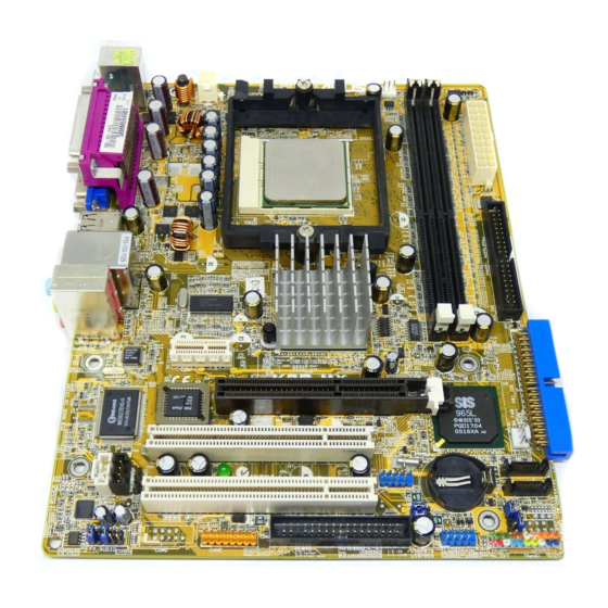
Page 16: Motherboard Overview
ATX12V COM1 USB12 USBPW34 USBPW12 Bottom: Top: USB34 RJ-45 760GX Top:Line In Center:Line Out Below:Mic In RTL8201CL PCIEX1_1 K8S-MX Accelerated Graphics Port (AGP) BIOS 965L PCI1 SATA2 SB_PWR CR2032 3V SPDIF_OUT Lithium Cell SATA1 CMOS Power USB78 PCI2 AD1888 USBPW78... -
Page 17: Placement Direction
Place six (6) screws into the holes indicated by circles to secure the motherboard to the chassis. Do not overtighten the screws! Doing so may damage the motherboard. Place this side towards the rear of the chassis K8S-MX ASUS K8S-MX motherboard... -
Page 18: Central Processing Unit (Cpu)
The 128-bit-wide data paths of these processors can run applications faster than processors with only 32-bit or 64-bit wide data paths. ® K8S-MX Gold Arrow K8S-MX CPU Socket 754 Incorrect installation of the CPU into the socket may bend the pins and severely damage the CPU! Chapter 1: Product introduction... -
Page 19: Installing The Cpu
5. When the CPU is in place, push down the socket lever to secure the CPU. The lever clicks on the side tab to indicate that it is locked. 6. Install specifically designed heatsink and fan assembly. ASUS K8S-MX motherboard... -
Page 20: System Memory
The following figure illustrates the location of the DDR DIMM sockets. ® K8S-MX K8S-MX 184-pin DDR DIMM sockets • Make sure to unplug the power supply before adding or removing DIMMs or other system components. Failure to do so may cause severe damage to both the motherboard and the components. - Page 21 Winbond W942508CH-5 • • 256MB Elpida U24256AD1PG6H20 Elpida DD2508AKTA-5C • 512MB Elpida U24512AD1PG6H20 Elpida DD2508AMTA • • 256MB Transcend DDR400-256 SAMSUNG K4H560838F-TCCC • • 256MB Transcend DDR400-256 Mosel V58C2256804SAT5B • • (Continued on the next page) ASUS K8S-MX motherboard 1-11...
- Page 22 A - supports one module inserted into either slot, in a Single-channel memory configuration. B - supports one pair of modules inserted into both slots. SS - Single-sided DS - Double-sided Visit the ASUS website (www.asus.com) for the latest DDR 400 Qualified Vendor List for this motherboard. 1-12 Chapter 1: Product introduction...
-
Page 23: Installing A Dimm
IRQ holder for PCI steering IRQ holder for PCI steering IRQ holder for PCI steering PS/2 Compatible Mouse Port Numeric Data Processor Primary IDE Channel Secondary IDE Channel These IRQs are usually available for ISA or PCI devices. ASUS K8S-MX motherboard 1-13... -
Page 24: Irq Assignments For This Motherboard
1.8.2 IRQ assignments for this motherboard INT A INT B INT C INT D PCI slot 1 shared — — — PCI slot 2 — shared — — — — — shared AGP slot — — shared — VGA slot —... -
Page 25: Agp Slot
Install only +1.5V AGP cards. ® K8S-MX Keyed for 1.5v K8S-MX Accelerated Graphics Port (AGP) If installing the ATi 9500 or 9700 Pro Series VGA cards, use only the card version PN xxx-xxxxx-30 or later, for optimum performance and overclocking stability. -
Page 26: Jumpers
Normal Clear CMOS (Default) K8S-MX Clear RTC RAM Setting You do not need to clear the RTC when the system hangs due to overclocking. For system failure due to overclocking, use the C.P.R. (CPU Parameter Recall) feature. Shut down and reboot the system so BIOS can automatically reset parameter settings to its previous values. - Page 27 +5VSB (Default) USBPW78 USBPW56 K8S-MX +5VSB K8S-MX USB device wake-up (Default) • The USB device wake-up feature requires a power supply that can provide 500mA on the +5VSB lead for each USB port. Otherwise, the system would not power up.
-
Page 28: Connectors
1.10 Connectors This section describes and illustrates the motherboard rear panel and internal connectors. 1.10.1 Rear panel connectors 1. PS/2 mouse port. This green 6-pin connector is for a PS/2 mouse. 2. Parallel port. This 25-pin port connects a parallel printer, a scanner, or other devices. -
Page 29: Internal Connectors
(Pin 5 is removed to prevent incorrect insertion when using ribbon cables with pin 5 plug). ® FLOPPY NOTE: Orient the red markings on K8S-MX the floppy ribbon cable to PIN 1. PIN 1 K8S-MX Floppy disk drive connector ASUS K8S-MX motherboard 1-19... - Page 30 PS_ON# +3.3VDC -12.0VDC +3.3VDC +3.3VDC K8S-MX ATX power connectors 4. Internal audio connectors (4-pin CD, AUX) These connectors allow you to receive stereo audio input from sound sources such as a CD-ROM, TV tuner, or MPEG card. ® Left Audio Channel...
- Page 31 USB 2.0 ports for connecting next generation USB peripherals such as high resolution cameras, scanners, and printers. ® K8S-MX USB78 USB56 K8S-MX USB 2.0 connectors • The USB 2.0 module is purchased separately. • Install the USB 2.0 driver before using the USB 2.0 feature. ASUS K8S-MX motherboard...
- Page 32 ® FP_AUDIO K8S-MX K8S-MX Front panel audio connector 8. Chassis intrusion connector (4-1 pin CHASSIS) This lead is for a chassis designed with intrusion detection feature. This requires an external detection mechanism such as a chassis intrusion sensor or microswitch.
- Page 33 ® K8S-MX GAME1 GAME1 K8S-MX Game connector The GAME/MIDI module is purchased separately. 10. Serial ATA connectors (7-pin SATA1, SATA2) These next generation connectors support the thin Serial ATA cables for primary internal storage devices. The current Serial ATA interface allows up to 150 MB/s data transfer rate, faster than the standard parallel ATA with 133MB/s (Ultra ATA/133).
- Page 34 Connect one end of the S/PDIF audio cable to this connector and the other end to the S/PDIF module. ® SPDIF_OUT SPDIFOUT K8S-MX K8S-MX Digital audio connector The S/PDIF out module is purchased separately. 12. System panel connector (10-1 pin PANEL) This connector accommodates several system front panel functions. ® PLED...
- Page 35 This connector supplies power to the hard disk activity LED. Any read or write activity of an IDE device cause this LED to light up. The System Panel connector is color-coded for easy and foolproof connection. Take note of the specific connector colors as described. ASUS K8S-MX motherboard 1-25...
- Page 36 1-26 Chapter 1: Product introduction...
-
Page 37: Chapter 2: Bios Information
Chapter 2 This chapter tells how to change system settings through the BIOS Setup menus. Detailed descriptions of the BIOS parameters are also provided. BIOS information ASUS K8S-MX motherboard... -
Page 38: Managing And Updating Your Bios
2. ASUS EZ Flash - Updates the BIOS using a floppy disk during POST. 3. ASUS CrashFree BIOS 2 - Updates the BIOS using a bootable floppy disk or the motherboard support CD. Refer to the corresponding sections for details on these utilities. -
Page 39: Using Afudos To Update The Bios
2.1.2 Using AFUDOS to update the BIOS To update the BIOS using the AFUDOS.EXE utility: 1. Visit the ASUS website (www.asus.com) to download the latest BIOS file for your motherboard. Save the BIOS file to a bootable floppy disk. Write the BIOS file name on a piece of paper. You need to type the exact BIOS file name at the prompt. -
Page 40: Using Afudos To Copy Bios From Pc
When the BIOS update process is complete, the utility returns to the DOS prompt. A:\>afudos /iK8S-MX.ROM AMI Firmware Update Utility - Version 1.10 Copyright (C) 2002 American Megatrends, Inc. All rights reserved. Reading file ..done Erasing flash ..done Writing flash .. -
Page 41: Using Asus Ez Flash To Update The Bios
When the copy process is complete, the utility returns to the DOS prompt. 2.1.4 Using ASUS EZ Flash to update the BIOS The ASUS EZ Flash feature allows you to easily update the BIOS without having to go through the long process of booting from a diskette and using a DOS-based utility. -
Page 42: Recovering The Bios With Crashfree Bios 2
3. Insert a floppy disk that contains the original or the latest BIOS file for this motherboard. If all the necessary files are found in the floppy disk, the BIOS update process continues. Make sure that the BIOS file in the floppy disk is renamed as “K8S-MX.ROM”. Chapter 2: BIOS Setup... -
Page 43: To Recover The Bios From The Support Cd
2. When the BIOS update process is complete, reboot the system. The recovered BIOS may not be the latest BIOS version for this motherboard. Visit ASUS website (www.asus.com) to download the latest BIOS file. ASUS K8S-MX motherboard... -
Page 44: Bios Setup Program
The BIOS setup screens shown in this chapter are for reference purposes only, and may not exactly match what you see on your screen. Visit the ASUS website (www.asus.com) to download the latest product and BIOS information. Chapter 2: BIOS Setup... -
Page 45: Bios Menu Screen
At the bottom right corner of a menu screen are the navigation keys for that particular menu. Use the navigation keys to select items in the menu and change the settings. Some of the navigation keys differ from one screen to another. ASUS K8S-MX motherboard... -
Page 46: Menu Items
[English] Use [+] or [-] to Primary IDE Master :[ST320413A] configure system time. example, selecting Main shows the Main Primary IDE Slave :[ASUS CD-S340] Secondary IDE Master :[Not Detected] Secondary IDE Slave :[Not Detected] menu items. System Information Select Screen... -
Page 47: Main Menu
Allows you to set the system date. 2.3.3 Legacy Diskette A [1.44M, 3.5 in.] Sets the type of floppy drive installed. Configuration options: [Disabled] [360K, 5.25 in.] [1.2M , 5.25 in.] [720K , 3.5 in.] [1.44M, 3.5 in.] [2.88M, 3.5 in.] ASUS K8S-MX motherboard 2-11... -
Page 48: Primary And Secondary Ide Master/Slave
2.3.4 Primary and Secondary IDE Master/Slave While entering Setup, BIOS auto-detects the presence of IDE devices. There is a separate sub-menu for each IDE device. Select a device item then press <Enter> to display the IDE device information. Primary IDE Master Select the type Device : Hard Disk... -
Page 49: Onboard Pci S-Ata Controller
Type : AMD Athlon9tm) 64 Processor 3200+ Speed : 2007MHz Count System Memory Size : 992MB AMI BIOS Displays the auto-detected BIOS information. Processor Displays the auto-detected processor information. System Memory Displays the auto-detected system memory. ASUS K8S-MX motherboard 2-13... -
Page 50: Advanced Menu
Advanced menu The Advanced menu items allow you to change the settings for the CPU and other system devices. Take caution when changing the settings of the Advanced menu items. Incorrect field values may cause the system to malfunction. JumperFree Configuration CPU Configuration Chipset Onboard Devices Configuration... -
Page 51: Cpu Configuration
BANKS on the same Burst Length [8 Beats] NODES, decreasing Memclock Mode [Auto] access contention. CAS Latency (CL) [Auto] TRCD [Auto] [Auto] TRAS [Auto] Memory CLK :166 MHz CAS Latency :2.5 TRCD :3 CLK :3 CLK TRAS :7 CLK ASUS K8S-MX motherboard 2-15... - Page 52 Bank Interleaving [ Disabled] Sets whether to allow memory accesses to be spread out over BANKS on the same node or across nodes, decreasing access contention. Configuration options: [Auto] [Disabled] Node Interleaving [Disabled] Sets whether to allow memory accesses to be spread out over NODES on the same node or across nodes, decreasing access contention.
-
Page 53: Chipset
Configuration options: [Disabled] [Enabled] Select AGP 3.0 Data Ratio [8X] Sets the AGP 3.0 data ratio. Configuration options: [8X] [4X] Share Memory [ 32MB] Disables or sets the shared memory. Configuration options: [Disabled] [ 32MB] [ 64MB] [128MB] ASUS K8S-MX motherboard 2-17... -
Page 54: Mps Configuration
HyperTransport Configuration HyperTransport Configuration HT Width [ 8x16 BIT] HT Speed [800 MHz] HT Tristate Enabled [Disabled] CRC Flood Enable [Disabled] HT Width [ 8x16 BIT] Allows selection of HyperTransport upstream data width. Configuration options: [8x8 BIT] [16x16 BIT] [16x8 BIT] [8x16 BIT] HT Speed [800 MHz] Allows frequency selection of HyperTransport transfer from K8 CPU to AGP. -
Page 55: Onboard Devices Configuration
Configuration options: [Disabled] [Enabled] All PCI Express INTPIN [Disabled] Allows you to enable or disable the onboard PCI Express INTPIN. This item appears only when the All PCI Express Controller item is set to Enabled. Configuration options: [Disabled] [Enabled] ASUS K8S-MX motherboard 2-19... -
Page 56: Usb Configuration
USB Configuration The items in this menu allows you to change the USB-related features. Select an item then press <Enter> to display the configuration options. OnBoard SiS USB1.1 DEVICE [Enabled] OnBoard SiS USB2.0 DEVICE [Enabled] USB Configuration Module Version - 2.23.2-9.4 USB Devices Enabled: None Legacy USB Support [Auto]... - Page 57 Configuration options: [DMA0] [DMA1] [DMA3] Parallel Port IRQ [IRQ7] Sets the Parallel Port IRQ. Configuration options: [IRQ5] [IRQ7] Onboard Game/MIDI Port [Disabled] Disables or sets the onboard GAME/MIDI port. Configuration options: [Disabled] [200/300] [200/330] [208/300] [208/330] ASUS K8S-MX motherboard 2-21...
-
Page 58: Pci Pnp
2.4.5 PCI PnP The PCI PnP menu items allow you to change the advanced settings for PCI/PnP devices. The menu includes setting IRQ and DMA channel resources for either PCI/PnP or legacy ISA devices, and setting the memory size block for legacy ISA devices. -
Page 59: Power Menu
APM Configuration does not support Hardware Monitor ACPI. 2.5.1 ACPI Aware O/S [Yes] Allows you to enable or disable the ACPI support. Set to Yes if your operating system (OS) supports ACPI. Configuration options: [No] [Yes] ASUS K8S-MX motherboard 2-23... -
Page 60: Suspend Mode
The following items appear only when the ACPI Aware O/S item is set to [Yes]. 2.5.2 Suspend Mode [S1 (POS) only] Allows you to select the ACPI state to be used for system suspend. Configuration options: [S1 (POS) Only] [S1 and S3 (STR)] [S3 Only] 2.5.3 ACPI 2.0 Support [No] Allows you to add more tables for ACPI 2.0 specifications. - Page 61 When set to Power On, the system goes on after an AC power loss. When set to Last State, the system goes into either off or on state whatever the system state before the AC power loss. Configuration options: [Power Off] [Power On] [Last State] ASUS K8S-MX motherboard 2-25...
-
Page 62: Hardware Monitor
2.5.8 Hardware Monitor CPU Temperature Hardware Monitor CPU Temperature [40.5ºC/102.5ºF] MB Temperature [33ªC/91ºF] CPU Fan Speed [3260RPM] Chassis Fan Speed [N/A] VCORE Voltage [ 1.504V] 3.3V Voltage [ 3.360V] 5V Voltage [ 5.160V] 12V Voltage [11.328V] CPU Temperature [xxx ºC/xxx ºF] MB Temperature [xxx ºC/xxx ºF] The onboard hardware monitor automatically detects and displays the motherboard and CPU temperatures. -
Page 63: Boot Menu
These items specify the hard disk priority sequence from the available hard disk drives. The number of hard disk drive items that appear on the screen depends on the number of hard disk drives installed in the system. Configuration options: [xxxxx Drive] [Disabled] ASUS K8S-MX motherboard 2-27... -
Page 64: Boot Settings Configuration
Allows you to enable or disable the full screen logo display feature. Configuration options: [Disabled] [Enabled] Make sure that the above item is set to [Enabled] if you wish to use the ASUS MyLogo™ feature. Add On ROM Display Mode [Force BIOS] Sets the display mode for option ROM. -
Page 65: Security
Real Time Clock (RTC) RAM. See section “1.9 Jumpers” for information on how to erase the RTC RAM. After you have set a supervisor password, the other items appear to allow you to change other security settings. ASUS K8S-MX motherboard 2-29... -
Page 66: Change User Password
Security Settings <Enter> to change password. Supervisor Password : Installed <Enter> again to User Password : Not Installed disabled password. Change Supervisor Password User Access Level [Full Access] Change User Password Clear User Password Password Check [Setup] Boot Sector Virus Protection [Disabled] User Access Level (Full Access] Allows you to select the access restriction to the Setup items. -
Page 67: Exit Menu
Setup menus. When you select this option or if you press <F5>, a confirmation window appears. Select Yes to load default values. Select Exit & Save Changes or make other changes before saving the values to the non-volatile RAM. ASUS K8S-MX motherboard 2-31... - Page 68 2-32 Chapter 2: BIOS Setup...
-
Page 69: Software Support
Chapter 3 This chapter describes the contents of the support CD that comes with the motherboard package. Software support... -
Page 70: Chapter 3: Software Support
The contents of the support CD are subject to change at any time without notice. Visit the ASUS website for updates. 3.2.1 Running the support CD To begin using the support CD, simply insert the CD into your CD-ROM drive. The CD automatically displays the Drivers menu if Autorun is enabled in your computer. -
Page 71: Drivers Menu
Installs the AMD Cool ‘n’ Quiet! Technology drivers. USB 2.0 Driver Installs the USB 2.0 driver to upgrade your USB 1.1 ports to USB 2.0. For ® Windows XP users, make sure to install Windows XP SP 1 to support USB 2.0. ASUS K8S-MX motherboard... -
Page 72: Utilities Menu
Install ASUS Update This program allows you to download the latest version of the BIOS from the ASUS website. Before using the ASUS Update, make sure that you have an Internet connection so you can connect to the ASUS website. Installing ASUS Update also installs ASUS Mylogo2™. -
Page 73: Manuals
Reader from the Utilities menu before opening a user manual file. 3.2.5 ASUS Contact Information Clicking the ASUS Contact Information tab displays as stated. You may also find this information on the inside front cover of this user guide. ASUS K8S-MX motherboard... -
Page 74: Raid Configurations
RAID configurations The SIS 965L southbridge comes with a RAID controller that allows you to configure Serial ATA hard disk drives as RAID sets. The motherboard supports the following RAID configurations. RAID 0 (Data striping) optimizes two identical hard disk drives to read and write data in parallel, interleaved stacks. -
Page 75: Sis Raid Configurations
2. During POST, press <Ctrl> + <S> to enter the SIS RAID configuration utility. The following menu options appear. 3. Press <R> to display the RAID setup menu. Create an Array 1. From the SIS RAID BIOS utility main menu, press <A> to create an array. ASUS K8S-MX motherboard... -
Page 76: Creating Jbod
Creating JBOD 1. From the RAID Setup, press <1> then <Enter> to select JBOD (Spanning) 2. Select <1> to auto-create a RAID array or press <2> to manually configure array then press <Enter>. 3. If you selected 1 proceed to step 5. 4. - Page 77 5. The current RAID set is displayed on the upper side of the screen. 6. Press <Q> to exit the RAID setup. 7. Press <Y> then <Enter> to save changes. After the setup is complete, you can partition and format your hard disk as a single hard drive. ASUS K8S-MX motherboard...
- Page 78 Creating RAID 0 for performance 1. From the RAID Setup, press <2> then <Enter> to select RAID 0 (Striping). 2. Select <1> to auto-create a RAID array or press <2> to manually configure array then press <Enter>. 3. If you selected 1 proceed to step 7. 4.
- Page 79 7. Press <N> then <Enter> to create a Stripe only configuration. Press <Y> if you wish to split the data on the source disk to other disks. 8. If you selected Y, the following screen appears. 9. When finished, press <Q> to return to previous menu. ASUS K8S-MX motherboard 3-11...
- Page 80 10. The current RAID setup is displayed on the upper side of the screen. Press <Q> to exit the RAID setup menu. 11. Press <Y> then <Enter> to save changes. 12. When finished, you can partition and format the array as a single hard drive. 3-12 Chapter 3: Software support...
- Page 81 2. Select <1> to auto-create a RAID array or press <2> to manually configure array then press <Enter>. 3. If you selected 1 proceed to step 5. 4. Use the up/down arrow keys to move the selection bar, then press <Enter> to select a disk drive. ASUS K8S-MX motherboard 3-13...
- Page 82 5. Press <N> then <Enter> to create a mirrored set. Press <Y> if you wish to duplicate the source disk (DISK 1) data to the RAID disks. 6. If you selected Y, the followig screen appears. 7. When finished, press <Q> to return to previous menu. The current RAID set is displayed on the upper side of the screen.
- Page 83 8. Press <Q> to exit the RAID setup. 9. Press <Y> then <Enter> to save changes. 10. After the setup is complete, you can partition and format the array as a single hard drive. ASUS K8S-MX motherboard 3-15...
-
Page 84: Creating A Raid Driver Disk
Creating a RAID driver disk A floppy disk with the RAID driver is required when installing Windows ® 2000/XP operating system on a hard disk drive that is included in a RAID set. Use the support CD that came with the motherboard package to create a RAID driver disk. To use the support CD: 1.