Table of Contents
Advertisement
Advertisement
Table of Contents

Related Manuals for Asus K8V-MX


Summary of Contents for Asus K8V-MX
- Page 1 K8V-MX User Guide...
- Page 2 Product warranty or service will not be extended if: (1) the product is repaired, modified or altered, unless such repair, modification of alteration is authorized in writing by ASUS; or (2) the serial number of the product is defaced or missing.
-
Page 3: Table Of Contents
Contents Notices .................... vi Safety information ................vii About this guide ................viii K8V-MX specifications summary ............ ix Chapter 1: Product Introduction 1.1 Welcome! ................1-2 1.2 Package contents ..............1-2 1.3 Special features ..............1-2 1.3.1 Product highlights ............1-2 1.3.2 ASUS unique features ..........1-4 1.4 Before you proceed .............1-5... - Page 4 2.1.2 Using AFUDOS to copy the current BIOS ....2-2 2.1.3 Using AFUDOS to update the BIOS ......2-3 2.1.4 Using ASUS EZ Flash to update the BIOS .....2-5 2.2 BIOS Setup program ............2-6 2.2.1 BIOS menu screen ..........2-7 2.2.2 Menu bar ..............2-7 2.2.3...
- Page 5 Contents Chapter 3: Software Support 3.1 Installing an operating system ..........3-2 3.2 Support CD information ............3-2 3.2.1 Running the support CD ..........3-2 3.2.2 Drivers menu ............3-3 3.2.3 Utilities menu ............3-3 3.2.4 Contacts menu ............3-4...
-
Page 6: Notices
Notices Federal Communications Commission Statement This device complies with Part 15 of the FCC Rules. Operation is subject to the following two conditions: • This device may not cause harmful interference, and • This device must accept any interference received including interference that may cause undesired operation. -
Page 7: Safety Information
Safety Information Electrical safety • To prevent electrical shock hazard, disconnect the power cable from the electrical outlet before relocating the system. • When adding or removing devices to or from the system, ensure that the power cables for the devices are unplugged before the signal cables are connected. -
Page 8: About This Guide
1. ASUS websites The ASUS websites worldwide provide updated information on ASUS hardware and software products. Refer to the ASUS contact information. 2. Optional documentation Your product package may include optional documentation, such as warranty flyers, that may have been added by your dealer. These documents are not part of the standard package. -
Page 9: K8V-Mx Specifications Summary
K8V-MX Specifications Summary Socket 754 for AMD Athlon™ 64 processor with 800 MHz FSB frequency and built-in L2 cache up to 1 MB AMD Athlon™ 64 architecture supports simultaneous 32-bit and 64-bit computing Chipset VIA K8M800 VIA VT8237R System bus... - Page 10 Front panel audio connector S/PDIF out connector BIOS features 4Mb Flash ROM, AMI BIOS, (TCAV), PnP, DMI2.0, WfM2.0, SM BIOS 2.3, ASUS EZ Flash, ASUS CrashFree BIOS 2 Industry standard PCI 2.2, USB 2.0/1.1 ASUS Special features Adjustable FSB/DDR ratio ASUS C.P.R.
-
Page 11: Chapter 1: Product Introduction
Chapter 1 This chapter describes the features of this motherboard. It includes brief explanations of the special attributes of the motherboard and the new technology it supports. Product Introduction... -
Page 12: Welcome
Thank you for buying the ASUS K8V-MX motherboard! The ASUS K8V-MX motherboard delivers a host of new features and latest technologies making it another standout in the long line of ASUS quality motherboards! Before you start installing the motherboard, and hardware devices on it, check the items in your package with the list below. - Page 13 USB 2.0 technology USB 2.0 is the latest connectiviity standard for next generation components and peripherals. Backwards compatible with current USB 1.1 peripherals, USB 2.0 delivers transfer speeds up to 40 times faster at 480MB/s, for easy connectivity. ASUS K8V-MX Motherboard...
-
Page 14: Asus Unique Features
1.3.2 ASUS unique features EZ Flash BIOS With the ASUS EZ Flash, you can easily update the system BIOS even before loading the operating system. No need to use a DOS-based utility or boot from a floppy disk. See page 2-5. -
Page 15: Before You Proceed
ON, in sleep mode, or in soft-off mode. This is a reminder that you should shut down the system and unplug the power cable before removing or plugging in any motherboard component. SB_PWR K8V-MX Standby Powered K8V-MX Onboard LED Power ASUS K8V-MX Motherboard... -
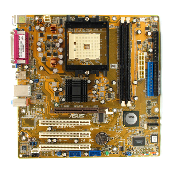
Page 16: Motherboard Overview
USB1 USB2 USBPW12 USBPW34 Bottom: Top: USB3 RJ-45 USB4 K8M800 Top:Line In Center:Line Out Below:Mic In SATA2 VT8237R PCI1 SATA1 K8V-MX PCI2 CR2032 3V 4Mbit Lithium Cell FP_AUDIO Super CMOS Power BIOS PCI3 AD1888 PANEL USBPW56 SB_PWR SPDIF USBPW78 CLRTC... -
Page 17: Placement Direction
Place eight (8) screws into the holes indicated by circles to secure the motherboard to the chassis. Do not overtighten the screws! Doing so may damage the motherboard. Place this side towards the rear of the chassis K8V-MX ASUS K8V-MX Motherboard... -
Page 18: Central Processing Unit (Cpu)
Pin A1 that should match a specific corner of the CPU socket. Gold Arrow K8V-MX K8V-MX CPU Socket 754 Incorrect installation of the CPU into the socket may bend the pins and severely damage the CPU! 1.6.2 Installing the CPU Follow these steps to install a CPU. - Page 19 7. C o n n e c t t h e C P U f a n c a b l e t o t h e C P U _ FA N c o n n e c t o r o n t h e motherboard. ASUS K8V-MX Motherboard...
-
Page 20: System Memory
The following figure illustrates the location of the DDR DIMM sockets. K8V-MX K8V-MX 184-Pin DDR DIMM sockets 1.7.2 Memory configurations You may install 64 MB, 128 MB, 256 MB, 512 MB and 1 GB DDR DIMMs into the DIMM sockets. - Page 21 • 256MB 3208GATA07-04A7 PM4D328D50406EU • • 512MB 3208GATA01-04A4 PM4D328S50403DU • 256MB KINGMAX MPMB62D-38LT3R Mosel V58C2256804SAT6 • • 512MB KINGMAX MPMC22D-38HT3R Hynix HY5DU56822BT-J • • 256MB KINGMAX MPXB62D-38KT3R KINGMAX KDL388P4LA-50 • • (Continued on the next page) ASUS K8V-MX Motherboard 1-11...
- Page 22 DDR400 Qualified Vendors List DIMM support Size Vendor Model Brand Side(s) Component A* B* 256MB Mosel V826632K24SATG-D3 Mosel V58C2256804SAT5 • • 512MB Mosel V826664K24SATG-D3 Mosel V58C2256804SAT5 • 256MB NANYA NT256D64S88B1G-5T NANYA NT5DS32M8BT-5T • • 512MB NANYA NT512D64S8HB1G-5T NANYA NT5DS32M8BT-5T • •...
-
Page 23: Installing A Dimm
DIMM. Support the DIMM lightly with your fingers when pressing the retaining clips. The DIMM might get damaged when it flips out with extra force. 2. Remove the DIMM from the socket. ASUS K8V-MX Motherboard 1-13... -
Page 24: Expansion Slots
1.8 Expansion slots In the future, you may need to install expansion cards. The following sub-sections describe the motherboard slots and the expansion cards that they support. Make sure to unplug the power cord before adding or removing expansion cards. Failure to do so may cause you physical injury and damage motherboard components. -
Page 25: Standard Interrupt Assignments
When using PCI cards on shared slots, ensure that the drivers support “ Share IRQ” or that the cards do not need IRQ assignments; otherwise, conflicts will arise between the two PCI groups, making the system unstable and the card inoperable. ASUS K8V-MX Motherboard 1-15... -
Page 26: Pci Slots
Note the notches on the card golden fingers to ensure that they fit the AGP slot on your motherboard. Install only 1.5V AGP cards on this motherboard! 3.3V AGP cards are not supported in this motherboard. K8V-MX Keyed for 1.5v K8V-MX Accelerated Graphics Port (AGP) 1-16 Chapter 1: Product Introduction... -
Page 27: Jumpers
Except when clearing the RTC RAM, never remove the cap on the CLRTC jumper default position. Removing the cap will cause system boot failure! CLRTC K8V-MX Normal Clear CMOS (Default) K8V-MX Clear RTC RAM ASUS K8V-MX Motherboard 1-17... - Page 28 +5VSB (Default) K8V-MX K8V-MX Keyboard power setting 3. USB device wake-up (3-pin USBPWR12, USBPWR34, USBPWR56, USBPWR78) Set these jumpers to +5V to wake up the computer from S1 sleep mode (CPU stopped, DRAM refreshed, system running in low power mode) using the connected USB devices.
-
Page 29: Connectors
4- or 6-channel audio configuration as shown in the following table. Audio ports function variation Audio ports Headphone /2-Channel 4-Channel 6-Channel Light Blue Line In Rear Speaker Out Rear Speaker Out Lime Line Out Front Speaker Out Front Speaker Out Pink Mic In Mic In Bass/Center ASUS K8V-MX Motherboard 1-19... - Page 30 7. USB 2.0 ports 3 and 4. These two 4-pin Universal Serial Bus (USB) ports are available for connecting USB 2.0 devices. 8. USB 2.0 ports 1 and 2. These two 4-pin Universal Serial Bus (USB) ports are available for connecting USB 2.0 devices 9.
-
Page 31: Internal Connectors
NOTE: Orient the red markings on the floppy ribbon cable to PIN 1. K8V-MX K8V-MX Floppy disk drive connector 2. Internal audio connector (4-pin CD, AUX) These connectors allow you to receive stereo audio input from sound sources such as a CD-ROM, TV tuner, or MPEG card. - Page 32 This connector is for the S/PDIF audio module that allows digital sound input. • Use 75 ohm impedance matched coaxial cables for your S/PDIF connection. • The S/PDIF module is purchased separately. K8V-MX SPDIF_OUT K8V-MX Digital audio connector 1-22 Chapter 1: Product Introduction...
- Page 33 The system can become unstable or will not boot up if the power is inadequate. ATX12V ATXPWR +12V DC +12V DC +3.3VDC +3.3VDC -12.0VDC +3.3VDC PS_ON# +5.0VDC +5.0VDC K8V-MX -5.0VDC PWR_OK +5.0VDC +5VSB +5.0VDC +12.0VDC K8V-MX ATX power connectors ASUS K8V-MX Motherboard 1-23...
- Page 34 K8V-MX SATA connectors 8. Front panel audio connector (10-1 pin FP_AUDIO) ® This interface for the Intel front panel audio cable allows convenient connection and control of audio devices. FP_AUDIO K8V-MX K8V-MX Front panel audio connector 1-24 Chapter 1: Product Introduction...
- Page 35 480 Mbps connection speed. NEVER connect a 1394 cable to the USB connectors. Doing so will damage the motherboard! K8V-MX USB78 USB56 K8V-MX USB 2.0 connectors The USB module is purchased separately. ASUS K8V-MX Motherboard 1-25...
-
Page 36: System Panel Connector
K8V-MX IDE_LED PWRSW Requires an ATX power supply. K8V-MX System panel connector System power LED • This connector is for the system power LED. Connect the chassis power LED cable to this connector. The system power LED lights up when you turn on the system power, and blinks when the system is in sleep mode. -
Page 37: Chapter 2: Bios Information
Chapter 2 This chapter tells how to change system settings through the BIOS Setup menus, and provides detailed descriptions of the BIOS parameters. BIOS Information... -
Page 38: Managing And Updating Your Bios
(Updates the BIOS in DOS mode using a bootable floppy disk.) 2. ASUS EZ Flash (Updates the BIOS using a floppy disk during POST.) 3. ASUS CrashFree BIOS 2 - Updates the BIOS using a bootable floppy disk or the mother board support CD. -
Page 39: Using Afudos To Update The Bios
Write the BIOS filename on a piece of paper. You need to type the exact BIOS file name at the prompt. 2. Copy the AFUDOS.EXE utility from the support CD to the bootable floppy disk that contains the BIOS file. 3. Boot the system from the floppy disk. ASUS K8V-MX Motherboard... - Page 40 4. At the DOS prompt, type the command line: afudos /i[filename.rom] where [filename.rom] means the latest (or original) BIOS file that you copied to the bootable floppy disk. 5. Press <Enter>. The screen displays the status of the update process. The BIOS information on the screen is for reference only.
-
Page 41: Using Asus Ez Flash To Update The Bios
If the correct BIOS file is not found in the floppy disk, the error message “K8V-MX.ROM not found!” is displayed. 4. Insert the floppy disk that contains the BIOS file. If the K8V-MX.ROM file is found in the floppy disk, EZ Flash performs the BIOS update process and automatically reboots the system when done. -
Page 42: Bios Setup Program
2.2 BIOS Setup Program The BIOS software is constantly being updated so the BIOS setup screens and descriptions in this section are for reference purposes only, and may not exactly match what you see on your screen. This motherboard supports a programmable Low Pin Count (LPC) chip that you can update using the provided utility described in section “2.1 Managing and updating your BIOS.”... -
Page 43: Bios Menu Screen
At the bottom right corner of a menu screen are the navigation keys for that particular menu. Use the navigation keys to select items in the menu and change the settings. Some of the navigation keys differ from one screen to another. ASUS K8V-MX Motherboard... -
Page 44: Menu Items
2.2.4 Menu items The highlighted item on the menu bar displays the specific items for that menu. For example, selecting Main shows the Main menu items. The other items (Advanced, Power, Boot, and Exit) on the menu bar have their respective menu items. -
Page 45: Main Menu
[360K, 5.25 in.] [1.2M , 5.25 in.] [720K , 3.5 in.] [1.44M, 3.5 in.] [2.88M, 3.5 in.] 2.3.4 Diskette Write [Disabled] Enabling this item allows you to write to a floppy disk. If set to [Disabled], the floppy disk is write-protected.Configuration options: [Disabled] [Enabled] ASUS K8V-MX Motherboard... -
Page 46: Primary/Secondary Ide Master/Slave
2.3.5 Primary/Secondary IDE Master/Slave While entering Setup, BIOS automatically detects the presence of IDE devices. There is a separate sub-menu for each IDE device. Select a device item then press <Enter> to display the IDE device information. Primary IDE Master Select the type of device connected Device... -
Page 47: System Information
BIOS. AMI BIOS Version : 08.00.09 Revision : 01.07.1711 Build Date : 06/14/05 : A0310001 System Memory Size : 256MB AMI BIOS Displays the auto-detected BIOS information. System Memory Displays the auto-detected system memory. ASUS K8V-MX Motherboard 2-11... -
Page 48: Advanced Menu
2.4 Advanced menu The Advanced menu items allow you to change the settings for the CPU and other system devices. Take caution when changing the settings of the Advanced menu items. Incorrect field values can cause the system to malfunction. Configure CPU. - Page 49 Configuration options: [200MHz] [400MHz] [600MHz] [800MHz] HT DATA Width (Upstream) [16BIT] Allows selection of Hyper Transport upstream data width. Configuration options: [16BIT] [8BIT] HT DATA Width (Downstream) [16BIT] Allows selection of Hyper Transport downstream data width. Configuration options: [16BIT] [8BIT] ASUS K8V-MX Motherboard 2-13...
- Page 50 Memory Configuration Memory Configuration Memory Configuration Memory Configuration Memory Configuration MEMCLK can be set by the code using Memclock Mode [Auto] AUTO, or if you use MCT Timing Mode [Auto] LIMIT, you can set User Config Mode [Auto] one of the standard Burst Length [4 Beats] values.
-
Page 51: Chipset
Enables or disables support for 18-bit LCD panel to 24-bit color depth under different resolutions. Configuration options: [Disabled] [Enabled] Primary Graphics Adapter [AGP] Allows you to select the mode of Primary Graphics Adapter. Configuration options: [AGP] [PCI] ASUS K8V-MX Motherboard 2-15... - Page 52 Search for MDA Resources [No] Sets whether to allow search for MDA resources. Configuration options: [No] [Yes] VLink 8X supported [Enabled] Enables or disables support for VLink 8X. Configuration options: [Disabled] [Enabled] AGP Mode [AGP 8X] This motherboard supports the AGP 8X interface that transfers video data at 2.12GB/s.
- Page 53 Change Option General Help Save and Exit Exit v02.54 (C)Copyright 1985-2003, American Megatrends, Inc. The Module Version and USB Devices Enabled items show the auto-detected values. If no USB device is detected, the item shows None. ASUS K8V-MX Motherboard 2-17...
- Page 54 USB 1.1 Ports Configuration [USB 8 Ports] Allows you to set the number of USB ports to activate. Configuration options: [Disabled] [USB 2 Ports] [USB 4 Ports] [USB 6 Ports] [USB 8 Ports] USB 2.0 Controller [Enabled] Allows you to enable or disable the USB 2.0 controller. Configuration options: [Enabled] [Disabled] Legacy USB Support [Auto] Allows you to enable or disable support for legacy USB devices.
-
Page 55: Onboard Devices Configuration
Parallel Port IRQ [IRQ7] ←→ Select Item ↑↓ Change Option General Help Save and Exit Exit v02.54 (C)Copyright 1985-2003, American Megatrends, Inc. Onboard Floppy Controller [Enabled] Enables or disables the Onboard Floppy Controller. Configuration options: [Enabled] [Disabled] ASUS K8V-MX Motherboard 2-19... - Page 56 OnBoard ACʼ97 Audio [Enabled] Selecting [Enabled] allows the BIOS to detect whether you are using any audio device. If an audio device is detected, the onboard audio controller is enabled. If no audio device is detected, the controller is disabled. Configuration options: [Enabled] [Disabled] OnChip SATA [Enabled] Enables or disables the OnChip Serial ATA.
-
Page 57: Pci Pnp
Configuration options: [Disabled] [Enabled] IRQ xx [Available] When set to [Available], the specific IRQ is free for use of PCI/PnP devices. When set to [Reserved], the IRQ is reserved for legacy ISA devices. Configuration options: [PCI Device] [Reserved] ASUS K8V-MX Motherboard 2-21... -
Page 58: System Frequency/Voltage Configuration
2.4.5 System Frequency/Voltage Configuration The System Frequency/Voltage Configuration menu items allow you to config the advanced settings for system frequency and voltage. Config System Frequency/Voltage Enable/Disable clock generator spread AI Overclocking [Auto] spectrum Cool N’Quiet [Enabled] Select Screen ←→ Select Item ↑↓... -
Page 59: Power Menu
[No] [Yes] 2.5.4 ACPI APIC Support [Enabled] Enables or disables the ACPI support in the ASIC. When set to Enabled, the ACPI APIC table pointer is included in the RSDT pointer list. Configuration options: [Disabled] [Enabled] ASUS K8V-MX Motherboard 2-23... -
Page 60: Apm Configuration
2.5.5 APM Configuration Power Management/APM [Enabled] Enable or disable the Advanced Power Power Button Mode [On/Off] Management (APM) Suspend Power Saving Type [C3] feature. Restore on AC Power Loss [Last State] Standby Iime Out [Disabled] Resume On Ring [Disabled] Power On Lan [Disabled] Power On PME [Disabled]... - Page 61 This feature requires an ATX power supply that provides at least 1A on the +5VSB lead. Configuration options: [Disabled] [Enabled] Power On OnBoard LAN [Enabled] When set to [Enabled], this option allows you to use the onboard LAN to turn on the system. Configuration options: [Enabled] [Disabled] ASUS K8V-MX Motherboard 2-25...
-
Page 62: Hardware Monitor
2.5.6 Hardware Monitor CPU Temperature CPU Temperature [37.5°C/99.5°F] MB Temperature [34°C/93°F] CPU Fan Speed [3214RPM] VCORE Voltage [1.424V] 3.3V Voltage [3.328V] 5V Voltage [5.232V] 12V Voltage [11.668V] Select Screen ←→ Select Item ↑↓ Change Option General Help Save and Exit Exit v02.54 (C)Copyright 1985-2003, American Megatrends, Inc. -
Page 63: Boot Menu
) may appear when you Security set the CD-ROM drive as the first boot device. Select Screen ←→ Select Item ↑↓ Enter Go to Sub Screen General Help Save and Exit Exit v02.54 (C)Copyright 1985-2003, American Megatrends, Inc. ASUS K8V-MX Motherboard 2-27... -
Page 64: Boot Device Priority
1st Boot Device [1st FLOPPY DRIVE] 2nd Boot Device [PM-ST340014A] A device enclosed in 3rd Boot Device [SM-ASUS DVD-E616P2] parenthesis has been disabled in the corresponding type menu. 1st ~ xxth Boot Device [1st FLOPPY DRIVE] These items specify the boot device priority sequence from the available devices. -
Page 65: Boot Settings Configuration
Allows you to enable or disable the full screen logo display feature. Configuration options: [Enabled] [Disabled] Set this item to [Enabled] to use the ASUS MyLogo™ feature. AddOn ROM Display Mode [Force BIOS] Sets the display mode for option ROM. -
Page 66: Security
Hit ʻDELʼ Message Display [Enabled] When set to [Enabled], the system displays the message “Press DEL to run Setup” during POST. Configuration options: [Enabled] [Disabled] Interrupt 19 Capture [Disabled] When set to [Enabled], this function allows the option ROMs to trap Interrupt 19. Configuration options: [Disabled] [Enabled] 2.6.3 Security The Security menu items allow you to change the system security settings. -
Page 67: Exit Menu
Setup menus. When you select this option, or if you press <F5>, a confirmation window appears. Select [Yes] to load the default values. Select Exit & Save Changes or make other changes before saving the values to the non-volatile RAM. ASUS K8V-MX Motherboard 2-31... - Page 68 2-32 Chapter 2: BIOS Information...
-
Page 69: Software Support
Chapter 3 This chapter describes the contents of the support CD that comes with the motherboard package. Software Support... -
Page 70: Chapter 3: Software Support
The contents of the support CD are subject to change at any time without notice. Visit the ASUS website(www.asus.com) for updates. 3.2.1 Running the support CD Place the support CD to the optical drive. The CD automatically displays the Drivers menu if Autorun is enabled in your computer. -
Page 71: Drivers Menu
These changes can happen as often as 30 times per second. The screen display and drivers option may not be the same for different operating system versions. 3.2.3 Utilities menu The Utilities menu shows the applications and other software that the motherboard supports. ASUS K8V-MX Motherboard... -
Page 72: Contacts Menu
Cool ʻnʼ Quiet Software Install ASUS CoolQuiet Software. 3.2.4 Contacts menu Click the Contact tab to display the ASUS contact information. You can also find this information on the inside front cover of this user guide. Chapter 3: Software Support...