Table of Contents
Advertisement
Quick Links
Advertisement
Table of Contents

Related Manuals for Asus K8N-DL


Summary of Contents for Asus K8N-DL
- Page 1 K8N-DL...
- Page 2 Product warranty or service will not be extended if: (1) the product is repaired, modified or altered, unless such repair, modification of alteration is authorized in writing by ASUS; or (2) the serial number of the product is defaced or missing.
-
Page 3: Table Of Contents
Contents Notices ... vi Safety information ... vii About this guide ... viii Typography ... ix K8N-DL specifications summary ... x Chapter 1: Product introduction Chapter 1: Product introduction Chapter 1: Product introduction Chapter 1: Product introduction Chapter 1: Product introduction Welcome! ... - Page 4 4.1.2 Updating the BIOS ... 4-2 4.1.3 Saving the current BIOS file ... 4-4 4.1.4 ASUS CrashFree BIOS 2 utility ... 4-5 4.1.5 ASUS EZ Flash utility ... 4-7 4.1.6 ASUS Update utility ... 4-8 BIOS setup program ... 4-11 4.2.1...
- Page 5 Removable Device Priority ... 4-40 4.6.4 Boot Settings Configuration ... 4-41 4.6.5 Security ... 4-43 Exit menu ... 4-45 Appendix: Reference information Appendix: Reference information Appendix: Reference information Appendix: Reference information Appendix: Reference information K8N-DL block diagram ... A-1 v v v v v...
-
Page 6: Notices
Notices Federal Communications Commission Statement Federal Communications Commission Statement Federal Communications Commission Statement Federal Communications Commission Statement Federal Communications Commission Statement This device complies with Part 15 of the FCC Rules. Operation is subject to the following two conditions: • This device may not cause harmful interference, and •... -
Page 7: Safety Information
Safety information Electrical safety Electrical safety Electrical safety Electrical safety Electrical safety • To prevent electrical shock hazard, disconnect the power cable from the electrical outlet before relocating the system. • When adding or removing devices to or from the system, ensure that the power cables for the devices are unplugged before the signal cables are connected. -
Page 8: About This Guide
A S U S w e b s i t e s A S U S w e b s i t e s The ASUS website provides updated information on ASUS hardware and software products. Refer to the ASUS contact information. -
Page 9: Typography
Conventions used in this guide Conventions used in this guide Conventions used in this guide Conventions used in this guide Conventions used in this guide To make sure that you perform certain tasks properly, take note of the following symbols used throughout this manual. D A N G E R / W A R N I N G : D A N G E R / W A R N I N G : D A N G E R / W A R N I N G :... -
Page 10: K8N-Dl Specifications Summary
K8N-DL specifications summary C P U C P U C P U C P U C P U C h i p s e t C h i p s e t C h i p s e t C h i p s e t... - Page 11 K8N-DL specifications summary 1 x Floppy disk drive connector I n t e r n a l I n t e r n a l I n t e r n a l I n t e r n a l...
- Page 12 x i i x i i x i i x i i x i i...
- Page 13 This chapter describes the motherboard features and the new technologies it supports. Product introduction...
- Page 14 Chapter summary Welcome! ... 1-1 Package contents ... 1-1 Special features ... 1-2 A S U S K 8 N - D L A S U S K 8 N - D L A S U S K 8 N - D L A S U S K 8 N - D L A S U S K 8 N - D L...
-
Page 15: Welcome
T h a n k y o u f o r b u y i n g a n A S U S The motherboard delivers a host of new features and latest technologies, making it another standout in the long line of ASUS quality motherboards! Before you start installing the motherboard, and hardware devices on it, check the items in your package with the list below. -
Page 16: Special Features
Special features 1.3.1 1.3.1 1.3.1 Product highlights Product highlights Product highlights 1.3.1 1.3.1 Product highlights Product highlights Latest processor technology Latest processor technology Latest processor technology Latest processor technology Latest processor technology The motherboard comes with dual 940-pin sockets for the AMD Opteron™ 64 processors. - Page 17 Dual RAID solution Dual RAID solution Dual RAID solution Dual RAID solution Dual RAID solution Onboard RAID controllers provide the motherboard with dual-RAID functionality that allows you to select the best RAID solution using IDE or Serial ATA devices. The NVIDIA ®...
-
Page 18: Innovative Asus Features
ASUS Smart Fan technology ASUS Smart Fan technology ASUS Smart Fan technology The ASUS Smart Fan technology smartly adjusts the fan speeds according to the system loading to ensure quiet, cool, and efficient operation. See page 4-38 for details. ASUS POST Reporter™... - Page 19 This chapter lists the hardware setup procedures that you have to perform when installing system components. It includes description of the jumpers and connectors on the motherboard. Hardware information...
- Page 20 Chapter summary Before you proceed ... 2-1 Motherboard overview ... 2-3 Central Processing Unit (CPU) ... 2-7 System memory ... 2-11 Expansion slots ... 2-14 Jumpers ... 2-17 Connectors ... 2-20 A S U S K 8 N - D L A S U S K 8 N - D L A S U S K 8 N - D L A S U S K 8 N - D L...
-
Page 21: Before You Proceed
® K8N-DL K8N-DL Standby power LED A S U S K 8 N - D L A S U S K 8 N - D L A S U S K 8 N - D L... - Page 22 The CPU warning LED lights up to indicate that CPU1 has not been installed properly. If this LED stays off, this means that CPU has been installed properly. ® K8N-DL K8N-DL CPU warning LED 2 - 2 2 - 2 2 - 2 2 - 2...
-
Page 23: Motherboard Overview
A S U S K 8 N - D L A S U S K 8 N - D L A S U S K 8 N - D L ® K8N-DL 2 - 3 2 - 3 2 - 3... -
Page 24: Motherboard Layout
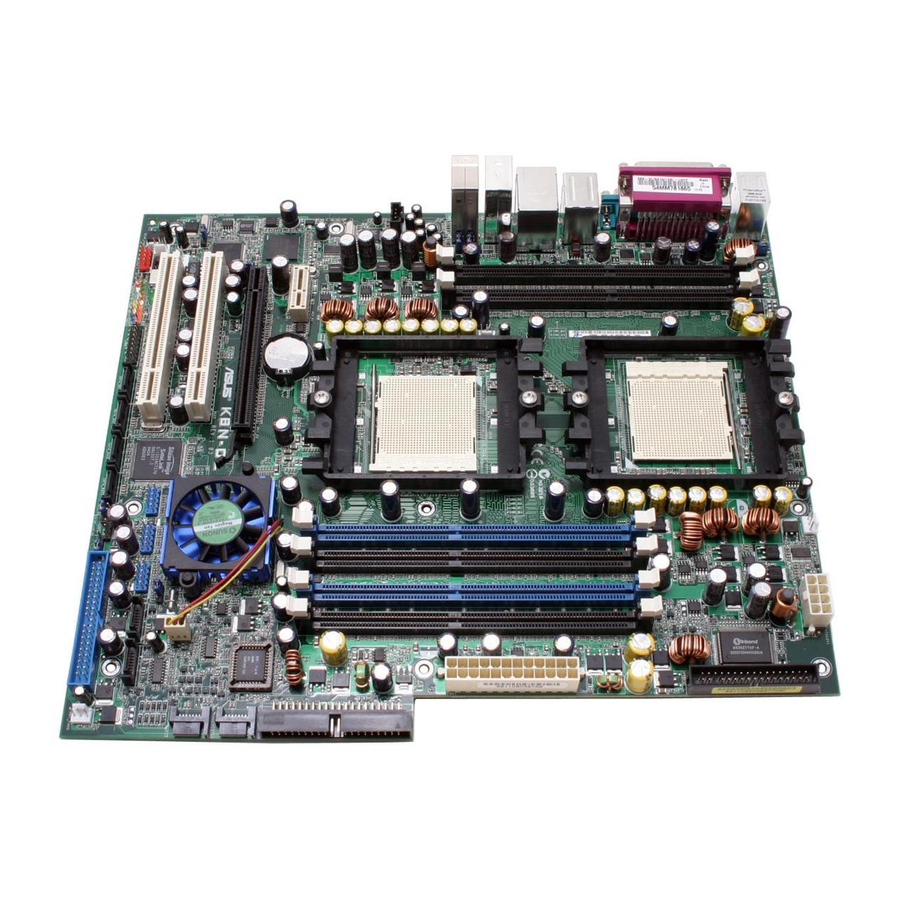
PANEL1 REAR_FAN1 IEEE1394_1 2 - 4 2 - 4 2 - 4 2 - 4 2 - 4 26.7cm (10.5in) CPU_FAN2 CPU2 CPU1 PCI_E2 ® K8N-DL Professional PCI2 USB56 Silicon Image SATALink PCI1 Sil3114CT176 CPU_WARN1 BPSMB1 GAME1 SATA_RAID1 SATA_RAID2 SATA_RAID3... -
Page 25: Layout Contents
2.2.4 2.2.4 Layout Contents Layout Contents 2.2.4 2.2.4 2.2.4 Layout Contents Layout Contents Layout Contents S l o t s / S o c k e t s S l o t s / S o c k e t s S l o t s / S o c k e t s S l o t s / S o c k e t s S l o t s / S o c k e t s... - Page 26 I n t e r n a l c o n n e c t o r s I n t e r n a l c o n n e c t o r s I n t e r n a l c o n n e c t o r s I n t e r n a l c o n n e c t o r s I n t e r n a l c o n n e c t o r s Floppy disk drive connector (34-1 pin FLOPPY1)
-
Page 27: Installing The Cpu
Locate the CPU socket on the motherboard. CPU2 CPU1 ® K8N-DL K8N-DL CPU Socket 940 • Before installing the CPU, make sure that the socket box is facing towards you and the load lever is on your left. • If installing only one CPU, use the CPU socket marked CPU1. - Page 28 Unlock the socket by pressing the lever sideways, then lift it up to a 90°-100° angle. Make sure that the socket lever is lifted up to 90°-100° angle, otherwise the CPU does not fit in completely. Position the CPU above the socket such that the notched corner matches the socket corner with a triangle mark.
-
Page 29: Installing The Heatsink And Fan
2.3.3 2.3.3 2.3.3 2.3.3 2.3.3 Installing the heatsink and fan Installing the heatsink and fan Installing the heatsink and fan Installing the heatsink and fan Installing the heatsink and fan The AMD Opteron™ 64 processors require a specially designed heatsink and fan assembly to ensure optimum thermal condition and performance. - Page 30 Attach one end of the retention bracket to the retention module base. Align the other end of the retention bracket (near the retention bracket lock) to the retention module base. A clicking sound denotes that the retention bracket is in place. Make sure that the fan and heatsink assembly perfectly fits the retention mechanism...
-
Page 31: System Memory
Inline Memory Modules (DIMM) sockets. The following figure illustrates the location of the sockets: ® K8N-DL K8N-DL 184-pin DDR DIMM sockets F o r C P U 1 F o r C P U 1 F o r C P U 1... -
Page 32: Memory Configurations
2.4.2 2.4.2 2.4.2 Memory Configurations Memory Configurations Memory Configurations 2.4.2 2.4.2 Memory Configurations Memory Configurations You may install 256 MB, 512 MB, 1 GB, 2 GB, or 4 GB registered ECC DDR DIMMs into the DIMM sockets using the memory configurations in this section. -
Page 33: Installing A Dimm
2.4.3 2.4.3 2.4.3 Installing a DIMM Installing a DIMM Installing a DIMM 2.4.3 2.4.3 Installing a DIMM Installing a DIMM Make sure to unplug the power supply before adding or removing DIMMs or other system components. Failure to do so may cause severe damage to both the motherboard and the components. -
Page 34: Expansion Slots
Expansion slots In the future, you may need to install expansion cards. The following sub-sections describe the slots and the expansion cards that they support. Make sure to unplug the power cord before adding or removing expansion cards. Failure to do so may cause you physical injury and damage motherboard components. -
Page 35: Interrupt Assignments
2.5.3 2.5.3 Interrupt assignments Interrupt assignments 2.5.3 2.5.3 2.5.3 Interrupt assignments Interrupt assignments Interrupt assignments Standard interrupt assignments Standard interrupt assignments Standard interrupt assignments Standard interrupt assignments Standard interrupt assignments I R Q I R Q P r i o r i t y P r i o r i t y I R Q I R Q... -
Page 36: Pci Slots
2.5.4 2.5.4 PCI slots PCI slots 2.5.4 2.5.4 2.5.4 PCI slots PCI slots PCI slots The PCI slots support cards such as a LAN card, SCSI card, USB card, and other cards that comply with PCI specifications. The figure shows a LAN card installed on a PCI slot. -
Page 37: Jumpers
Removing the cap will cause system boot failure! ® K8N-DL K8N-DL Clear RTC RAM You do not need to clear the RTC when the system hangs due to overclocking. For system failure due to overclocking, use the C.P.R. (CPU Parameter Recall) feature. - Page 38 ® K8N-DL K8N-DL Keyboard power setting 3 . 3 . 1 3 9 4 c o n t r o l l e r s e t t i n g ( 3 - p i n 1 3 9 4 _ E N 1 )
- Page 39 ® K8N-DL K8N-DL CPU LAN1_EN setting 5 . 5 . R A I D c o n t r o l l e r s e t t i n g ( 3 - p i n R A I D _ E N 1 )
-
Page 40: Connectors
Connectors 2.7.1 2.7.1 2.7.1 Rear panel connectors Rear panel connectors Rear panel connectors 2.7.1 2.7.1 Rear panel connectors Rear panel connectors 1 . 1 . P S / 2 m o u s e p o r t ( g r e e n ) . P S / 2 m o u s e p o r t ( g r e e n ) . - Page 41 9 . 9 . M i c r o p h o n e p o r t ( p i n k ) . M i c r o p h o n e p o r t ( p i n k ) . M i c r o p h o n e p o r t ( p i n k ) .
-
Page 42: Internal Connectors
® K8N-DL K8N-DL Floppy disk drive connector 2 . 2 . I D E c o n n e c t o r s ( 4 0 - 1 p i n P R I _ I D E 1 , S E C _ I D E 1 ) - Page 43 ® K8N-DL K8N-DL SATA connectors I m p o r t a n t n o t e s o n S e r i a l A T A I m p o r t a n t n o t e s o n S e r i a l A T A...
- Page 44 Silicon Image Sil3114 SATA RAID controller. ® K8N-DL K8N-DL SATA RAID connectors • Before creating a RAID configuration, make sure that you have connected the Serial ATA cables to these connectors and have installed the Serial ATA hard disks drives; otherwise, you cannot enter the Silicon Image RAID utility and Serial ATA BIOS setup during POST.
- Page 45 These are not jumpers! DO NOT place jumper caps on the fan connectors! • The ASUS Smart Q-Fan function is supported using the CPU fans (CPU_FAN1, CPU_FAN2) connectors. • The chipset fan is synchronized with the CPU fans.
- Page 46 USB connectors comply with USB 2.0 specification that supports up to 480 Mbps connection speed. ® K8N-DL K8N-DL USB 2.0 connectors Never connect a 1 3 9 4 c a b l e damage the motherboard! 8 . 8 .
- Page 47 See the table below for details. ® K8N-DL K8N-DL ATX Power connectors A S U S K 8 N - D L A S U S K 8 N - D L A S U S K 8 N - D L...
- Page 48 These connectors allow you to receive stereo audio input from sound sources such as a CD-ROM. ® K8N-DL K8N-DL Internal audio connector The function of this connector is disabled in 8-channel mode. 2 - 2 8 2 - 2 8...
- Page 49 I/O module cable to this connector. ® K8N-DL K8N-DL Front panel audio connector A S U S K 8 N - D L A S U S K 8 N - D L A S U S K 8 N - D L...
-
Page 50: System Panel Connector
This connector supports several chassis-mounted functions. ® K8N-DL K8N-DL System panel connector The system panel connector is color-coded for easy connection. Refer to the connector description below for details. S y s t e m p o w e r L E D ( G r e e n 3 - p i n P L E D ) S y s t e m p o w e r L E D ( G r e e n 3 - p i n P L E D ) •... - Page 51 This chapter describes the power up sequence, the vocal POST messages, and ways of shutting down the system. Powering up...
- Page 52 Chapter summary Starting up for the first time ... 3-1 Powering off the computer ... 3-2 ASUS POST Reporter™ ... 3-3 A S U S K 8 N - D L A S U S K 8 N - D L...
-
Page 53: Starting Up For The First Time
Starting up for the first time After making all the connections, replace the system case cover. Be sure that all switches are off. Connect the power cord to the power connector at the back of the system chassis. Connect the power cord to a power outlet that is equipped with a surge protector. -
Page 54: Powering Off The Computer
Powering off the computer 3.2.1 3.2.1 3.2.1 Using the OS shut down function Using the OS shut down function Using the OS shut down function 3.2.1 3.2.1 Using the OS shut down function Using the OS shut down function If you are using Windows Click the S t a r t S t a r t S t a r t... -
Page 55: Asus Post Reporter
ASUS POST Reporter™ This motherboard includes the Winbond speech controller to support a special feature called the ASUS POST Reporter™. This feature lets you hear vocal messages during POST that alerts you of system events and boot status. In case of a boot failure, you will hear the specific cause of the problem. - Page 56 Computer now booting from operating system You can enable or disable the ASUS POST Reporter™ in the S p e e c h I C R e p o r t e r R e p o r t e r R e p o r t e r item in the BIOS setup.
-
Page 57: Winbond Voice Editor
The Winbond Voice Editor software allows you to customize the vocal POST messages. You can install this application from the support CD. To avoid conflicts, do not run the Winbond Voice Editor while running the ASUS PC Probe application. Launching the Voice Editor Launching the Voice Editor... - Page 58 Y e s to confirm. Y e s Y e s Y e s The next time you boot your computer, the ASUS Post Reporter announces the messages in the selected language. 3 - 6 3 - 6 3 - 6...
- Page 59 Customizing your POST messages Customizing your POST messages Customizing your POST messages Customizing your POST messages Customizing your POST messages The Voice Editor application allows you to record your own POST messages if your language is not supported or if you wish to to replace the pre-installed wave files.
- Page 60 Select a POST event on the Voice Editor main window, then click the E d i t E d i t E d i t button. The E d i t E d i t E v e n t S o u n d E d i t o r E v e n t S o u n d E d i t o r E v e n t S o u n d E d i t o r window E v e n t S o u n d E d i t o r...
-
Page 61: Chapter 4: Bios Setup
This chapter tells how to change the system settings through the BIOS Setup menus. Detailed descriptions of the BIOS parameters are also provided. BIOS setup... - Page 62 Chapter summary Managing and updating your BIOS ... 4-1 BIOS setup program ... 4-11 Main menu ... 4-15 Advanced menu ... 4-20 Power menu ... 4-33 Boot menu ... 4-39 Exit menu ... 4-45 A S U S K 8 N - D L A S U S K 8 N - D L A S U S K 8 N - D L A S U S K 8 N - D L...
-
Page 63: Managing And Updating Your Bios
Save a copy of the original motherboard BIOS file to a bootable floppy disk in case you need to restore the BIOS in the future. Copy the original motherboard BIOS using the ASUS Update or AwardBIOS Flash utilities. 4.1.1 4.1.1 4.1.1... -
Page 64: Updating The Bios
AwardBIOS Flash Utility. Follow these instructions to update the BIOS using this utility. 1. Download the latest BIOS file from the ASUS web site. Rename the file K 8 N - D L . B I N K 8 N - D L . B I N to K 8 N - D L . - Page 65 A S U S K 8 N - D L A S U S K 8 N - D L A S U S K 8 N - D L AwardBIOS Flash Utility for ASUS V1.01 (C) Phoenix Technologies Ltd. All Rights Reserved For NF-KC804-K8N-DL-00 DATE: 02/01/2005 Flash Type - SST 49LF004A/B /3.3V...
-
Page 66: Saving The Current Bios File
4 - 4 4 - 4 4 - 4 4 - 4 4 - 4 AwardBIOS Flash Utility for ASUS V1.01 (C) Phoenix Technologies Ltd. All Rights Reserved For NF-KC804-K8N-DL-00 DATE: 02/01/2005 Flash Type - SST 49LF004A/B /3.3V File Name to Program: 1001.bin... -
Page 67: Asus Crashfree Bios 2 Utility
ASUS CrashFree BIOS 2 utility ASUS CrashFree BIOS 2 utility The ASUS CrashFree BIOS 2 is an auto recovery tool that allows you to restore the BIOS file when it fails or gets corrupted during the updating process. You can update a corrupted BIOS file using the motherboard support CD or the floppy disk that contains the updated BIOS file. - Page 68 Restart the system after the utility completes the updating process. The recovered BIOS may not be the latest BIOS version for this motherboard. Visit the ASUS website (www.asus.com) to download the latest BIOS file. 4 - 6...
-
Page 69: Asus Ez Flash Utility
ASUS EZ Flash utility ASUS EZ Flash utility The ASUS EZ Flash feature allows you to update the BIOS without having to go through the long process of booting from a floppy disk and using a DOS-based utility. The EZ Flash utility is built-in the BIOS chip so it is accessible by pressing <Alt>... -
Page 70: Asus Update Utility
4.1.6 ASUS Update utility ASUS Update utility ASUS Update utility The ASUS Update is a utility that allows you to manage, save, and update the motherboard BIOS in Windows allows you to: • Save the current BIOS file • Download the latest BIOS file from the Internet •... - Page 71 Updating the BIOS through the Internet Updating the BIOS through the Internet To update the BIOS through the Internet: Launch the ASUS Update utility from the Windows S t a r t S t a r t P r o g r a m s...
- Page 72 A S U S U p d a t e A S U S U p d a t e A S U S U p d a t e. The ASUS Update main window appears. A S U S U p d a t e...
-
Page 73: Bios Setup Program
• Visit the ASUS website (www.asus.com) to download the latest BIOS file for this motherboard. A S U S K 8 N - D L A S U S K 8 N - D L... -
Page 74: Bios Menu Screen
4.2.1 4.2.1 BIOS menu screen BIOS menu screen 4.2.1 4.2.1 4.2.1 BIOS menu screen BIOS menu screen BIOS menu screen M e n u i t e m s M e n u i t e m s M e n u b a r M e n u b a r M e n u i t e m s M e n u i t e m s... -
Page 75: Legend Bar
4.2.3 4.2.3 Legend bar Legend bar 4.2.3 4.2.3 4.2.3 Legend bar Legend bar Legend bar At the bottom of the Setup screen is a legend bar. The keys in the legend bar allow you to navigate through the various setup menus. The following table lists the keys found in the legend bar with their corresponding functions. -
Page 76: Pop-Up Window
4.2.7 4.2.7 Pop-up window Pop-up window 4.2.7 4.2.7 4.2.7 Pop-up window Pop-up window Pop-up window Select a menu item then press <Enter> to display a pop-up window with the configuration options for that item. Main Advanced Power System Time System Date Legacy Diskette A Floppy 3 Mode Support Primary IDE Master... -
Page 77: Main Menu
Main menu When you enter the BIOS Setup program, the Main menu screen appears, giving you an overview of the basic system information. Refer to section “4.2.1 BIOS menu screen” for information on the menu screen items and how to navigate through them. Phoenix-Award BIOS CMOS Setup Utility Main Advanced... -
Page 78: Primary Ide Master
While entering Setup, the BIOS automatically detects the presence of IDE devices. There is a separate sub-menu for each IDE device. Select a device item then press <Enter> to display the IDE device information. 4.3.6 4.3.6 Primary IDE Master Primary IDE Master 4.3.6 4.3.6 4.3.6... - Page 79 Access Mode [Auto] Access Mode [Auto] Access Mode [Auto] Access Mode [Auto] Access Mode [Auto] Allows selection of the sector addressing mode. The default [Auto] allows automatic detection of an IDE hard disk drive. Select [CHS] for this item if you set the Primary IDE Master to [Manual] to manually enter the drive information.
-
Page 80: Primary Ide Slave
H e a d H e a d H e a d H e a d H e a d Shows the number of the hard disk read/write heads. Precomp Precomp Precomp Precomp Precomp Displays the precompressed volumes on the hard disk, if any. Landing Zone Landing Zone Landing Zone... -
Page 81: Third Ide Master
4.3.10 4.3.10 Third IDE Master Third IDE Master 4.3.10 4.3.10 4.3.10 Third IDE Master Third IDE Master Third IDE Master When configuring a drive as Primary IDE Slave, refer to section “4.3.6 Primary IDE Master” for the menu item descriptions which are not discussed in this section. -
Page 82: Advanced Menu
Advanced menu The Advanced menu items allow you to change the settings for the CPU and other system devices. Take caution when changing the settings of the Advanced menu items. Incorrect field values can cause the system to malfunction. Main Advanced Power CPU Configuration... -
Page 83: Memory Configuration
CPU Frequency [200.0] CPU Frequency [200.0] CPU Frequency [200.0] CPU Frequency [200.0] CPU Frequency [200.0] Allows you to select the CPU frequency. Configuration options: [200.0] [201.0] [202.0] ... [400.0] AMD K8 Cool ‘n’ Quiet Control [Enabled] AMD K8 Cool ‘n’ Quiet Control [Enabled] AMD K8 Cool ‘n’... - Page 84 CAS# Latency (Tcl) [2.5] CAS# Latency (Tcl) [2.5] CAS# Latency (Tcl) [2.5] CAS# Latency (Tcl) [2.5] CAS# Latency (Tcl) [2.5] Sets the latency (in clocks) between the DRAM read command and the time the data actually becomes available. Configuration options: [2] [2.5] [3] Min RAS# Active Time (Tras) [ 8T] Min RAS# Active Time (Tras) [ 8T] Min RAS# Active Time (Tras) [ 8T]...
-
Page 85: Chipset
Chip-Kill Mode Enable [Disabled] Chip-Kill Mode Enable [Disabled] Chip-Kill Mode Enable [Disabled] Chip-Kill Mode Enable [Disabled] Chip-Kill Mode Enable [Disabled] When set to [Enabled], allows ECC checking to be based on a 128/16 data/ECC rather than on a 64/8 data/ECC. You may only enable this feature in 128-bit DRAM data width mode. - Page 86 OnChip IDE Channel0 [Enabled] OnChip IDE Channel0 [Enabled] OnChip IDE Channel0 [Enabled] OnChip IDE Channel0 [Enabled] OnChip IDE Channel0 [Enabled] Enables or disables the on-chip IDE channel 0. Configuration options: [Disabled] [Enabled] OnChip IDE Channel1 [Enabled] OnChip IDE Channel1 [Enabled] OnChip IDE Channel1 [Enabled] OnChip IDE Channel1 [Enabled] OnChip IDE Channel1 [Enabled]...
- Page 87 Init Display First [PCI Slot] Init Display First [PCI Slot] Init Display First [PCI Slot] Init Display First [PCI Slot] Init Display First [PCI Slot] Allows you to select the graphics controller to use as primary boot device. Configuration options: [PCI Slot] [PCIEx] IDE DMA Transfer Access [Enabled] IDE DMA Transfer Access [Enabled] IDE DMA Transfer Access [Enabled]...
-
Page 88: Onboard Device
4.4.4 4.4.4 Onboard Device Onboard Device 4.4.4 4.4.4 4.4.4 Onboard Device Onboard Device Onboard Device This menu shows the onboard device configuration settings. Select an item then press <Enter> to display a pop-up menu with the configuration options, or a sub-menu with additional items. Speech IC Reporter Report IDE Error Report System Booting... - Page 89 Onboard Broadcom 5751 LAN [Enabled] Onboard Broadcom 5751 LAN [Enabled] Onboard Broadcom 5751 LAN [Enabled] Onboard Broadcom 5751 LAN [Enabled] Onboard Broadcom 5751 LAN [Enabled] Enables or disables the onboard LAN controller. Configuration options: [Disabled] [Enabled] Onboard AC97 Audio [Enabled] Onboard AC97 Audio [Enabled] Onboard AC97 Audio [Enabled] Onboard AC97 Audio [Enabled]...
- Page 90 Super I/O Device Super I/O Device Super I/O Device Super I/O Device Super I/O Device This sub-menu contains RAID-related function items. Select the items that you wish to enable to create a RAID set. NVRAID Configuration Serial Port1 Address Onboard Parallel Port Parallel Port Mode EPP Mode Select ECP Mode Use DMA...
- Page 91 ECP Mode Use DMA [3] Allows you to configure the parallel port DMA channel for the selected ECP mode. This item becomes configurable only if the P a r a l l e l P o r t M o d e M o d e is set to [ECP] or [ECP+EPP].
-
Page 92: Pcipnp
4.4.5 4.4.5 PCIPnP PCIPnP 4.4.5 4.4.5 4.4.5 PCIPnP PCIPnP PCIPnP This menu shows the PCIPnP configuration settings. Select an item then press <Enter> to display a pop-up menu with the configuration options. Memory Configuration Resources Controlled By IRQ Resources PCI/VGA Pallete Snoop ** PCI Express relative items ** Maximum Payload Size Resources Controlled By [Auto]... - Page 93 IRQ Resources IRQ Resources IRQ Resources IRQ Resources IRQ Resources Set the item R e s o u r c e s C o n t r o l l e d B y R e s o u r c e s C o n t r o l l e d B y R e s o u r c e s C o n t r o l l e d B y to [Manual] to enable the R e s o u r c e s C o n t r o l l e d B y R e s o u r c e s C o n t r o l l e d B y...
-
Page 94: Usb Configuration
4.4.6 4.4.6 USB Configuration USB Configuration 4.4.6 4.4.6 4.4.6 USB Configuration USB Configuration USB Configuration This menu shows the USB configuration settings. Select an item then press <Enter> to display a pop-up menu with the configuration options. USB Controller USB2.0 Controller USB Legacy Mode Support USB Controller [Enabled] USB Controller [Enabled]... -
Page 95: Power Menu
Power menu The Power menu items allow you to change the settings for the ACPI and Advanced Power Management (APM) features. Select an item then press <Enter> to display the configuration options. ACPI APIC Support ACPI Suspend Type APM Configuration Hardware Monitor ACPI APIC Support [Enabled] ACPI APIC Support [Enabled]... -
Page 96: Apm Configuration
4.5.1 4.5.1 APM Configuration APM Configuration 4.5.1 4.5.1 4.5.1 APM Configuration APM Configuration APM Configuration This menu shows the Advanced Powed Management (APM) configuration settings. Select an item then press <Enter> to display a pop-up menu with the configuration options. Power Management HDD Power Down Video Off Method... - Page 97 Restore on AC Power Loss [Power Off] Restore on AC Power Loss [Power Off] Restore on AC Power Loss [Power Off] Restore on AC Power Loss [Power Off] Restore on AC Power Loss [Power Off] When set to [Power Off], the system goes into “off state” after an AC power interruption.
-
Page 98: Hardware Monitor
Power On Function [Disabled] Power On Function [Disabled] Power On Function [Disabled] Power On Function [Disabled] Power On Function [Disabled] Allows you to define specific keys on the keyboard to turn on the system. Configuration options: [Disabled] [Ctrl+ESC] [Space Bar] [Power Key] [Any Key] Power Up By PS/2 Mouse [Disabled] Power Up By PS/2 Mouse [Disabled]... - Page 99 Voltage Monitor Voltage Monitor Voltage Monitor Voltage Monitor Voltage Monitor Voltage Monitor CPU VCORE A (V) CPU VCORE B (V) +3.3 Voltage +12V Voltage +1.5V Voltage +2.5V Voltage +5VCC Voltage +5VSB Voltage VBAT Voltage CPU1 DDR Voltage CPU2 DDR Voltage Chipset Voltage CPU1 Voltage Control CPU2 Voltage Control...
- Page 100 Smart Q-Fan Configuration Smart Q-Fan Configuration Smart Q-Fan Configuration Smart Q-Fan Configuration Smart Q-Fan Configuration Smart Fan Control System Target Temperature CPU1 Target Temperature CPU1 Target Temperature Smart Fan Control [Disabled] Smart Fan Control [Disabled] Smart Fan Control [Disabled] Smart Fan Control [Disabled] Smart Fan Control [Disabled] Allows you to enable or disable the Smart Fan feature.
-
Page 101: Boot Menu
Boot menu The Boot menu items allow you to change the system boot settings. Select an item then press Enter to display a sub-menu with additional items, or show a pop-up menu with the configuration options. Boot Device Priority Hard Disk Boot Priority Removable Device Priority Boot Settings Configuration Security... -
Page 102: Hard Disk Boot Priority
4.6.2 4.6.2 Hard Disk Boot Priority Hard Disk Boot Priority 4.6.2 4.6.2 4.6.2 Hard Disk Boot Priority Hard Disk Boot Priority Hard Disk Boot Priority Bootable Add-in Cards 4.6.3 4.6.3 Removable Device Priority Removable Device Priority 4.6.3 4.6.3 4.6.3 Removable Device Priority Removable Device Priority Removable Device Priority Floppy Disks... -
Page 103: Boot Settings Configuration
4.6.4 4.6.4 Boot Settings Configuration Boot Settings Configuration 4.6.4 4.6.4 4.6.4 Boot Settings Configuration Boot Settings Configuration Boot Settings Configuration Boot Settings Configuration Boot Other Device Quick Power On Self Test Halt On Boot Up Floppy Seek Boot Up NumLock Status Typematic Rate Setting Typematic Rate (Chars/Sec) Typematic Delay (Msec) - Page 104 Typematic Rate Setting [Disabled] Typematic Rate Setting [Disabled] Typematic Rate Setting [Disabled] Typematic Rate Setting [Disabled] Typematic Rate Setting [Disabled] Allows you to enable or disable the keyboard typematic rate setting. Set to [Enabled] to configure the Type Rate and Type Delay items. Configuration options: [Disabled] [Enabled] The items T y p e m a t i c R a t e ( C h a r s / S e c ) become configurable only when the item Typematic Setting is enabled.
-
Page 105: Security
4.6.5 4.6.5 Security Security 4.6.5 4.6.5 4.6.5 Security Security Security Security Supervisor Password User Password Password Check Supervisor Password [Clear] Supervisor Password [Clear] Supervisor Password [Clear] Supervisor Password [Clear] Supervisor Password [Clear] User Password [Clear] User Password [Clear] User Password [Clear] User Password [Clear] User Password [Clear] These fields allow you to set passwords:... - Page 106 A n o t e a b o u t p a s s w o r d s A n o t e a b o u t p a s s w o r d s A n o t e a b o u t p a s s w o r d s A n o t e a b o u t p a s s w o r d s A n o t e a b o u t p a s s w o r d s The Supervisor password is required to enter the BIOS Setup program...
-
Page 107: Exit Menu
Exit menu The Exit menu items allow you to load the BIOS setup default settings, save or discard any changes you made, or exit the Setup utility. Exit & Save Changes Exit & Discard Changes Load Setup Defaults Discard Changes Exit &... - Page 108 Load Setup Defaults Load Setup Defaults Load Setup Defaults Load Setup Defaults Load Setup Defaults Select this option then press <Enter>, or simply press <F5>, to load the optimized values for each of the Setup menu items. When a confirmation window appears (with a blinking [Y]): •...
- Page 109 This appendix includes additional information that you may refer to when configuring the motherboard. Reference information...
-
Page 110: A.1 K8N-Dl Block Diagram
Appendix summary K8N-DL block diagram ... A-1 A S U S K 8 N - D L A S U S K 8 N - D L A S U S K 8 N - D L A S U S K 8 N - D L... -
Page 111: K8N-Dl Block Diagram
K8N-DL block diagram HT2000MT/S 266/333/400 MHz HT2000MT/S directions/s FSB PCI-Express x16 PCI-Express x1 PCI- BCM5751 Express x1 Gigabit LAN 2 x PCI Slots PCI BUS 33 MHz TI TSB 4 Serial ATA Ports 43AB22A (1394) RAID 0,1,0+1 Silicon lmage 3114... - Page 112 A - 2 A - 2 A - 2 A - 2 A - 2 A p p e n d i x A : R e f e r e n c e i n f o r m a t i o n A p p e n d i x A : R e f e r e n c e i n f o r m a t i o n A p p e n d i x A : R e f e r e n c e i n f o r m a t i o n A p p e n d i x A : R e f e r e n c e i n f o r m a t i o n...