Table of Contents
Advertisement
Advertisement
Table of Contents

Related Manuals for VDO MS 4100


Summary of Contents for VDO MS 4100
- Page 1 User manual Mode d’emploi Bedienungsanleitung Gebruiksaanwijzing Istruzioni d’uso...
- Page 3 SDVC +12V +30˚ -10˚...
- Page 4 Attention! Only use this system when it is safe to do so. It is more important to keep your eyes on the road and your hands on the wheel. Due to constantly changing traffic conditions, we unfortunately cannot guarantee 100 % precision under all circumstances. Attention ! N’utilisez le système que si vous ne mettez pas en danger votre vie ou celle des autres usagers de la route.
- Page 5 Illustrations Page 3 Mounting instructions Page 9 Operating instructions Page 15 Addendum Page 307 Illustrations Page 3 Instructions de montage Page 69 Mode d’emploi Page 53 Addendum Page 307 Abbildungen Seite 3 Einbauanleitung Seite 129 Bedienungsanleitung Seite 135 Addendum Seite 307 Afbeeldingen Pagina 3 Inbouwaanwijzing...
-
Page 6: Table Of Contents
CONTENTS INSTALLATION INSTRUCTIONS ....... . 9 GENERAL INFORMATION ........15 Notes on the Operation Guide . - Page 7 CONTENTS NAVIGATION ........41 Navigation .
-
Page 8: Installation Instructions
INSTALLATION INSTRUCTIONS IMPORTANT INFORMATION Only trained specialists may install the unit. Observe the automotive industry quality standards. Fire hazard! When drilling, care must be taken not to damage hidden cable harnesses, the fuel tank and fuel lines. Never drill into supporting or safety-relevant chassis parts. Install only in vehicles with 12 V on-board voltage and negative earth to the body. - Page 9 INSTALLATION INSTRUCTIONS Connection overview, ISO chamber A, Fig. 2: Cable colour Connection Orange Input speedometer signal / SDVC Green Switch input reversing signal (reversing light plus) Purple Switch input telephone mute function + 12 V permanent positive; terminal 30 Blue Switch output for automatic antenna / relay motor antenna Grey Switch input pilot light...
- Page 10 INSTALLATION INSTRUCTIONS Connection overview ISO chamber B (loudspeakers), Fig. 3: Cable colour Connection to loudspeaker Blue + Rear right (RR+) Blue/black - Rear right (RR-) Grey + Front right (FR+) Grey/black - Front right (FR-) Green + Front left (FL+) Green/black - Front left (FL-) White...
- Page 11 INSTALLATION INSTRUCTIONS Install installation bracket, Fig. 8 - 10 The navigation radio can be installed into a vehicle’s DIN radio slot using the installation bracket provided. Note before installing, Fig. 13 – The radio must be installed horizontally. Deviations of - 10 to + 30 degrees can be set in the “Mounting angle”...
- Page 12 “. Once the displayed position agrees with the actual car position, calibration is complete. Hotline Hotlines are available in many countries to handle queries about the VDO Dayton multimedia systems: 0121 344 5400 1 800 335 282 Toll Free or (03) 94503166...
- Page 13 INSTALLATION INSTRUCTIONS...
-
Page 14: General Information
GENERAL INFORMATION Notes on the Operation Guide The following reading aids are used to simplify this Operation Guide: requests you to do something. shows the unit’s reaction. – identifies a list. Safety instructions and warnings contain important information for the safe use of the unit. -
Page 15: How Does The Navigation System Work
GENERAL INFORMATION How does the navigation system work? The VDO Dayton Navigation Radio is a high-performance tool for assisting the driver in everyday traffic. With automatic route planning and directional guidance you can concentrate on the essentials on today’s increasingly congested roads – especially in urban areas. - Page 16 GENERAL INFORMATION Important notes on the function of your navigation radio In principle, the system is functional with poor GPS reception, although the accuracy of the positioning may be impaired by poor or interrupted GPS reception or errors can occur in the determination of the position, which result in incorrect position reporting. Start-up characteristics If the vehicle is parked for longer periods of time, the satellites continue their orbit.
- Page 17 GPS antenna. Unfavourable positioning of the GPS antenna may account for more frequent disruptions to reception. If this should be the case, contact the workshop responsible for installation of your VDO Dayton device. The navigation system can compensate for GPS reception problems for several minutes or kilometres without functional impairment.
-
Page 18: The Digital Road Map
GENERAL INFORMATION The digital road map To be able to plan a route to a destination address, the navigation system not only requires the current position of the vehicle but also a digital road map containing the destination address itself and the roads leading to the destination address. This digital road map is on the map CD which you insert into the navigation computer. -
Page 19: Safety
SAFETY The system has the following safety functions to prevent theft: Removable operating panel Take the removable operating panel with you, whenever you leave the vehicle. Keep the panel in its protective case. Always replace the operating panel before driving off. When the front is opened, acoustic signals will sound (independent of the presence of the removable operating panel). -
Page 20: Preface
CDs with irregular shapes is not recommended. Notes on map CDs The VDO Dayton navigation system is based on a database that is contained, in a special format, on a CD. We recommend that you always use the most current edition of these map CDs. -
Page 21: Operation
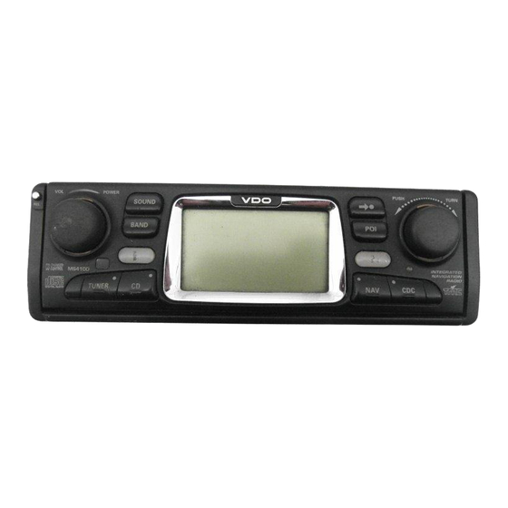
OPERATION Control elements POWER PUSH TURN SOUND BAND TUNER 1 REL ..Release button for removable control panel 2 VOL – POWER . Press: Switching on / off ... . Turn: Set volume 3 TUNER . -
Page 22: Displays
OPERATION Displays In radio mode: : Traffic Announcements / Time TMC (see “INFORMATION” menu) Preset number Waveband Selected search sensitivity Frequency (for automatic search tuning) Selected search mode Program (Station) name (only with RDS stations) In CD player mode: Time A disc is in the player : Random playback CD title (if entered) -
Page 23: Inserting A Cd
OPERATION Inserting a CD 1. Open the front panel. 2. Insert the CD into the drive (printed side up). For audio CDs, playback starts automatically. 3. Close the front panel. Removing a CD 1. Press the eject button to open the front panel. 2. -
Page 24: Menu Operation
OPERATION Menu operation Cursor The currently selected line or field on the screen is designated as the cursor. The cursor is identified by an inverse field (white letters on black background). Move the cursor by turning the PUSH – TURN button. -
Page 25: Entering Letters
OPERATION Entering letters Characters are entered by selecting letters from a list. In the following, this type of entering will simply be called “typewriter”. Move the cursor to the desired letter by turning the PUSH – TURN button. Confirm your selection by pressing the PUSH – TURN button. -
Page 26: Normal And Expert Modes
OPERATION Normal and expert modes With its radio, CD and CD changer modes, the unit offers two possible methods for selecting the functions. You can choose between the “ ” and the “ “ modes. The “ “ mode reduces the number of operator steps when selecting search functions. -
Page 27: Information" Menu
“INFORMATION” MENU The “INFORMATION” menu The “ “ menu allows you to configure the type and amount of information the unit will receive via the radio data system (RDS). Press the button. The “ “ menu is displayed. The following options are available: TMC Scan (Traffic Message Channel) If you activate this function, the automatic search will only look for stations transmitting TMC information. - Page 28 “INFORMATION” MENU Behaviour of TMC and TA You have a choice between the TMC Scan and the traffic announcement (TA) functions. You cannot select both functions simultaneously. If you switch on TMC Scan, you ensure that the radio will only search for stations transmitting TMC data during the automatic search.
-
Page 29: Sound Settings
SOUND SETTINGS The “SOUND” menu In the “ “ menu, you can set your navigation radio’s sound and several other sound reproduction parameters to your own preferences. Press the SOUND button. The “ “ menu is displayed. The following options are available: Sound settings Select the desired option by turning the PUSH –... - Page 30 SOUND SETTINGS Sound Setup Setting one of the following functions: – : Reset the sound setting to the factory-set values and switch off loudness. – Activate this function to equalise volume differences between the various sound sources. – Set the enhancement of low tones at loudness. –...
-
Page 31: Radio
RADIO Radio Listening to radio If the unit is not yet in radio mode: Press the TUNER button. Select waveband In radio mode: Press the BAND button. Select the desired waveband and press the PUSH – TURN button to confirm. Setting stations Stations can be set or sought in various manners (Example user mode “... -
Page 32: The "Radio" Menu
RADIO The “RADIO” menu In radio mode: Press the TUNER button. The “ “ menu is displayed. The following functions are available: RDS Memo (only on FM) Searches for all currently available RDS stations and stores them in alphabetic order. Activate this function to refresh the RDS Memo. - Page 33 RADIO Extra info Display of information on the selected station: – recall number (if the station was stored), – station name (for RDS stations), – frequency, – program type (PTY, if the station transmits the PTY ID) and – the selected sound type for radio mode. AF Retuning (only on FM) Activate this function to achieve the best possible reception of the selected station.
-
Page 34: Cd Player
CD PLAYER CD player You can play 12 cm audio CDs on your CD player. We strongly recommend playing only 12 cm CDs. Please do not use 8 cm CDs (neither with nor without adapter). On no account must unusually-shaped CDs be inserted into the player. If you ignore these recommendations, you risk damaging your unit. -
Page 35: The "Cd" Menu
CD PLAYER The “CD” menu In CD player mode: Press the CD button. The “ “ menu is displayed. The following functions are available: Scan Activate this function to briefly scan all tracks on the inserted CD. Press the PUSH – TURN button in order to cancel the scanning process and to listen to the track of your choice. -
Page 36: Cd Changer
CD CHANGER CD changer A VDO Dayton CD changer CH0400 (4 CDs), CH0600 (6 CDs) or CH1000 (10 CDs) can be connected to the navigation radio. We strongly recommend only playing 12 cm CDs. Please do not use 8 cm CDs (neither with nor without adapter). -
Page 37: The "Cd Changer" Menu
CD CHANGER The “CD CHANGER” menu In CD player mode: Press the CDC button. The “ “ menu is displayed. The following functions are available: Scan Activate this function to briefly scan all tracks on the currently selected CD. Press the PUSH – TURN button in order to cancel the scanning process and to listen to the track of your choice. -
Page 38: Initialisation
INITIALISATION The “INITIALISATION” menu Select “ “ in one of the following menus: “ ,“ “ ,“ “ “ or “ “. The “ “ menu is displayed. The “ “ menu allows you to adjust the navigation radio to your needs. The following functions are available: Telephone Adapt your unit’s telephone input to your car phone:... - Page 39 INITIALISATION Scan Time Setting for the scan time for frequency, storage or track scanning. Choose 5, 10 or 15 seconds. On / Off Logic Activate this function to limit the operation of the device to one hour after the ignition key is removed. Warning light If this function is activated, the red warning light will blink when the operating panel and the ignition key are removed.
-
Page 40: Navigation
NAVIGATION Navigation A VDO Dayton map CD must be inserted into the unit’s CD player in order to be able to use the navigation function of your navigation radio. If the unit is not yet in navigation mode: Press the NAV button. -
Page 41: Destination Input
NAVIGATION Destination input Destinations may be entered in several ways: – Entering city, road and number or crossroads by means of the “typewriter.” See the following page. – Loading an address stored in the personal address book. See page 58. –... - Page 42 NAVIGATION Entering a new address An entry assistant will help you enter a new address. It will lead you step by step through all the necessary entries such as country, city, road, house number or cross- roads and desired routing criterion. 1st Step: Country Select “...
- Page 43 NAVIGATION 4th Step: House number or junction If house numbers are available for a selected road, they can be entered with a separate input menu. If no house numbers are available, the system automatically jumps to the “ “ input menu. If no junction is available, this step will be skipped.
-
Page 44: Special Destinations
NAVIGATION Special destinations You may also input the destination address by selecting special facilities stored in the database. These include e.g.: – airports, – hotels, – petrol station, – car repair garages – car parks, etc. Depending upon the information already entered in the destination input screen, a list of general interest facilities appears which are is present on the current map CD. - Page 45 NAVIGATION Special facilities in the vicinity of the current car position You may also set a destination address by selecting a special facility in the vicinity of the current vehicle location. Press the POI button, select “ “ in the destination input menu. A list of categories of special facilities is shown.
-
Page 46: Viapoint Input
NAVIGATION Viapoint input If you wish to visit other locations on route to the entered destination address, these can be stored as via points. The navigation system then plans the route to include the via points in the given sequence before the destination address is reached. - Page 47 NAVIGATION Delete via points not reached Via point which you have not reached or which are no longer desirable to you must be deleted from the via point list so that the navigation system may plan the route to the next via point or to the final destination.
-
Page 48: Guidance Screen
NAVIGATION Guidance screen The guidance screen appears as soon as you activate the guidance. The guidance screen displays the following information: 1 Guidance information: A graphic display of the next crossroads or junction. In addition, directional changes are announced with audible messages. 2 Road into which to turn at the next announcement. -
Page 49: Audible Messages
NAVIGATION Audible messages As soon as you have activated guidance, the navigation radio will give you audible driving directions - in addition to the symbols in the guidance screens. Commonly, the directive to turn into another road consists of two voice messages: an early warning the instruction to turn Repeating voice message... - Page 50 NAVIGATION On longer route segments without junctions or crossroads, an arrow following the course of the road is displayed. Guidance beyond digitised roads If you leave a digitised road, the arrow pointing to the nearest digitised road will appear automatically. If that is the case, continue in the direction of the arrow until you reach a digitised road.
-
Page 51: Road List Display
NAVIGATION Road list display As soon as a route is planned, this option is available on the guidance screen. Confirm “ “ on the guidance screen. The list of segments of the planned route displays. You can scroll through the list by turning the PUSH – TURN button. Select “... - Page 52 NAVIGATION i3 System info Display of the following information: 1. Route planning criterion selected: C: Fastest – V: Shortest – N: Main roads – M: No main roads – 2. GPS reception status: Displays the number of GPS satellites received. With an unobstructed view of the sky, up to 8 satellites may be displayed.
- Page 53 NAVIGATION i5 Traffic information Information screen i5 is only available if the radio is receiving a station transmitting traffic information and if one or more traffic obstructions are reported on your route. The following information is displayed: – Number and count of available i5 information screens (traffic obstructions);...
-
Page 54: Dynamic Guidance With Tmc
NAVIGATION Dynamic guidance with TMC With RDS TMC (Traffic Message Channel), the current traffic situation is taken into account when planning the route to your destination. You will be informed, for example, of accidents, congestion or construction sites as soon as such a traffic situation occurs. - Page 55 NAVIGATION Bypassing a traffic obstruction When you approach the last exit before reaching a traffic obstruction, the navigation system will alert you and offer you the option of planning a detour route. As soon as a traffic obstruction is detected on your route and the detour option is displayed on the guidance screen: Confirm the detour option in the top line of the guidance screen.
-
Page 56: Alternative Route
NAVIGATION Alternative route During guidance, you can cause the navigation system to plan an alternative route. Use this function if you want to avoid e.g. traffic jams or if you wish to plan an alternative route. The alternative route will be calculated for a selectable distance from the current car position. -
Page 57: Address Manager
NAVIGATION Address manager The navigation radio offers the opportunity of storing at least 30 destination addresses in a personal address book. Select “ “ in the main menu and confirm the selection. The address manager is displayed. The following options are available: Storing addresses in the address book If you have not yet entered a destination address: Enter the data of the desired destination address... - Page 58 NAVIGATION Store car position Would you like to store a favourite restaurant in the destination memory? You can store your current car position as follows: Select “ “ in the address manager. The name input menu appears. Enter a name or cancel the name input with The current vehicle location is stored as an address.
-
Page 59: Emergency Menu
NAVIGATION Emergency menu In the main menu, select “ “. The “ “ menu is displayed. In the “ “ menu, you have the following options: GPS position Display of the current geographic vehicle location as calculated by the Global Position- ing System. -
Page 60: System Settings
NAVIGATION System settings To customise the navigation functions to your own needs, you can change several settings. In the main menu, select “ “. The “ “ menu is displayed. The following information screens are available: Route selection Select the preferred criterion: Fastest C: Fastest route preferred –... - Page 61 CD (included). Select the language to be replaced. You will be prompted to insert the software CD. Insert the VDO Dayton system software CD in the CD player of the radio. Follow the system instructions for loading other languages.
- Page 62 NAVIGATION Measuring units Choose between the following units of measurement for distance: – Metric: Display in kilometres and metres. – Anglo: Display in miles and yards. – American: Display in miles, half and quarter miles and feet. Default settings Select this option in order to reset all user-defined settings to their default values. All entries in the address book will remain stored.
-
Page 63: Map Cds With Travel Guide Information
NAVIGATION Map CDs with travel guide information Map CDs with travel guide information for specific destinations are identified by the I symbol displayed on the screen. If you insert such a map CD, you will receive additional information about many of the stored destinations. For example, when choosing a hotel, you will find information about room prices and you can call up the telephone number for reservations. -
Page 64: Troubleshooting
TROUBLESHOOTING Troubleshooting In rare instances, your navigation radio may not function the way you expect it to. Before calling for service please read the operating instructions and go through the following check list; it may be possible to easily remedy an apparent malfunction. Symptoms Possible cause / remedy General... - Page 65 TMC data. If you cannot find a solution to any problem that may occur, contact an authorised VDO Dayton service agent or call our Customer Helpdesk: 0121 344 5400 1 800 335 282 Toll Free or (03) 94503166...
- Page 66 MO 4130 New functions MO 4130: New guidance screen: Route direction arrow and early warning simultaneously, at a glance. Improved acoustic guidance: Numerical prompt for main roads and road junctions. Advanced TMC: Traffic information on the current location, destination and the planned route with detail display.
- Page 67 MO 4130 Traffic information In the main menu, the traffic information option is now available. Here, the traffic conditions received via RDS-TMC are displayed in three categories: – At the current location, – at the destination, and – on the planned route. As usual during guidance, the navigation system displays the road obstructions on the planned route (on info screen i5).
- Page 68 3111 115 3410.2 11/2001 ri 1471534102...